CN215068579U - Electric power wire alarm device - Google Patents
Electric power wire alarm device Download PDFInfo
- Publication number
- CN215068579U CN215068579U CN202120642049.2U CN202120642049U CN215068579U CN 215068579 U CN215068579 U CN 215068579U CN 202120642049 U CN202120642049 U CN 202120642049U CN 215068579 U CN215068579 U CN 215068579U
- Authority
- CN
- China
- Prior art keywords
- fixedly connected
- worm
- front side
- alarm body
- plate
- Prior art date
- Legal status (The legal status is an assumption and is not a legal conclusion. Google has not performed a legal analysis and makes no representation as to the accuracy of the status listed.)
- Active
Links
Images


Landscapes
- Emergency Alarm Devices (AREA)
Abstract
The utility model discloses an electric power electric wire alarm device, relate to the electric power field, including the alarm body, the rear side of alarm body is provided with the mounting panel, the mounting hole has all been seted up to the front side four corners department of mounting panel, the fixed in-connection of front side of mounting panel has the fixed plate of two symmetric distributions, one side that two fixed plates are relative is connected with the spool through bearing rotation jointly, the outside of spool is provided with the lifting rope, the bottom of lifting rope is provided with the snak link, the rear side fixedly connected with connecting plate of alarm body, the top fixedly connected with of connecting plate and the corresponding solid fixed ring of snak link, the right side fixedly connected with solid fixed cylinder of one of them fixed plate, rotate through the bearing in the solid fixed cylinder and be connected with the worm, the front side meshing of worm is connected with the turbine. The utility model discloses can conveniently carry out the dismouting to the alarm body to be convenient for overhaul the alarm body, and can effectually increase the stability that the alarm body was placed.
Description
Technical Field
The utility model relates to an electric power field, in particular to electric power electric wire alarm device.
Background
The power cable is used for transmitting and distributing electric energy, is commonly used for urban underground power grids, power station leading-out lines, power supply inside industrial and mining enterprises and power transmission lines under river-crossing seawater, and has a gradually increasing proportion in the power line. The power cable is a cable product used for transmitting and distributing high-power electric energy in a main line of a power system, and comprises various voltage grades of 1-500KV and above and various insulated power cables, and the power wire is mostly subjected to safety detection by using an alarm device when in use.
When the alarm device is used, the alarm device is mostly fixed on a wall body, the installation position is higher, when the alarm device needs to be overhauled, the alarm device can be taken down only by manually climbing to the position where the alarm device is installed by means of tools, the operation is inconvenient, and the maintenance difficulty is increased.
Therefore, it is necessary to invent a power line alarm device to solve the above problems.
SUMMERY OF THE UTILITY MODEL
An object of the utility model is to provide an electric power electric wire alarm device to what provide among the above-mentioned background art needs the manual work to climb to the position that alarm device installed with the help of the instrument, just can take off alarm device, and is too inconvenient, has increased the problem of the maintenance degree of difficulty.
In order to achieve the above object, the utility model provides a following technical scheme: the utility model provides an electric power electric wire alarm device, includes the alarm body, the rear side of alarm body is provided with the mounting panel, the mounting hole has all been seted up to the front side four corners department of mounting panel, the fixed in-connection in front side of mounting panel has the fixed plate of two symmetric distributions, two one side that the fixed plate is relative rotates through the bearing jointly and is connected with the spool, the outside of spool is provided with the lifting rope, the bottom of lifting rope is provided with the snak link, the rear side fixedly connected with connecting plate of alarm body, the top fixedly connected with of connecting plate and the corresponding solid fixed ring of snak link, one of them the right side fixedly connected with solid fixed cylinder of fixed plate, rotate through the bearing in the solid fixed cylinder and be connected with the worm, the front side meshing of worm is connected with the turbine, the inner wall of turbine and the outer wall fixed connection of spool.
Preferably, the bottom fixedly connected with hexagonal connector of worm, the bottom of mounting panel is provided with the dwang corresponding with the hexagonal connector.
Preferably, the left and right sides of connecting plate all seted up the recess, and the recess in-connection has reset spring, reset spring keeps away from the one end fixedly connected with gag lever post of recess lateral wall, two the spacing hole corresponding with the gag lever post is all seted up to the relative one side of fixed plate, reset spring's one end is kept away from to the gag lever post sets up to the arc.
Preferably, the front side of the mounting plate is fixedly connected with a supporting plate, the bottom of the supporting plate is fixedly connected with a pushing spring, and the rear side of the connecting plate is fixedly connected with an extrusion plate corresponding to the pushing spring.
Preferably, the rear side fixedly connected with sliding block of stripper plate, the front side of mounting panel is opened and is equipped with the sliding tray corresponding with the sliding block.
Preferably, the outer walls of the worm wheel and the worm are jointly provided with a protective cover, and the protective cover is fixedly connected with the front side of the mounting plate.
The utility model discloses a technological effect and advantage:
1. be provided with the mounting panel through the rear side at the alarm body, connect the mounting panel through using the bolt earlier, and detain the snak link on solid fixed ring, rotate the dwang, the dwang drives the worm and rotates, the worm drives the turbine through the relation of meshing and rotates, the turbine drives the spool and rotates, the spool tightens up the lifting rope, the lifting rope passes through the snak link pulling connecting plate, connecting plate pulling alarm body, thereby upwards promote the alarm body, fix the alarm body, otherwise can dismantle the alarm body, can conveniently carry out the dismouting to the alarm body, thereby be convenient for overhaul the alarm body.
2. Set up flutedly through the lateral wall at the connecting plate to be provided with reset spring in the recess, when the alarm body upwards removed, the lateral wall of gag lever post extrusion fixed plate, and be provided with the arc because of the lateral wall of gag lever post, therefore accessible frictional force extrudees the gag lever post, makes the gag lever post stretch into in the recess on the connecting plate, when the gag lever post corresponds with spacing hole, reset spring promotes the gag lever post and stretches into spacing downthehole, stability that can effectual increase alarm body was placed.
3. The supporting plate is arranged on the front side of the mounting plate, the pushing spring is arranged at the bottom of the supporting plate, when the alarm body needs to be taken down, the pushing spring pushes the extrusion plate, the extrusion plate pulls the connecting plate, the connecting plate pulls the alarm body, the alarm body can be kept away from the mounting plate, and therefore the alarm body can be rapidly detached.
Drawings
Fig. 1 is a schematic view of the overall structure of the present invention;
fig. 2 is a schematic rear side view of the present invention shown in fig. 1;
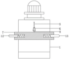
fig. 3 is a schematic structural view of the cross-sectional view taken along the direction a-a of fig. 1 according to the present invention.
In the figure: 1. an alarm body; 2. mounting a plate; 3. a fixing plate; 4. a reel; 5. a lifting rope; 6. a spring buckle; 7. a connecting plate; 8. a fixing ring; 9. a fixed cylinder; 10. a worm; 11. a turbine; 12. a return spring; 13. a limiting rod; 14. a support plate; 15. a push spring; 16. a pressing plate; 17. a protective cover; 18. rotating the rod.
Detailed Description
The technical solutions in the embodiments of the present invention will be described clearly and completely with reference to the accompanying drawings in the embodiments of the present invention, and it is obvious that the described embodiments are only some embodiments of the present invention, not all embodiments. Based on the embodiments in the present invention, all other embodiments obtained by a person skilled in the art without creative work belong to the protection scope of the present invention.
The utility model provides a power wire alarm device as shown in figures 1-3, which comprises an alarm body 1, a mounting plate 2 is arranged at the rear side of the alarm body 1, mounting holes are arranged at the four corners of the front side of the mounting plate 2, two symmetrically distributed fixing plates 3 are fixedly connected in the front side of the mounting plate 2, one opposite sides of the two fixing plates 3 are connected with a scroll 4 through a bearing, a lifting rope 5 is arranged at the outer side of the scroll 4, a spring buckle 6 is arranged at the bottom of the lifting rope 5, a connecting plate 7 is fixedly connected at the rear side of the alarm body 1, a fixing ring 8 corresponding to the spring buckle 6 is fixedly connected at the top of the connecting plate 7, the right side of one of the fixed plates 3 is fixedly connected with a fixed cylinder 9, a worm 10 is rotatably connected in the fixed cylinder 9 through a bearing, the front side of the worm 10 is meshed and connected with a worm wheel 11, and the inner wall of the worm wheel 11 is fixedly connected with the outer wall of the scroll 4.
Meanwhile, the hexagonal connector is fixedly connected to the bottom of the worm 10, the rotating rod 18 corresponding to the hexagonal connector is arranged at the bottom of the mounting plate 2, the rotating rod 18 can be taken down when the worm is not used, and when the worm is needed to be used, the worm 10 can be rotated only by inserting the rotating rod 18 into the hexagonal connector.
In addition, the left and right sides of connecting plate 7 all has seted up the recess, and the recess in-connection has reset spring 12, and reset spring 12 keeps away from the one end fixedly connected with gag lever post 13 of recess lateral wall, and the spacing hole corresponding with gag lever post 13 has all been seted up to two relative one sides of fixed plate 3, and reset spring 12 was kept away from to gag lever post 13 one end sets up to the arc, stability that can effectual increase alarm body 1 placed.
Then, the front side fixedly connected with backup pad 14 of mounting panel 2, the bottom fixedly connected with of backup pad 14 promotes spring 15, the rear side fixedly connected with of connecting plate 7 with promote spring 15 corresponding stripper plate 16, when needing to take off alarm body 1, promote spring 15 and promote stripper plate 16, stripper plate 16 pulling connecting plate 7, connecting plate 7 pulling alarm body 1 can make alarm body 1 keep away from mounting panel 2 to dismantle alarm body 1 fast.
More specifically, the rear side fixedly connected with sliding block of stripper plate 16, the front side of mounting panel 2 is opened and is equipped with the sliding tray corresponding with the sliding block, and 16 pulling sliding blocks of stripper plate make the sliding tray of sliding block on mounting panel 2 in slide, can effectually lead to connecting plate 7.
It should be further noted that the outer walls of the worm wheel 11 and the worm 10 are provided with the protective cover 17, and the protective cover 17 is fixedly connected with the front side of the mounting plate 2, so that the worm wheel 11 and the worm 10 can be protected conveniently, and the problem that the worm wheel 11 and the worm 10 cannot rotate due to rusting is avoided.
The utility model discloses the theory of operation:
disassembling and assembling: connect mounting panel 2 through using the bolt earlier, and detain snak link 6 on solid fixed ring 8, rotate dwang 18, dwang 18 drives worm 10 and rotates, worm 10 drives turbine 11 through the relation of meshing and rotates, turbine 11 drives spool 4 and rotates, 4 tightens up lifting rope 5 of spool, lifting rope 5 passes through snak link 6 pulling connecting plate 7, connecting plate 7 pulling alarm body 1, thereby upwards promote alarm body 1, fix alarm body 1, otherwise can dismantle alarm body 1, can conveniently carry out the dismouting to alarm body 1, thereby be convenient for overhaul alarm body 1.
And (3) stabilizing: when alarm body 1 upwards moved, gag lever post 13 extruded the lateral wall of fixed plate 3, and be provided with the arc because of the lateral wall of gag lever post 13, consequently accessible frictional force extrudes gag lever post 13, makes gag lever post 13 stretch into the recess on connecting plate 7 in, when gag lever post 13 corresponds with spacing hole, reset spring 12 promoted gag lever post 13 and stretches into spacing downthehole, stability that can effectual increase alarm body 1 placed.
Finally, it should be noted that: although the present invention has been described in detail with reference to the foregoing embodiments, it will be apparent to those skilled in the art that modifications and variations can be made in the embodiments or in part of the technical features of the embodiments without departing from the spirit and the scope of the invention.
Claims (6)
1. The utility model provides a power line alarm device, includes alarm body (1), its characterized in that: the rear side of the alarm body (1) is provided with a mounting plate (2), the four corners of the front side of the mounting plate (2) are provided with mounting holes, the front side of the mounting plate (2) is fixedly connected with two symmetrically distributed fixing plates (3), one opposite side of the two fixing plates (3) is connected with a reel (4) through a bearing in a rotating manner, the outer side of the reel (4) is provided with a lifting rope (5), the bottom of the lifting rope (5) is provided with a spring buckle (6), the rear side of the alarm body (1) is fixedly connected with a connecting plate (7), the top of the connecting plate (7) is fixedly connected with a fixing ring (8) corresponding to the spring buckle (6), one of the fixing plates (3) is fixedly connected with a fixing cylinder (9) on the right side, and a worm (10) is rotatably connected in the fixing cylinder (9) through a bearing, the front side of the worm (10) is connected with a worm wheel (11) in a meshed mode, and the inner wall of the worm wheel (11) is fixedly connected with the outer wall of the reel (4).
2. A power line alarm device according to claim 1, wherein: the bottom fixedly connected with hexagonal connector of worm (10), the bottom of mounting panel (2) is provided with dwang (18) corresponding with the hexagonal connector.
3. A power line alarm device according to claim 1, wherein: the left and right sides of connecting plate (7) all seted up flutedly, and recess in-connection has reset spring (12), the one end fixedly connected with gag lever post (13), two of recess lateral wall are kept away from in reset spring (12) the spacing hole corresponding with gag lever post (13) is all seted up to one side that fixed plate (3) are relative, reset spring (12) was kept away from in gag lever post (13) one end sets up to the arc.
4. A power line alarm device according to claim 1, wherein: the front side fixedly connected with backup pad (14) of mounting panel (2), the bottom fixedly connected with of backup pad (14) promotes spring (15), the rear side fixedly connected with of connecting plate (7) pushes away the corresponding stripper plate (16) of spring (15).
5. A power line warning device in accordance with claim 4, wherein: the rear side fixedly connected with sliding block of stripper plate (16), the front side of mounting panel (2) is opened and is equipped with the sliding tray corresponding with the sliding block.
6. A power line alarm device according to claim 1, wherein: the outer wall of turbine (11) and worm (10) is provided with protection casing (17) jointly, protection casing (17) and the front side fixed connection of mounting panel (2).
Priority Applications (1)
| Application Number | Priority Date | Filing Date | Title |
|---|---|---|---|
| CN202120642049.2U CN215068579U (en) | 2021-03-30 | 2021-03-30 | Electric power wire alarm device |
Applications Claiming Priority (1)
| Application Number | Priority Date | Filing Date | Title |
|---|---|---|---|
| CN202120642049.2U CN215068579U (en) | 2021-03-30 | 2021-03-30 | Electric power wire alarm device |
Publications (1)
| Publication Number | Publication Date |
|---|---|
| CN215068579U true CN215068579U (en) | 2021-12-07 |
Family
ID=79153271
Family Applications (1)
| Application Number | Title | Priority Date | Filing Date |
|---|---|---|---|
| CN202120642049.2U Active CN215068579U (en) | 2021-03-30 | 2021-03-30 | Electric power wire alarm device |
Country Status (1)
| Country | Link |
|---|---|
| CN (1) | CN215068579U (en) |
-
2021
- 2021-03-30 CN CN202120642049.2U patent/CN215068579U/en active Active
Similar Documents
| Publication | Publication Date | Title |
|---|---|---|
| CN211003887U (en) | Adjustable power cable pay-off device | |
| CN215068579U (en) | Electric power wire alarm device | |
| CN103489281B (en) | Alarm is torn in ground wire leakproof open | |
| CN216811194U (en) | Electric power steel pipe tower convenient to climbing work | |
| CN202892704U (en) | Electric transmission line tower climbing falling-proof device | |
| CN212412738U (en) | Relay protection device and functional plug-in thereof | |
| CN211716200U (en) | Self-generating high-altitude monitoring device | |
| CN210599703U (en) | Fixing clamp for electric power engineering | |
| CN112875438A (en) | Special cable winch for emergency rescue vehicle | |
| CN108598826B (en) | Auxiliary tool for assembling and disassembling 10kV line grounding wire | |
| CN210779884U (en) | Make things convenient for cable testing bridge of dismouting | |
| CN216959218U (en) | Efficient cable protection device for electrical engineering | |
| CN221100870U (en) | Electric energy meter with alarm function | |
| CN217235196U (en) | Fire protection and security alarm equipment of instrument installation of being convenient for exempts from | |
| CN216198078U (en) | Cable traction tension overload protection device for coal mining machine in coal mine | |
| CN209929876U (en) | Lead clamping and fixing device for cable installation | |
| CN113053046A (en) | Outer broken intelligent early warning device is prevented to circuit based on cable marks stake | |
| CN217182650U (en) | Protection device for be used for direct current power supply system of transformer substation | |
| CN217325117U (en) | Traffic warning lamp device for road traffic and transportation engineering | |
| CN219203047U (en) | Rain-proof cover of relay | |
| CN211321424U (en) | Wired multi-channel color night vision card machine | |
| CN215450347U (en) | Outdoor terminal waterproof device of perimeter security system | |
| CN216720837U (en) | Portable power line support for electric power engineering | |
| CN210196398U (en) | Novel device for mounting speed reducer | |
| CN217816074U (en) | Production safety early warning monitoring device suitable for workshop |
Legal Events
| Date | Code | Title | Description |
|---|---|---|---|
| GR01 | Patent grant | ||
| GR01 | Patent grant |