CN215064276U - Wind power generation coaxiality detection device - Google Patents
Wind power generation coaxiality detection device Download PDFInfo
- Publication number
- CN215064276U CN215064276U CN202120805531.3U CN202120805531U CN215064276U CN 215064276 U CN215064276 U CN 215064276U CN 202120805531 U CN202120805531 U CN 202120805531U CN 215064276 U CN215064276 U CN 215064276U
- Authority
- CN
- China
- Prior art keywords
- main shaft
- magnetometer
- ball screw
- support
- linear guide
- Prior art date
- Legal status (The legal status is an assumption and is not a legal conclusion. Google has not performed a legal analysis and makes no representation as to the accuracy of the status listed.)
- Active
Links
Images


Landscapes
- A Measuring Device Byusing Mechanical Method (AREA)
Abstract
The utility model relates to a device for detecting the coaxiality of a main shaft of a wind driven generator, which comprises a detection platform arranged on the ground, a V-shaped block fixedly connected with the upper surface of the detection platform, a magnetometer bracket assembly arranged on the detection platform and far away from one side of the V-shaped block, a magnetometer seat arranged on the magnetometer bracket assembly, a magnetometer arranged on the magnetometer seat and a clamp arranged at one end of the main shaft of the tested generator; the bracket assembly of the magnetometer comprises a support column, a linear guide rail pair, a support, a magnetometer fixing plate and a ball screw pair. The beneficial effects of the utility model are that through the vice magnetic meter on ball screw and the linear guide that sets up are vice, can carry out the axiality to the generator main shaft and detect, avoided the handheld error that detects of measurement personnel, improved detection efficiency and degree of accuracy.
Description
Technical Field
The utility model relates to a detection device field, in particular to aerogenerator main shaft axiality detection device.
Background
The detection device is a general name of equipment for detecting all parts of the wind driven generator, and at present, in order to prevent a main shaft of the wind driven generator from deforming in the transportation and carrying processes, the main shaft of the wind driven generator needs to be rechecked before being installed; the coaxiality of the main shaft of the generator must be ensured, if the coaxiality deviation is overlarge, the abrasion of each moving part is accelerated if the moving part is light, and the generator support is damaged if the moving part is heavy.
However, the existing coaxiality detection is basically that detection personnel hold a detection instrument to detect, so that not only is the working efficiency reduced, but also human errors exist; the coaxiality detection of the main shaft of the general wind driven generator needs to be carried back to a maintenance workshop for detection, and is long in distance, low in efficiency and quite inconvenient.
Therefore, how to design a quick device for detecting the coaxiality of the main shaft of the wind driven generator on site becomes a problem to be solved at present.
SUMMERY OF THE UTILITY MODEL
The to-be-solved technical problem of the utility model is to provide an aerogenerator main shaft axiality detection device, the axiality of detection generator main shaft that can convenient and fast.
In order to solve the above problems, the utility model adopts the following technical proposal.
The utility model provides a aerogenerator main shaft axiality detection device for the detection of generator main shaft axiality, including set up subaerial testing platform, with testing platform upper surface fixed connection's V-arrangement piece, set up on the testing platform and keep away from the megmeter support assembly of V-arrangement piece one side, set up and be in magnetic gauge stand on the megmeter support assembly and set up the megmeter on the megmeter support stand.
Furthermore, the magnetometer bracket assembly comprises a support column, a linear guide rail pair, a support, a magnetometer fixing plate and a ball screw pair; the two support columns are respectively arranged at two ends of the detection platform; the linear guide rail pair comprises an optical axis and a sliding block which can slide on the optical axis; the number of the linear guide rail pairs is two, and the number of the supports is four; the optical axis of each set of linear guide rail pair is fixedly connected with the support column through two supports; the magnetic meter fixing plate is fixedly connected with the sliding block; the ball screw pair comprises a ball screw, a ball screw nut and a screw support; the screw rod support is arranged on the back of one side of the support column, which is provided with the linear guide rail pair; the ball screw is fixedly connected with the screw support, and the ball screw nut is in threaded transmission with the ball screw; the ball screw is fixedly connected with the fixed plate of the magnetic meter.
Further, the device also comprises a motor for driving the ball screw pair; the motor is fixedly connected with the lead screw support, and an output shaft of the motor is fixedly connected with the ball screw.
Further, the device also comprises a generator main shaft arranged on the V-shaped block and a clamp arranged at one end of the generator main shaft.
Further, the clip comprises a clamping arm and a spring; the clamping arm is provided with an object clamping end and a handle end; the object clamping end is fixedly connected with a main shaft of the generator; the clamping arms are two, the middle parts of the two clamping arms are hinged together, and the spring is arranged between the two handle ends.
Further, the spring is a tension spring.
Furthermore, a rubber plate is arranged on the contact surface of the clamping arm and the main shaft of the generator
Furthermore, the axis of the main shaft of the generator is parallel to the axis of the linear guide rail pair, and the axis of the linear guide rail pair is parallel to the axis of the ball screw pair.
The utility model has the advantages that:
1. the main shaft of the wind driven generator can be clamped through the arranged clamp, and the main shaft of the wind driven generator is rotated when the coaxiality of the main shaft of the wind driven generator is detected, so that time and labor are avoided when the main shaft of the wind driven generator is directly rotated manually; due to the fact that the extension spring is arranged on the clamp, the clamp can be fixed on the main shaft of the engine under the action of elastic force as long as the clamp is opened to clamp the main shaft of the generator, and complexity of repeatedly opening the clamp is avoided;
2. the magnetic meter can move along the axis direction of the main shaft of the generator through the two linear guide rail pairs, and the coaxiality of the main shaft of the generator is detected;
3. through the arranged ball screw pair and the motor, the sliding block of the linear guide rail can be driven to do linear motion, the sliding block moves to enable the sliding block and the fixed magnetic meter fixing plate fixed by the sliding block to move together, and then the magnetic meter can do linear motion, so that the main shaft of the generator can be conveniently detected; the ball screw pair adopted by the utility model has small driving torque which is only 1/3 of the sliding screw rod; the precision is high, and micro-feeding can be realized; no gap, high rigidity and the like;
4. the rubber plate arranged on the clamping arm prevents the clamp from abrading the surface of the main shaft of the generator when the main shaft of the generator is clamped;
5. through the combination of the arranged magnetic gauge stand and the dial indicator, the coaxiality of the main shaft of the generator can be measured by rotating the main shaft of the generator to be measured;
6. the device has simple structure and convenient operation, can quickly detect the coaxiality of the main shaft of the generator, and is a detection device worthy of popularization.
Drawings
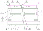
Fig. 1 is a schematic front view of the structure of embodiment 1 of the present invention;
fig. 2 is a right side view of the structure of embodiment 1 of the present invention;
fig. 3 is a schematic plan view of the structure of embodiment 1 of the present invention;
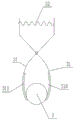
fig. 4 is a schematic view of a clip structure according to embodiment 1 of the present invention;
fig. 5 is a schematic view of a clip structure according to embodiment 2 of the present invention.
The reference numbers in the figures illustrate:
the device comprises a detection platform 1, a 2-V-shaped block, a 3-generator spindle, a 4-support column, a 5-support, a 6-linear guide rail pair, a 7-motor, an 8-ball screw pair, a 9-dial indicator, a 10-magnetic gauge seat, an 11-magnetic gauge fixing plate, a 12-screw support, a 30-clamp, a 31-clamping arm, a 32-spring and a 310-rubber plate.
Detailed Description
The drawings in the embodiments of the present invention will be combined; the technical scheme in the embodiment of the utility model is clearly and completely described; obviously; the described embodiments are only some of the embodiments of the present invention; but not all embodiments, are based on the embodiments of the invention; all other embodiments obtained by a person skilled in the art without making any inventive step; all belong to the protection scope of the utility model.
In the description of the present invention, it should be noted that the terms "upper", "lower", "inner", "outer", "top/bottom", left and right. The positional or orientational relationships indicated before, after, etc. are based on the positional or orientational relationships shown in the drawings and are merely for convenience of description and simplicity of description, and are not intended to indicate or imply that the device or element so referred to must have a particular orientation, be constructed and operated in a particular orientation, and therefore should not be construed as limiting the invention. Furthermore, the terms "first," "second," "one end," and "the other end" are used for descriptive purposes only and are not to be construed as indicating or implying relative importance. In the description of the present invention, it should be noted that, unless explicitly stated or limited otherwise, the terms "disposed", "sleeved/connected", "connected", and the like are to be understood in a broad sense, such as "connected", which may be fixedly connected, detachably connected, or integrally connected; can be mechanically or electrically connected; they may be connected directly or indirectly through intervening media, or they may be interconnected between two elements. The specific meaning of the above terms in the present invention can be understood in specific cases to those skilled in the art.
Example 1
As shown in fig. 1-4:
the utility model provides a aerogenerator main shaft axiality detection device for detect the axiality of generator main shaft 3, including set up subaerial testing platform 1, with V-arrangement piece 2 that fixed surface is connected on testing platform 1, set up and be in testing platform 1 is last and keep away from the meglumine support assembly of V-arrangement piece 2 one side, set up and be in magnetic gauge stand 10 on the meglumine support assembly and set up the meglumine 9 on the meglumine support assembly 10.
The magnetometer stand assembly comprises a support column 4, a linear guide rail pair 6, a support 5, a magnetometer fixing plate 11 and a ball screw pair 8; the two support columns 4 are respectively arranged at two ends of the detection platform 1 far away from the V-shaped block 2; the linear guide rail pair 6 comprises an optical axis and a slide block which can slide on the optical axis; the number of the linear guide rail pairs 6 is two, and the number of the supports 5 is four; the optical axis of each linear guide rail pair 6 is fixedly connected with the support column 4 through two supports 5; the magnetic force meter fixing plate 11 is fixedly connected with the sliding block; the ball screw pair 8 comprises a ball screw, a ball screw nut and a screw support 12; the screw rod support 12 is arranged on the back of one side of the support column 4 provided with the linear guide rail pair 6; the ball screw is fixedly connected with the screw support 12, and the ball screw nut is in threaded transmission with the ball screw; the ball screw is fixedly connected with the fixed plate 11 of the magnetometer. The axis of the generator main shaft 3 is parallel to the axis of the linear guide rail pair 6, and the axis of the linear guide rail pair 6 is parallel to the axis of the ball screw pair 8.
The device also comprises a motor 7 for driving the ball screw pair 8; the motor 7 is fixedly connected with the lead screw support 12, and an output shaft of the motor 7 is fixedly connected with the ball screw.
The generator further comprises a generator main shaft 3 arranged on the V-shaped block 4 and a clamp 30 arranged at one end of the generator main shaft 3.
The clip comprises a gripping arm 31 and a spring 32; the clamping arm 31 is provided with an object clamping end and a handle end; the object clamping end is fixedly connected with a main shaft 3 of the generator; the number of the clamping arms 31 is two, the middle parts of the two clamping arms 31 are hinged together, and the spring 32 is arranged between the two handle ends.
The spring 32 is a compression spring.
The utility model discloses a ball is vice 8 adopts the inner loop ball, and the ball keeps in contact with the lead screw all the time at the circulation in-process. The balls are each circulated in a closed circuit called a row, and the number of strokes contained in each circulated closed circuit is called the number of turns. Every nut of the internal circulation ball screw pair has 2 rows, 3 rows, 4 rows, 5 rows and so on, every row has only the round, the utility model discloses a four rows have following advantage:
1. the internal circulation design saves the use space;
2. 1/3 with small driving torque and only a sliding screw rod;
3. the precision is high, and micro-feeding can be realized;
4. no gap and high rigidity.
The working process of the device is as follows:
fixing the V-shaped block 2 on the detection platform 1 according to the length of the generator main shaft 3, and adjusting a connecting rod of the magnetic gauge stand 10 according to the position of the generator main shaft 3, so that a probe of the dial indicator 9 is pressed on the surface of the generator main shaft 3, and the pointer of the dial indicator 3 is required to be pressed for not less than two circles and not more than three circles; fixing the clamp 30 at one end of the generator main shaft 3, slowly rotating the generator main shaft 3 by using the clamp 30, measuring the data of the generator main shaft at intervals of 45 degrees, and comparing the measured data with a standard to judge whether the measured data is qualified.
After the first position data is measured, adjusting a magnetic meter base 10 to enable a probe of a dial indicator 9 to be separated from a generator spindle 3, starting a motor 7, driving a ball screw to rotate by the motor 7, driving the ball screw to slide along a linear guide rail pair, driving a magnetic meter fixing plate 11 fixed with the ball screw to move to a specific position needing coaxiality detection along the linear guide rail pair 6, and carrying out coaxiality detection; the procedure is the same as before. After the detection is finished, the equipment can be moved to the next area needing to be detected, and the detection is continued until the generator main shaft 3 is detected according to a set detection program; the detected data is compared with the standard data to judge whether the data is qualified or not.
Example 2
As shown in figure 5 of the drawings,
the present embodiment has the same structure as embodiment 1, except that a rubber plate 310 is provided on the contact surface of the clamping arm 31 and the generator main shaft 3. Through the rubber plate 310 arranged on the clamping arm 31, the clamp 3 is prevented from wearing the surface of the generator main shaft 3 when clamping the generator main shaft 3, and the generator main shaft 3 is prevented from being damaged.
The working principle of this embodiment is the same as that of embodiment 1, and the description will not be repeated.
The above; is only a preferred embodiment of the present invention; however, the scope of protection of the present invention is not limited thereto; any person skilled in the art is within the technical scope of the present disclosure; according to the technical scheme of the utility model and the improvement conception, equivalent substitution or change is carried out; are all covered by the protection scope of the utility model.
Claims (7)
1. The utility model provides a aerogenerator main shaft axiality detection device for the detection of generator main shaft (3) axiality, its characterized in that: the device comprises a detection platform (1) arranged on the ground, a V-shaped block (2) fixedly connected with the upper surface of the detection platform (1), a magnetometer bracket assembly arranged on the detection platform (1) and far away from one side of the V-shaped block (2), a magnetometer seat (10) arranged on the magnetometer bracket assembly and a magnetometer (9) arranged on the magnetometer seat (10).
2. The wind driven generator main shaft coaxiality detection device according to claim 1, wherein: the magnetometer stand assembly comprises a support pillar (4), a linear guide rail pair (6), a support (5), a magnetometer fixing plate (11) and a ball screw pair (8); the two support columns (4) are respectively arranged at two ends of the detection platform (1); the linear guide rail pair (6) comprises an optical axis and a sliding block sliding on the optical axis; the number of the linear guide rail pairs (6) is two, and the number of the supports (5) is four; the optical axis of each set of linear guide rail pair (6) is respectively fixedly connected with the support column (4) through a support (5); the magnetic meter fixing plate (11) is fixedly connected with the sliding block; the ball screw pair (8) comprises a ball screw, a ball screw nut and a screw support (12); the screw rod support (12) is arranged on the back of one side of the support column (4) provided with the linear guide rail pair (6); the ball screw is rotationally connected with the screw support (12), and the ball screw nut is in threaded transmission with the ball screw; the ball screw is fixedly connected with a fixed plate (11) of the magnetic meter.
3. The wind driven generator main shaft coaxiality detection device according to claim 2, wherein: the device also comprises a motor (7) for driving the ball screw pair (8); the shell of the motor (7) is fixedly connected with the lead screw support (12), and the output shaft of the motor (7) is fixedly connected with the ball screw.
4. The wind driven generator main shaft coaxiality detection device according to claim 1, wherein: the power generator further comprises a clamp (30) arranged at one end of the generator main shaft (3); the generator main shaft (3) is arranged in a V-shaped groove of the V-shaped block (2).
5. The wind driven generator main shaft coaxiality detection device according to claim 4, wherein: the clip (30) comprises a clip arm (31) and a spring (32); the number of the clamping arms (31) is two, and the middle parts of the two clamping arms (31) are hinged together; the clamping arm (31) is provided with an object clamping end and a handle end; the object clamping end is clamped with the main shaft (3) of the generator; the spring (32) is disposed between the two handle ends.
6. The wind driven generator main shaft coaxiality detection device according to claim 5, wherein: the spring (32) is a pressure spring.
7. The wind driven generator main shaft coaxiality detection device according to claim 5, wherein: and a rubber plate (310) is arranged on the contact surface of the clamping arm (31) and the generator main shaft (3).
Priority Applications (1)
| Application Number | Priority Date | Filing Date | Title |
|---|---|---|---|
| CN202120805531.3U CN215064276U (en) | 2021-04-20 | 2021-04-20 | Wind power generation coaxiality detection device |
Applications Claiming Priority (1)
| Application Number | Priority Date | Filing Date | Title |
|---|---|---|---|
| CN202120805531.3U CN215064276U (en) | 2021-04-20 | 2021-04-20 | Wind power generation coaxiality detection device |
Publications (1)
| Publication Number | Publication Date |
|---|---|
| CN215064276U true CN215064276U (en) | 2021-12-07 |
Family
ID=79106650
Family Applications (1)
| Application Number | Title | Priority Date | Filing Date |
|---|---|---|---|
| CN202120805531.3U Active CN215064276U (en) | 2021-04-20 | 2021-04-20 | Wind power generation coaxiality detection device |
Country Status (1)
| Country | Link |
|---|---|
| CN (1) | CN215064276U (en) |
-
2021
- 2021-04-20 CN CN202120805531.3U patent/CN215064276U/en active Active
Similar Documents
| Publication | Publication Date | Title |
|---|---|---|
| CN216815820U (en) | Ball screw pair friction moment measuring equipment | |
| CN208936962U (en) | A kind of shafting running accuracy optical measuring device | |
| CN215064276U (en) | Wind power generation coaxiality detection device | |
| CN212432020U (en) | Round steel straightness detection device that hangs down | |
| CN211012776U (en) | Intelligent quality monitoring device for bearing ring | |
| CN210051257U (en) | Spring detection equipment capable of testing height | |
| CN215677943U (en) | Rockwell hardness tester based on indentation depth | |
| CN113218288A (en) | Wind power generation coaxiality detection device | |
| CN116520000A (en) | Resistance imitating battery appearance and testing jig thereof | |
| CN208476187U (en) | A kind of measuring tool for heterotypic spring linear measure longimetry | |
| CN214373212U (en) | Machining part elasticity testing arrangement | |
| CN212585607U (en) | Combined type thread gauge convenient for detecting depth | |
| CN214149389U (en) | Intelligent grating type indicator verification instrument | |
| CN214039837U (en) | Large-scale turbonator stator and rotor air gap direct-reading type measuring instrument | |
| CN211147902U (en) | Brush pressure testing device | |
| CN211084984U (en) | Dial indicator calibrating device | |
| CN210374855U (en) | Automatic thread measuring device | |
| CN210487689U (en) | Indoor test piece wave speed test fixing device | |
| CN207675104U (en) | A kind of piece test deflection instrument | |
| CN219914328U (en) | Tool equipment for measuring eccentric shaft size with high precision | |
| CN216745867U (en) | Inner gear ring M value measuring device | |
| CN216745865U (en) | Equipment for measuring bearing clearance | |
| CN219572929U (en) | Step axle axiality detects machine | |
| CN214121126U (en) | Detection tool for detecting diameter and roundness of spherical surface | |
| CN220367274U (en) | Pipeline nondestructive testing machine |
Legal Events
| Date | Code | Title | Description |
|---|---|---|---|
| GR01 | Patent grant | ||
| GR01 | Patent grant |