CN215047656U - Tow tension buffering device for chemical fiber production - Google Patents
Tow tension buffering device for chemical fiber production Download PDFInfo
- Publication number
- CN215047656U CN215047656U CN202121500597.8U CN202121500597U CN215047656U CN 215047656 U CN215047656 U CN 215047656U CN 202121500597 U CN202121500597 U CN 202121500597U CN 215047656 U CN215047656 U CN 215047656U
- Authority
- CN
- China
- Prior art keywords
- fixedly connected
- dwang
- chemical fiber
- fiber production
- relative
- Prior art date
- Legal status (The legal status is an assumption and is not a legal conclusion. Google has not performed a legal analysis and makes no representation as to the accuracy of the status listed.)
- Active
Links
Images


Abstract
The utility model discloses a silk bundle tension buffer for chemical fiber production, including two first dwangs, two the first metal sheet of fixedly connected with is distinguished to one side that first dwang is relative, two the common fixedly connected with second dwang in one side that first metal sheet is relative, two the outer wall left and right sides of second dwang sliding connection respectively has spacing pipe, two the upper and lower both sides of spacing pipe are threaded connection respectively and are fixed establishment, two one side that spacing pipe is relative is fixedly connected with limiting plate, two the upper and lower both sides difference fixedly connected with bleeder mechanism of one side that first metal sheet is relative, fixed establishment includes the threaded rod. The utility model discloses a be provided with rotating tube and antiskid ribbed tile and limiting plate, can twine the silk bundle well to through being provided with first dwang and second dwang, can cushion well through first dwang and second dwang and drag the tension of silk bundle, thereby made things convenient for staff's use.
Description
Technical Field
The utility model relates to a chemical fiber technical field especially relates to a chemical fiber production is with silk bundle tension buffer.
Background
Chemical fibers are generally known as chemical fibers, and are fibers made of natural or synthetic high molecular substances, and are classified into artificial fibers made of natural high molecular substances and synthetic fibers made of synthetic high molecular substances according to the source of the raw materials.
Tow refers to a substantially untwisted long chemical fiber bundle formed by gathering a large number of continuous filaments to be cut into short fibers or made into chemical fiber strands by a drawing method, and a considerable number of single filaments are gathered into a tow after the chemical fiber is spun.
However, in the prior art, the tow tension buffering device for chemical fiber production mostly adopts the rotating rod to directly pull the tows in actual use, so that the tows are easily damaged due to the direct pulling of the tows, the use of workers is not facilitated, and the expected design effect cannot be achieved.
SUMMERY OF THE UTILITY MODEL
An object of the utility model is to provide a chemical fibre production is with silk bundle tension buffer to solve the problem that proposes in the above-mentioned background art.
In order to achieve the above purpose, the utility model adopts the following technical scheme:
the utility model provides a tow tension buffer for chemical fiber production, includes two first dwangs, two the first metal sheet of fixedly connected with respectively is in the relative one side of first dwang, two the common fixedly connected with second dwang in the relative one side of first metal sheet, two sliding connection respectively has spacing pipe, two in the outer wall left and right sides of second dwang the upper and lower both sides of spacing pipe respectively threaded connection have fixed establishment, two respectively fixedly connected with limiting plate, two in the relative one side of spacing pipe the upper and lower both sides difference fixedly connected with bleeder mechanism of the relative one side of first metal sheet.
As a further improvement scheme of the technical scheme: the fixing mechanism comprises a threaded rod, the threaded rod is in threaded connection with the limiting pipe, the other end of the threaded rod is fixedly connected with a knob, and anti-skid lines are carved on the outer wall of the knob.
As a further improvement scheme of the technical scheme: the pressure dividing mechanism comprises a telescopic rod, one side of the telescopic rod is fixedly connected with the side wall of the first metal plate, the other end of the telescopic rod is fixedly connected with a sliding plate, and the other end of the sliding plate is slidably connected with the side wall of the corresponding limiting plate.
As a further improvement scheme of the technical scheme: the outer wall of the telescopic rod is wound with a buffer spring, one side of the buffer spring is fixedly connected with the side wall of the corresponding sliding plate, and the other end of the buffer spring is fixedly connected with the side wall of the adjacent first metal plate.
As a further improvement scheme of the technical scheme: the two opposite sides of the limiting plates are connected with a rotating pipe in a sliding mode, and the two opposite sides of the limiting plates are fixedly connected with anti-skidding plates respectively.
As a further improvement scheme of the technical scheme: the upper side and the lower side of one back side of the two first metal plates are respectively and fixedly connected with a first stabilizer bar, the outer walls of the first stabilizer bars are fixedly connected with a plurality of second stabilizer bars, and the other sides of the second stabilizer bars are respectively and fixedly connected with the outer walls of the adjacent first rotating rods.
Compared with the prior art, the beneficial effects of the utility model are that:
1. the utility model can well wind the tows by arranging the rotating pipes, the antiskid plates and the limiting plates, and can well buffer tension dragging to the tows by arranging the first rotating rod and the second rotating rod, thereby being convenient for the use of workers;
2. the utility model discloses a be provided with first stabilizer bar and second stabilizer bar, can divide pressure well through first stabilizer bar and second stabilizer bar to protect first dwang and second dwang effectively, made things convenient for staff's use then.
Drawings
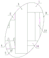
Fig. 1 is a schematic structural view of a tow tension buffering device for chemical fiber production according to the present invention.
Fig. 2 is an enlarged schematic structural diagram of a portion a of the tow tension buffering device for chemical fiber production according to the present invention.
Fig. 3 is an enlarged schematic structural diagram of a portion B of the tow tension buffering device for chemical fiber production according to the present invention.
In the figure: 1. a first rotating lever; 2. a second rotating lever; 3. a first metal plate; 4. a telescopic rod; 5. a buffer spring; 6. a sliding plate; 7. a limiting plate; 8. an anti-skid plate; 9. rotating the tube; 10. a limiting pipe; 11. a threaded rod; 12. a knob; 13. a second stabilizer bar; 14. a first stabilizer bar.
Detailed Description
The technical solutions in the embodiments of the present invention will be described clearly and completely with reference to the accompanying drawings in the embodiments of the present invention, and it is obvious that the described embodiments are only some embodiments of the present invention, not all embodiments. Based on the embodiments in the present invention, all other embodiments obtained by a person skilled in the art without creative work belong to the protection scope of the present invention.
Please refer to fig. 1-3, in the embodiment of the utility model, a tow tension buffer device for chemical fiber production, including two first dwang 1, the first metal sheet 3 of fixedly connected with is distinguished to one side that two first dwang 1 are relative, the common fixedly connected with second dwang 2 of one side that two first metal sheet 3 are relative, the outer wall left and right sides of two second dwang 2 sliding connection respectively has spacing pipe 10, threaded connection respectively is distinguished to the upper and lower both sides of two spacing pipes 10 has a fixed establishment, fixedly connected with limiting plate 7 is distinguished to one side that two spacing pipes 10 are relative, the upper and lower both sides difference fixedly connected with bleeder mechanism of one side that two first metal sheet 3 are relative, can be spacing well through limiting plate 7.
It should be introduced that fixed establishment includes threaded rod 11, threaded rod 11 and spacing pipe 10 threaded connection, and the other end fixedly connected with knob 12 of threaded rod 11, and the outer wall of knob 12 is carved with anti-skidding line, can be through knob 12 screw threaded rod 11 well.
In addition, the bleeder mechanism includes telescopic link 4, and one side of telescopic link 4 and the lateral wall fixed connection of first metal sheet 3, the other end fixedly connected with sliding plate 6 of telescopic link 4, the other end of sliding plate 6 and the corresponding lateral wall sliding connection of limiting plate 7 can stretch out and draw back well through telescopic link 4.
And, the outer wall of telescopic link 4 is around being connected with buffer spring 5, and one side of buffer spring 5 and the lateral wall fixed connection of corresponding sliding plate 6, the other end of buffer spring 5 and the lateral wall fixed connection of the adjacent first metal sheet 3 can cushion the power of unloading well through buffer spring 5.
It is worth mentioning that, the common sliding connection of one side that two limiting plate 7 are relative has rotating tube 9, and one side that two limiting plate 7 are relative fixedly connected with antiskid ribbed tile 8 respectively can be through antiskid ribbed tile 8 antiskid well.
Referring to fig. 1, the upper and lower sides of the opposite sides of the two first metal plates 3 are respectively and fixedly connected with a first stabilizer bar 14, the outer walls of the first stabilizer bars 14 are fixedly connected with a second stabilizer bar 13, and the other sides of the second stabilizer bars 13 are respectively and fixedly connected with the outer walls of the adjacent first rotating rods 1, so that the stabilizing effect can be greatly increased by the second stabilizer bars 13.
The utility model discloses a theory of operation is:
at the time of in-service use, at first select rotating knob 12, thereby it is spacing to carry out through threaded rod 11 and spacing pipe 10, first dwang 1 begins to rotate, thereby it begins to rotate to drive first metal sheet 3 on second stabilizer bar 13 and the first stabilizer bar 14, then it begins to rotate to drive second dwang 2, second dwang 2 drives limiting plate 7 and antiskid ribbed tile 8 and rotating tube 9 and begins to rotate, at the rotation in-process, telescopic link 4 and buffer spring 5's state changes, and begin to slide through sliding plate 6, thereby carry out tension buffering to the silk bundle.
Although the present invention has been described in detail with reference to the foregoing embodiments, it will be apparent to those skilled in the art that modifications may be made to the embodiments or portions thereof without departing from the spirit and scope of the invention.
Claims (6)
1. The utility model provides a silk bundle tension buffer for chemical fiber production, includes two first dwang (1), its characterized in that, two first dwang (1) one side relative is the first metal sheet of fixedly connected with (3), two the common fixedly connected with second dwang (2) in one side that first metal sheet (3) is relative, two the outer wall left and right sides of second dwang (2) sliding connection respectively has spacing pipe (10), two the upper and lower both sides of spacing pipe (10) threaded connection respectively have a fixed establishment, two one side relative of spacing pipe (10) is fixedly connected with limiting plate (7) respectively, two the upper and lower both sides difference fixedly connected with partial pressure mechanism of one side relative of first metal sheet (3).
2. The tow tension buffering device for chemical fiber production according to claim 1, wherein the fixing mechanism comprises a threaded rod (11), the threaded rod (11) is in threaded connection with the limiting tube (10), the other end of the threaded rod (11) is fixedly connected with a knob (12), and the outer wall of the knob (12) is carved with anti-skid grains.
3. The tow tension buffering device for chemical fiber production according to claim 1, wherein the pressure-dividing mechanism comprises a telescopic rod (4), one side of the telescopic rod (4) is fixedly connected with the side wall of the first metal plate (3), the other end of the telescopic rod (4) is fixedly connected with a sliding plate (6), and the other end of the sliding plate (6) is slidably connected with the side wall of the corresponding limiting plate (7).
4. The tow tension buffering device for chemical fiber production according to claim 3, wherein the outer wall of the telescopic rod (4) is wound with a buffering spring (5), one side of the buffering spring (5) is fixedly connected with the side wall of the corresponding sliding plate (6), and the other end of the buffering spring (5) is fixedly connected with the side wall of the adjacent first metal plate (3).
5. The tow tension buffering device for chemical fiber production according to claim 1, wherein a rotating tube (9) is connected to one side of each of the two limiting plates (7) in a sliding manner, and an anti-slip plate (8) is fixedly connected to one side of each of the two limiting plates (7).
6. The tow tension buffering device for chemical fiber production according to claim 1, wherein the two first metal plates (3) are fixedly connected with a first stabilizer bar (14) respectively at the upper side and the lower side of the opposite side, the outer walls of the first stabilizer bars (14) are fixedly connected with a second stabilizer bar (13), and the other sides of the second stabilizer bars (13) are fixedly connected with the outer walls of the adjacent first rotating rods (1) respectively.
Priority Applications (1)
| Application Number | Priority Date | Filing Date | Title |
|---|---|---|---|
| CN202121500597.8U CN215047656U (en) | 2021-07-02 | 2021-07-02 | Tow tension buffering device for chemical fiber production |
Applications Claiming Priority (1)
| Application Number | Priority Date | Filing Date | Title |
|---|---|---|---|
| CN202121500597.8U CN215047656U (en) | 2021-07-02 | 2021-07-02 | Tow tension buffering device for chemical fiber production |
Publications (1)
| Publication Number | Publication Date |
|---|---|
| CN215047656U true CN215047656U (en) | 2021-12-07 |
Family
ID=79227194
Family Applications (1)
| Application Number | Title | Priority Date | Filing Date |
|---|---|---|---|
| CN202121500597.8U Active CN215047656U (en) | 2021-07-02 | 2021-07-02 | Tow tension buffering device for chemical fiber production |
Country Status (1)
| Country | Link |
|---|---|
| CN (1) | CN215047656U (en) |
-
2021
- 2021-07-02 CN CN202121500597.8U patent/CN215047656U/en active Active
Similar Documents
| Publication | Publication Date | Title |
|---|---|---|
| CN104120525A (en) | Ultra-high molecular weight PE yarn and processing method thereof | |
| CN201560017U (en) | Winding tension bracket | |
| CN203333070U (en) | Terylene rope winding device | |
| CN215047656U (en) | Tow tension buffering device for chemical fiber production | |
| CN202323215U (en) | Dust cleaning device on spinning frame | |
| CN202830259U (en) | Device special for filament separation of spandex | |
| CN201201990Y (en) | Small-sized blowing-carding unit for experiment | |
| CN202717889U (en) | Silk hanging structure for nylon production | |
| CN204918893U (en) | Twisting frame fishing net silk antiskid device that falls | |
| CN203229617U (en) | Novel stripping knife for carding machine | |
| CN201420142Y (en) | Warping device and warping shaft | |
| CN202296587U (en) | Yarn correcting mechanism | |
| CN106757574A (en) | A kind of spinning, drawing device with effect of gathering | |
| CN202913095U (en) | Silk processing equipment | |
| CN102877162B (en) | Composite roving and tail yarn opener | |
| CN204608264U (en) | A kind of Fancy yarn spinning machines enter yarn feeding device | |
| CN204752993U (en) | Apparatus for preparing warp | |
| CN219906569U (en) | Yarn frame for spinning | |
| CN216947618U (en) | Eight-strand rope of stretch-proof polypropylene filament | |
| CN203462346U (en) | High-strength high-modulus polyvinyl acetate (PVA) fiber based stranded rope | |
| CN214989262U (en) | Thick fishing net fibre packing apparatus is used in fishing net production | |
| CN212374583U (en) | Multi-strand chemical fiber combining device | |
| CN205998767U (en) | Long yarn cable machine | |
| CN213387167U (en) | Chemical fiber yarn winding device | |
| CN201857449U (en) | Fine-denier spinning yarn finishing device |
Legal Events
| Date | Code | Title | Description |
|---|---|---|---|
| GR01 | Patent grant | ||
| GR01 | Patent grant |