CN215032670U - Punch press device for cable bridge - Google Patents
Punch press device for cable bridge Download PDFInfo
- Publication number
- CN215032670U CN215032670U CN202120727825.9U CN202120727825U CN215032670U CN 215032670 U CN215032670 U CN 215032670U CN 202120727825 U CN202120727825 U CN 202120727825U CN 215032670 U CN215032670 U CN 215032670U
- Authority
- CN
- China
- Prior art keywords
- plate
- fixing block
- rod
- punch press
- fixing
- Prior art date
- Legal status (The legal status is an assumption and is not a legal conclusion. Google has not performed a legal analysis and makes no representation as to the accuracy of the status listed.)
- Expired - Fee Related
Links
- 230000007246 mechanism Effects 0.000 claims abstract description 12
- 230000005540 biological transmission Effects 0.000 claims description 3
- 230000008878 coupling Effects 0.000 claims description 3
- 238000010168 coupling process Methods 0.000 claims description 3
- 238000005859 coupling reaction Methods 0.000 claims description 3
- 239000002184 metal Substances 0.000 abstract description 17
- 238000004080 punching Methods 0.000 abstract description 5
- 238000005516 engineering process Methods 0.000 abstract description 2
- 230000006835 compression Effects 0.000 description 2
- 238000007906 compression Methods 0.000 description 2
- 230000006872 improvement Effects 0.000 description 2
- 230000009286 beneficial effect Effects 0.000 description 1
- 238000010030 laminating Methods 0.000 description 1
- 238000000034 method Methods 0.000 description 1
- 230000008569 process Effects 0.000 description 1
- 230000009467 reduction Effects 0.000 description 1
Images


Abstract
The utility model discloses a punch press device for cable testing bridge relates to cable testing bridge processing technology field. This a punch press device for cable testing bridge, be provided with drive mechanism outside the top including the bottom plate, the fixed surface installs the side backup pad in the top of bottom plate, one side inner wall fixed mounting of side backup pad has the lower mould fixed plate, fixed mounting has the lower bolster on the lower mould fixed plate, the spout has been seted up to one side inner wall of side backup pad, slidable mounting has the slider in the spout, the bottom plate is provided with cope match-plate pattern and cylinder ejector pin through drive mechanism. This practicality can be convenient for the workman and take the cable testing bridge that the punching press is good, and the technical problem hard again consuming time when having solved the drawing of patterns to a certain extent has still improved work efficiency, and the condition that misoperation leads to cable testing bridge metal sheet to warp when having prevented workman's drawing of patterns takes place, and indirect reduce the cost has improved the efficiency of punch press device processing.
Description
Technical Field
The utility model relates to a cable testing bridge processing technology field specifically is a punch press device for cable testing bridge.
Background
The press machine is a press type press machine which deforms and processes a metal into a desired pattern by utilizing ductility of the metal and using a pressure for a die. At present, partial cable testing bridge punch press device can lead to the metal integrated circuit board that the compression is good in the mould, needs artifical manual operation to go the operation and takes out, potential safety hazard when having increased workman's operation, and work is consuming time again hard, and general manual drawing misoperation very big probably leads to the model to warp, causes the loss of cost.
SUMMERY OF THE UTILITY MODEL
An object of the utility model is to provide a punch press device for cable testing bridge to solve the problem that proposes among the above-mentioned background art.
In order to achieve the above object, the utility model provides a following technical scheme: the utility model provides a punch press device for cable testing bridge, comprising a base plate, the top surface fixed mounting of bottom plate has the bow-shaped board, be provided with drive mechanism on the bow-shaped board, the top surface fixed mounting of bottom plate has the side backup pad, one side inner wall fixed mounting of side backup pad has the lower mould fixed plate, fixed mounting has the lower bolster on the lower mould fixed plate, the spout has been seted up to one side inner wall of side backup pad, slidable mounting has the slider in the spout, the bottom plate is provided with cope match-plate pattern and cylinder ejector pin through drive mechanism.
Preferably, drive mechanism is including an upper fixed die plate, including a motor, an end cap, a controller, and a cover plate, the threaded rod, the slide bar, first fixed block, the second fixed block, the bracing piece, ejector pin fixed plate and upper fixed die plate, the threaded rod is installed in the inboard top and the inboard bottom rotation of bow-shaped plate, the inboard top and the inboard bottom fixed mounting of bow-shaped plate have the slide bar, the top fixed surface of bow-shaped plate installs the motor, the output shaft of motor run through the bow-shaped plate through the shaft coupling and with the top fixed connection of threaded rod, be provided with first fixed block and second fixed block on threaded rod and the slide bar, one side outer wall fixed mounting of first fixed block has an upper fixed die plate, one side outer wall fixed mounting of second fixed block has the bracing piece, one side outer wall fixed mounting of bracing piece has ejector pin fixed plate.
Preferably, the sliding groove in the side supporting plate is positioned at the upper end of the inner wall of one side of the side supporting plate, the bottom of the sliding groove formed in the side supporting plate is level with the height of the lower template, and the upper template can be controlled to be just attached to the lower template, so that the shape of the model is more accurate.
Preferably, the outer surface of the bottom of the upper die fixing plate is fixedly provided with an upper die plate, one side of the upper die fixing plate is fixedly connected with one side of the sliding block, and the outer surface of the top of the ejector rod fixing plate is fixedly provided with a cylindrical ejector rod.
Preferably, the number of the cylindrical ejector rods is four, the top of each cylindrical ejector rod penetrates through the lower die fixing plate and extends into the hole in the bottom of the lower die plate, and the diameter of the hole in the bottom of the lower die plate is larger than that of the cylindrical ejector rod, so that the cylindrical ejector rods can smoothly penetrate through the lower die plate to eject the metal plate of the cable bridge.
Preferably, the threaded rod runs through first fixed block and second fixed block and sets up with first fixed block and second fixed block threaded connection, and the slide bar runs through first fixed block and second fixed block and is connected the setting with first fixed block and second fixed block slide, can control cope match-plate pattern and cylinder ejector pin simultaneous movement simultaneously, and it is ejecting with the metal sheet of cable testing bridge after the mould compression is good to go up, accomplishes the great improvement work efficiency of operation in step.
Compared with the prior art, the beneficial effects of the utility model are that:
this a punch press device for cable testing bridge, through the punch plate, including a motor, an end cap, a controller, and a cover plate, the threaded rod, the slide bar, first fixed block, the second fixed block, the bracing piece, the cooperation of ejector pin fixed plate and cylinder ejector pin is used, release the cable testing bridge metal sheet from the lower bolster, the good cable testing bridge of punching press is taken to the workman of being convenient for, consuming time and hard technical problem when having solved the drawing of patterns to a certain extent, still improved work efficiency, the improper condition that leads to cable testing bridge metal sheet to warp when having prevented workman's drawing of patterns takes place, indirect reduce the cost.
Drawings
Fig. 1 is a schematic structural view of the present invention;
FIG. 2 is a front view of the present invention;
fig. 3 is a left side view of the lower template of the present invention;
fig. 4 is an enlarged view of the part a of the present invention.
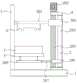
In the figure: the device comprises a base plate 1, a transmission mechanism 2, a side supporting plate 3, an upper die fixing plate 201, a motor 202, a threaded rod 203, a sliding rod 204, a first fixing block 205, a second fixing block 206, a supporting rod 207, a mandril fixing plate 208, a lower die fixing plate 4, a sliding block 5, an upper die plate 6, a lower die plate 7, a cylindrical mandril 8 and a bow-shaped plate 9.
Detailed Description
The technical solutions in the embodiments of the present invention will be described clearly and completely with reference to the accompanying drawings in the embodiments of the present invention, and it is obvious that the described embodiments are only some embodiments of the present invention, not all embodiments. Based on the embodiments in the present invention, all other embodiments obtained by a person skilled in the art without creative work belong to the protection scope of the present invention.
The first embodiment is as follows:
referring to fig. 1-4, the present invention provides a technical solution: the utility model provides a punch press device for cable testing bridge, comprising a base plate 1, bottom plate 1's top surface fixed mounting has bow-shaped board 9, be provided with drive mechanism 2 on the bow-shaped board 9, bottom plate 1's top surface fixed mounting has side backup pad 3, one side inner wall fixed mounting of side backup pad 3 has lower fixed die plate 4, fixed mounting has lower bolster 7 on the lower fixed die plate 4, spout on the side backup pad 3 is located one side inner wall upper end of side backup pad 3, the bottom of the spout that side backup pad 3 was seted up is leveled mutually with the height of lower bolster 7, can control cope match-plate pattern 6 and just make the shape of model with lower bolster 7 laminating mutually more accurate, the spout has been seted up to one side inner wall of side backup pad 3, slidable mounting has slider 5 in the spout, bottom plate 1 is provided with cope match-plate pattern 6 and cylinder ejector pin 8 through drive mechanism 2.
Furthermore, the number of the cylindrical ejector rods 8 is four, the top of each cylindrical ejector rod 8 penetrates through the lower die fixing plate 4 and extends into the hole in the inner side of the bottom of the lower die plate 7, and the diameter of the hole in the inner side of the bottom of the lower die plate 7 is larger than that of the cylindrical ejector rods 8.
Example two:
referring to fig. 1-4, on the basis of the first embodiment, the transmission mechanism 2 includes an upper mold fixing plate 201, a motor 202, a threaded rod 203, a sliding rod 204, a first fixing block 205, a second fixing block 206, a support rod 207 and a push rod fixing plate 208, the threaded rod 203 is rotatably installed at the top and bottom of the inner side of the upper mold fixing plate 201, the sliding rod 204 is fixedly installed at the top and bottom of the inner side of the arcuate plate 9, the motor 202 is fixedly installed at the outer surface of the top of the arcuate plate 9, an output shaft of the motor 202 penetrates through the arcuate plate 9 through a coupling and is fixedly connected with the top end of the threaded rod 203, the threaded rod 203 and the sliding rod 204 are provided with the first fixing block 205 and the second fixing block 206, the threaded rod 203 penetrates through the first fixing block 205 and the second fixing block 206 and is in threaded connection with the first fixing block 205 and the second fixing block 206, the sliding rod 204 penetrates through the first fixing block 205 and the second fixing block 206 and is connected with the first fixing block 205 and the second fixing block 206, an upper die fixing plate 201 is fixedly installed on the outer wall of one side of a first fixing block 205, a supporting rod 207 is fixedly installed on the outer wall of one side of a second fixing block 206, an ejector rod fixing plate 208 is fixedly installed on the outer wall of one side of the supporting rod 207, an upper die plate 6 is fixedly installed on the outer surface of the bottom of the upper die fixing plate 201, one side of the upper die fixing plate 201 is fixedly connected with one side of a sliding block 5, a cylindrical ejector rod 8 is fixedly installed on the outer surface of the top of the ejector rod fixing plate 208, a required cable bridge metal plate is placed on a lower die plate 7, a motor 202 is controlled to start to rotate in the forward direction, the motor 202 rotates in the forward direction to drive a threaded rod 203 to rotate, the threaded rod 203 drives the first fixing block 205 and the second fixing block 206 to move downwards, the first fixing block 205 moves downwards to drive the upper die fixing plate 201 and the upper die plate 6 to move downwards together, meanwhile, the upper die fixing plate 201 drives the sliding block 5 to move downwards in a sliding groove, and simultaneously, the threaded rod 203 rotates to drive the second fixing block 206 to move downwards, the second fixed block 206 moves to drive the supporting rod 207 to move downwards, the supporting rod 207 moves to drive the ejector rod fixing plate 208 to move downwards, the ejector rod fixing plate 208 moves to drive the cylindrical ejector rod 8 to move downwards, the upper template 6 and the cylindrical ejector rod 8 can be controlled to move simultaneously, after punching is completed, the motor 202 is controlled to rotate reversely, the motor 202 rotates forwards to drive the threaded rod 203 to rotate, the threaded rod 203 rotates to drive the first fixed block 205 and the second fixed block 206 to move upwards, the first fixed block 205 moves upwards to drive the upper template 201 and the upper template 6 to move upwards together, meanwhile, the upper template 201 drives the sliding block 5 to move upwards in the sliding chute, meanwhile, the threaded rod 203 rotates to drive the second fixed block 206 to move upwards, the second fixed block 206 moves to drive the supporting rod 207 to move upwards, the supporting rod 207 moves to drive the ejector rod fixing plate 208 to move upwards, the ejector rod fixing plate 208 moves to drive the cylindrical ejector rod 8 to move upwards, the inside that cylinder ejector pin 8 rebound passed through lower mould fixed plate 4 and lower bolster 7 moves the metal bottom to the cable testing bridge, cylinder ejector pin 8 rebound pushes out cable testing bridge metal sheet, accomplish the great improvement work efficiency of operation in step, and after having compressed the metal sheet, release cable testing bridge metal sheet from the mould, the workman of being convenient for takes the cable testing bridge that the punching press is good, the technical problem consuming time and hard when having solved the drawing of patterns to a certain extent, still improved work efficiency, improper operation when having prevented the workman and having leaded to the condition emergence of cable testing bridge metal sheet deformation, indirect reduction of cost.
The working principle is as follows: placing a required cable bridge metal plate on a lower template 7, controlling a motor 202 to start forward rotation, driving a threaded rod 203 to rotate by forward rotation of the motor 202, driving a first fixed block 205 and a second fixed block 206 to move downwards by rotation of the threaded rod 203, driving an upper die fixing plate 201 and an upper die plate 6 to move downwards by downward movement of the first fixed block 205, driving a slider 5 to move downwards in a sliding chute by the upper die fixing plate 201, driving a second fixed block 206 to move downwards by rotation of the threaded rod 203, driving a supporting rod 207 to move downwards by movement of the second fixed block 206, driving a mandril fixing plate 208 to move downwards by movement of the supporting rod 207, driving a cylindrical mandril 8 to move downwards by movement of the mandril fixing plate 208, controlling the motor 202 to rotate reversely after punching is completed, driving the threaded rod 203 to rotate by forward rotation of the motor 202, driving the first fixed block 205 and the second fixed block 206 to move upwards by rotation of the threaded rod 203, driving the upper die fixing plate 201 and the upper die plate 6 to move upwards together by upward movement of the first fixed block 205, meanwhile, the upper die fixing plate 201 drives the sliding block 5 to move upwards in the sliding groove, meanwhile, the threaded rod 203 rotates to drive the second fixing block 206 to move upwards, the second fixing block 206 moves to drive the supporting rod 207 to move upwards, the supporting rod 207 moves to drive the ejector rod fixing plate 208 to move upwards, the ejector rod fixing plate 208 moves to drive the cylindrical ejector rod 8 to move upwards, the cylindrical ejector rod 8 moves upwards to move to the metal bottom of the cable bridge through the lower die fixing plate 4 and the lower die plate 7, and the cylindrical ejector rod 8 moves upwards to eject the cable bridge metal plate.
Claims (6)
1. A punch press device for cable testing bridge, includes bottom plate (1), its characterized in that: the top surface fixed mounting of bottom plate (1) has bow-shaped board (9), be provided with drive mechanism (2) on bow-shaped board (9), the top surface fixed mounting of bottom plate (1) has side backup pad (3), one side inner wall fixed mounting of side backup pad (3) has lower fixed plate (4), fixed mounting has lower bolster (7) on lower fixed plate (4), the spout has been seted up to one side inner wall of side backup pad (3), slidable mounting has slider (5) in the spout, bottom plate (1) is provided with cope match-plate pattern (6) and cylinder ejector pin (8) through drive mechanism (2).
2. The punch press apparatus for a cable tray of claim 1, wherein: the transmission mechanism (2) comprises an upper die fixing plate (201), a motor (202), a threaded rod (203), a sliding rod (204), a first fixing block (205), a second fixing block (206), a supporting rod (207) and an ejector rod fixing plate (208), the threaded rod (203) is rotatably installed at the top and the bottom of the inner side of the arched plate (9), the sliding rod (204) is fixedly installed at the top and the bottom of the inner side of the arched plate (9), the motor (202) is fixedly installed on the outer surface of the top of the arched plate (9), an output shaft of the motor (202) penetrates through the arched plate (9) through a shaft coupling and is fixedly connected with the top end of the threaded rod (203), the first fixing block (205) and the second fixing block (206) are arranged on the threaded rod (203) and the sliding rod (204), the upper die fixing plate (201) is fixedly installed on the outer wall of one side of the first fixing block (205), the supporting rod (207) is fixedly installed on the outer wall of one side of the second fixing block (206), and the outer wall of one side of the supporting rod (207) is fixedly provided with an ejector rod fixing plate (208).
3. The punch press apparatus for a cable tray of claim 1, wherein: the sliding groove in the side supporting plate (3) is positioned at the upper end of the inner wall of one side of the side supporting plate (3), and the bottom of the sliding groove formed in the side supporting plate (3) is level with the height of the lower template (7).
4. The punch press apparatus for a cable tray of claim 2, wherein: the outer fixed surface in bottom of last mold fixing plate (201) installs cope match-plate pattern (6), and one side of last mold fixing plate (201) and one side fixed connection of slider (5), the outer fixed surface in top of ejector pin fixed plate (208) installs cylinder ejector pin (8).
5. The punch press apparatus for a cable tray of claim 1, wherein: the number of the cylindrical ejector rods (8) is four, the top of each cylindrical ejector rod (8) penetrates through the lower die fixing plate (4) and extends into the hole in the bottom of the lower die plate (7), and the diameter of the hole in the bottom of the lower die plate (7) is larger than that of the cylindrical ejector rods (8).
6. The punch press apparatus for a cable tray of claim 2, wherein: the threaded rod (203) penetrates through the first fixing block (205) and the second fixing block (206) and is in threaded connection with the first fixing block (205) and the second fixing block (206), and the sliding rod (204) penetrates through the first fixing block (205) and the second fixing block (206) and is in sliding connection with the first fixing block (205) and the second fixing block (206).
Priority Applications (1)
| Application Number | Priority Date | Filing Date | Title |
|---|---|---|---|
| CN202120727825.9U CN215032670U (en) | 2021-04-12 | 2021-04-12 | Punch press device for cable bridge |
Applications Claiming Priority (1)
| Application Number | Priority Date | Filing Date | Title |
|---|---|---|---|
| CN202120727825.9U CN215032670U (en) | 2021-04-12 | 2021-04-12 | Punch press device for cable bridge |
Publications (1)
| Publication Number | Publication Date |
|---|---|
| CN215032670U true CN215032670U (en) | 2021-12-07 |
Family
ID=79148547
Family Applications (1)
| Application Number | Title | Priority Date | Filing Date |
|---|---|---|---|
| CN202120727825.9U Expired - Fee Related CN215032670U (en) | 2021-04-12 | 2021-04-12 | Punch press device for cable bridge |
Country Status (1)
| Country | Link |
|---|---|
| CN (1) | CN215032670U (en) |
-
2021
- 2021-04-12 CN CN202120727825.9U patent/CN215032670U/en not_active Expired - Fee Related
Similar Documents
| Publication | Publication Date | Title |
|---|---|---|
| CN106270249B (en) | A kind of stamping parts feeding material collecting device and feeding rewinding method | |
| CN212917275U (en) | Stamping die with location anticreep function | |
| CN215032670U (en) | Punch press device for cable bridge | |
| CN113732106A (en) | Automatic hot trimmer for hardware machining | |
| CN211915293U (en) | Press machine with blanking device | |
| CN216466783U (en) | Automatic silk screen printing device is used in processing of silica gel toy | |
| CN108543869A (en) | The two-sided hydraulic stamping mold of automatic demoulding | |
| CN215237223U (en) | Novel auto-parts mould | |
| CN214290409U (en) | Mold with stripper plate | |
| CN212598363U (en) | Punch press is used in production of elevator sill | |
| CN212144210U (en) | Sub vehicle frame hypoplastron stamping die before car | |
| CN112620451A (en) | Metal equipment stamping equipment and processing method thereof | |
| CN208392016U (en) | A kind of mechanical processing machine feeding device | |
| CN220406779U (en) | Stamping device for machine-building | |
| CN217451819U (en) | Automatic die sinking stamping device | |
| CN215965637U (en) | Aluminum alloy shaping hydraulic press | |
| CN220028479U (en) | Automatic ejection device for stamping forming of sheet metal parts | |
| CN211360236U (en) | Multi-station punch forming machine | |
| CN219817715U (en) | Stamping die with waste ejection detection device | |
| CN213162549U (en) | Automatic go up unloading robot of bending | |
| CN212760701U (en) | Mould liftout device | |
| CN112165777B (en) | Board splitting mechanism of PCB | |
| CN220920971U (en) | Perforating machine convenient for feeding | |
| CN211938640U (en) | Push-pull feeding type starting cup punching device | |
| CN214281153U (en) | Motor rotor shaft sleeve press-in machine |
Legal Events
| Date | Code | Title | Description |
|---|---|---|---|
| GR01 | Patent grant | ||
| GR01 | Patent grant | ||
| CF01 | Termination of patent right due to non-payment of annual fee | ||
| CF01 | Termination of patent right due to non-payment of annual fee |
Granted publication date: 20211207 |