CN215030542U - Sizing machine for paper production - Google Patents
Sizing machine for paper production Download PDFInfo
- Publication number
- CN215030542U CN215030542U CN202120834694.4U CN202120834694U CN215030542U CN 215030542 U CN215030542 U CN 215030542U CN 202120834694 U CN202120834694 U CN 202120834694U CN 215030542 U CN215030542 U CN 215030542U
- Authority
- CN
- China
- Prior art keywords
- plate
- fixedly connected
- rotating shaft
- rotating
- paper production
- Prior art date
- Legal status (The legal status is an assumption and is not a legal conclusion. Google has not performed a legal analysis and makes no representation as to the accuracy of the status listed.)
- Expired - Fee Related
Links
- 238000004513 sizing Methods 0.000 title claims abstract description 42
- 238000004519 manufacturing process Methods 0.000 title claims abstract description 19
- 239000003292 glue Substances 0.000 claims abstract description 52
- 239000007788 liquid Substances 0.000 claims abstract description 7
- 238000009499 grossing Methods 0.000 claims description 7
- 238000003860 storage Methods 0.000 claims description 5
- 230000000903 blocking effect Effects 0.000 claims description 4
- 230000005540 biological transmission Effects 0.000 claims description 3
- 238000007790 scraping Methods 0.000 claims 3
- 238000000605 extraction Methods 0.000 abstract description 3
- 239000003973 paint Substances 0.000 abstract description 2
- 238000004026 adhesive bonding Methods 0.000 description 9
- 230000000694 effects Effects 0.000 description 6
- 238000010073 coating (rubber) Methods 0.000 description 4
- 238000007599 discharging Methods 0.000 description 3
- 230000009286 beneficial effect Effects 0.000 description 2
- 230000006978 adaptation Effects 0.000 description 1
- 230000007812 deficiency Effects 0.000 description 1
- 230000000704 physical effect Effects 0.000 description 1
- 239000007921 spray Substances 0.000 description 1
- 230000000087 stabilizing effect Effects 0.000 description 1
- 238000004381 surface treatment Methods 0.000 description 1
Images


Landscapes
- Coating Apparatus (AREA)
Abstract
The utility model discloses a sizing applicator for paper production relates to papermaking equipment technical field, including the mounting bracket, the top of mounting bracket is provided with moves sizing mechanism and decides sizing mechanism, moves sizing mechanism and decides the below of sizing mechanism and all is provided with collection mechanism and lower gluey mechanism, and the upper surface of mounting bracket articulates there are two symmetrical electric liquid push rods. The utility model relates to a rational in infrastructure, it can utilize the rotation of axis of rotation will together drive the rotation of cross pivot through the belt, make the rotation of cross pivot will drive the live-rollers rotation, because electric putter's flexible end is connected for rotating with the live-rollers, therefore electric putter's operation can drive the live-rollers and slide in the cross pivot, further messenger stores up the glue solution in the gluey incasement and discharges from going out the rubber tube under the extraction of the pump body, the glue solution will drip to the live-rollers after that, make the live-rollers also at reciprocating motion when rotatory, and then can be more even paint on the rubber applying roller of glue solution.
Description
Technical Field
The utility model relates to a papermaking equipment technical field specifically is a sizing applicator is used in paper production.
Background
With the increasing demand of paper, papermaking equipment is gradually developed, so that the production efficiency of the paper is improved, the quality of the paper is also improved, the produced paper needs to be subjected to surface treatment, generally sizing treatment, and the purpose of surface sizing is generally to prevent liquid from permeating, so that better surface performance is obtained to improve the physical properties of the paper.
At present, most of glue solutions on two applicator rollers are directly sprayed on the applicator rollers through a spray head, and the glue solutions are difficult to be uniformly adhered on the applicator rollers, so that excessive or insufficient glue solutions exist on the surfaces of the applicator rollers, further, the paper is not uniformly coated, and the production and processing quality of the paper is reduced. Therefore, the sizing machine for paper production is provided to solve the problems.
SUMMERY OF THE UTILITY MODEL
One) technical problem to be solved
The utility model aims at providing a sizing applicator for paper production in order to compensate the deficiency of the prior art.
II) technical scheme
In order to achieve the above object, the utility model provides a following technical scheme: the utility model provides a sizing machine for paper production, includes the mounting bracket, and the top of mounting bracket is provided with moves sizing mechanism and decides sizing mechanism, moves sizing mechanism and decides the below of sizing mechanism and all is provided with collection mechanism and lower gluey mechanism, and the upper surface of mounting bracket articulates there are two symmetrical electric liquid push rods.
Further, move sizing mechanism and include two symmetrical rotor plates, decide sizing mechanism and include two symmetrical fixed plates, every rotor plate all articulates in the upper surface of mounting bracket, and every fixed plate is all fixed connection in the upper surface of mounting bracket.
Furthermore, move sizing mechanism and decide sizing mechanism and all include axis of rotation and sizing roller, and sizing roller fixed connection in the surface of axis of rotation, two axis of rotation rotate respectively and connect between two rotor plates and between two fixed plates, the equal fixedly connected with backup pad of the upper surface of every rotor plate and fixed plate, the top of every sizing roller all is provided with supporting platform, and supporting platform fixed connection in the upper surface of backup pad.
Further, the equal fixedly connected with two first risers of the surface of every fixed plate, the equal fixedly connected with second riser of the surface of every rotor plate, and first riser and second riser are connected with two supporting platform respectively, and the flexible end of two electric liquid push rods is articulated mutually with the surface of two second risers respectively.
Further, the equal fixedly connected with of upper surface of every supporting platform stores up gluey case, and the pump body is all installed to every supporting platform's upper surface, and the output of every pump body all is fixed the intercommunication has lower rubber tube, and the equal fixedly connected with rubber outlet pipe in bottom surface of every supporting platform, the input of two pump bodies is linked together with two storage gluey casees respectively, and two lower rubber tubes are linked together with two rubber outlet pipes respectively.
Further, collect the mechanism including collecting frame and scraper blade, collect frame fixed connection in the inner wall of mounting bracket, and collect the below that the frame is located the applicator roll, scraper blade fixed connection is in the upper surface of collecting the frame, and the surface and the applicator roll of scraper blade are close to mutually.
Further, lower gluey mechanism includes electric putter, live-rollers and cross pivot, electric putter installs in the inside of backup pad, and electric putter's flexible end run through the backup pad and with backup pad sliding connection, electric putter's flexible end is connected with the back of live-rollers rotation, live-rollers and cross pivot all are located the below of glue outlet pipe and are located the top of glue application roller, electric putter's one end is kept away from in the cross pivot is rotated with the backup pad and is connected, the axis of rotation passes through the belt and is connected with the transmission of cross pivot, the surface of cross pivot is located to the live-rollers cover, and live-rollers and cross pivot looks adaptation.
Furthermore, the bottom surface of each supporting platform is fixedly connected with a smoothing plate and a rubber blocking plate, the bottom surface of each smoothing plate is close to the applicator roll, and the outer surface of each rubber blocking plate is in contact with the rotating roll.
Thirdly), the beneficial effects are as follows:
compared with the prior art, the sizing machine for paper production has the following beneficial effects:
the utility model discloses an axis of rotation, backup pad and down glue under the cooperation between the mechanism, can utilize the rotation of axis of rotation will together drive the rotation of cross pivot through the belt, make the rotation of cross pivot will drive the live-rollers rotation, because electric putter's flexible end is connected for rotating with the live-rollers, consequently electric putter's operation can drive the live-rollers and slide in the cross pivot, further messenger stores up the glue solution of gluing incasement and discharges from going out the rubber tube under the extraction of the pump body, the glue solution will drip to the live-rollers after that, make the live-rollers also at reciprocating motion in rotatory, and can be more even more paint on the rubber applying roller of glue solution, thereby can be more even carry out the rubber coating to the paper.
Two, the utility model discloses a under the setting of collecting the mechanism, can strike off unnecessary glue solution through the scraper blade on the applicator roll, and strike off to collecting the frame extremely, so that collect, avoid too much glue solution to remain on the applicator roll always, and then guaranteed the glueing efficiency of paper, through pacifying dull and stereotyped setting, can smooth the glue solution after gluing down, and guaranteed the glueing effect to the paper, the effect even to the paper glueing has also been improved simultaneously, under the setting of fender offset plate, can avoid the glue solution of live-rollers when rotatory to splash.
Drawings
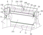
FIG. 1 is a schematic front view of the present invention;
FIG. 2 is a bottom partial sectional view of the present invention;
fig. 3 is a rear partial sectional view of the present invention;
fig. 4 is a left side partial sectional view of the present invention;
fig. 5 is an enlarged schematic view of a structure shown in fig. 4 according to the present invention.
In the figure: 1. a mounting frame; 100. a rotating shaft; 101. applying a rubber roll; 102. a support plate; 103. a support platform; 104. a glue storage box; 105. a pump body; 106. discharging a rubber tube; 107. discharging the rubber tube; 2. a movable glue applying mechanism; 21. a rotating plate; 22. a second vertical plate; 3. a glue sizing mechanism; 31. a fixing plate; 32. a first vertical plate; 4. a collection mechanism; 41. a collection frame; 42. a squeegee; 5. a glue feeding mechanism; 51. an electric push rod; 52. a rotating roller; 53. a cross-shaped rotating shaft; 6. flattening the plate; 7. an electro-hydraulic push rod; 8. keep off the offset plate.
Detailed Description
The technical solutions in the embodiments of the present invention will be described clearly and completely with reference to the accompanying drawings in the embodiments of the present invention, and it is obvious that the described embodiments are only some embodiments of the present invention, not all embodiments. Based on the embodiments in the present invention, all other embodiments obtained by a person skilled in the art without creative work belong to the protection scope of the present invention.
As shown in fig. 1-5, the utility model provides a technical solution: a sizing machine for paper production comprises a mounting frame 1, a movable sizing mechanism 2 and a fixed sizing mechanism 3 are arranged above the mounting frame 1, a collecting mechanism 4 and a sizing mechanism 5 are arranged below the movable sizing mechanism 2 and the fixed sizing mechanism 3, two symmetrical electric hydraulic push rods 7 are hinged to the upper surface of the mounting frame 1, the movable sizing mechanism 2 comprises two symmetrical rotating plates 21, the fixed sizing mechanism 3 comprises two symmetrical fixing plates 31, each rotating plate 21 is hinged to the upper surface of the mounting frame 1, the inclination angle of the movable sizing mechanism 2 can be conveniently adjusted, the sizing machine is further suitable for sizing paper with different thicknesses, each fixing plate 31 is fixedly connected to the upper surface of the mounting frame 1, the movable sizing mechanism 2 and the fixed sizing mechanism 3 respectively comprise a rotating shaft 100 and a sizing roller 101, the sizing roller 101 is fixedly connected to the outer surface of the rotating shaft 100, the two rotating shafts 100 are respectively rotatably connected between the two rotating plates 21 and between the two fixing plates 31, the upper surfaces of each rotating plate 21 and the fixed plate 31 are fixedly connected with a supporting plate 102, a supporting platform 103 is arranged above each glue applicator 101, the supporting platform 103 is fixedly connected to the upper surface of the supporting plate 102, the fixing effect of the supporting platform 103 can be effectively ensured, the outer surface of each fixed plate 31 is fixedly connected with two first vertical plates 32, the outer surface of each rotating plate 21 is fixedly connected with a second vertical plate 22, the first vertical plates 32 and the second vertical plates 22 are respectively connected with the two supporting platforms 103, the connecting and stabilizing effect of the supporting platforms 103 can be further improved, the telescopic ends of the two electric hydraulic push rods 7 are respectively hinged with the outer surfaces of the two second vertical plates 22, the inclination angle of the movable glue applicator mechanism 2 can be controlled by utilizing the operation of the two electric hydraulic push rods 7, so that glue applicators 101 can apply glue to paper with different thicknesses, the equal fixedly connected with of upper surface of every supporting platform 103 stores up gluey case 104, the interior diapire that stores up gluey case 104 is the inclined plane form, so that the discharge that the glue solution is more smooth, the pump body 105 is all installed to the upper surface of every supporting platform 103, the equal fixed intercommunication of output of every pump body 105 has lower rubber tube 106, the equal fixedly connected with rubber tube 107 in bottom surface of every supporting platform 103, the input of two pump bodies 105 is linked together with two storage gluey casees 104 respectively, two lower rubber tubes 106 are linked together with two rubber tube 107 respectively, can utilize the operation of the pump body 105 to extract the glue solution that stores up gluey incasement 104, and finally discharge through rubber tube 107, so that carry out the rubber coating to applicator roll 101.
The collecting mechanism 4 comprises a collecting frame 41 and a scraper 42, the collecting frame 41 is fixedly connected to the inner wall of the mounting frame 1, the collecting frame 41 is located below the applicator roll 101, the collecting scraper 42 can collect the glue scraped from the applicator roll 101 conveniently, the glue is prevented from dripping on the bottom surface, the scraper 42 is fixedly connected to the upper surface of the collecting frame 41, the outer surface of the scraper 42 is close to the applicator roll 101, the scraper 42 can scrape the redundant glue on the applicator roll 101, the excessive glue is effectively prevented from remaining on the applicator roll 101 all the time, the gluing efficiency of paper is further ensured, the glue discharging mechanism 5 comprises an electric push rod 51, a rotating roll 52 and a cross rotating shaft 53, the electric push rod 51 is arranged inside the supporting plate 102, the two electric push rods 51 are fixedly connected to the rear 21 and 31 respectively, and the telescopic end of the electric push rod 51 penetrates through the supporting plate 102 and is connected with the supporting plate 102 in a sliding manner, the telescopic end of the electric push rod 51 is rotatably connected with the back of the rotating roller 52, the rotating roller 52 and the cross rotating shaft 53 are both positioned below the rubber outlet pipe 107 and above the applicator roll 101, one end of the cross rotating shaft 53, which is far away from the electric push rod 51, is rotatably connected with the supporting plate 102, the rotating shaft 100 is in transmission connection with the cross rotating shaft 53 through a belt, the rotating roller 52 is sleeved on the outer surface of the cross rotating shaft 53, the rotating roller 52 is matched with the cross rotating shaft 53, the outer surface of the cross rotating shaft 53 is clamped with the inner wall of the rotating roller 52, meanwhile, the rotating roller 52 can slide on the cross rotating shaft 53, the rotation of the rotating shaft 100 drives the cross rotating shaft 53 and the rotating roller 52 to rotate together, and the rotating roller 52 can be pulled to reciprocate by the reciprocating operation of the electric push rod 51, so that the rubber liquid drops on the rotating roller 52, and the rubber liquid is more uniformly coated on the applicator roll 101, the convenience is evenly the rubber coating to the paper, cross pivot 53 is provided with the protection casing with the junction of axis of rotation 100, can effectually avoid the glue solution drippage on the belt, the effectual rotation effect of cross pivot 53 of having guaranteed simultaneously, the equal fixedly connected with in bottom surface of every supporting platform 103 smooths flat 6 and keeps off offset 8, the bottom surface of smoothing board 6 is close to with rubber application roller 101 mutually, the surface that keeps off offset 8 contacts with live-rollers 52, through the setting of smoothing flat 6, can smooth the glue solution after the time of gluing, and the glueing effect to the paper has been guaranteed, the even effect of paper glueing has also been improved simultaneously, under the setting of keeping off offset 8, can avoid the glue solution of live-rollers 52 when rotatory to splash.
The working principle is as follows: when paper is glued, a power supply of the electric push rod 51 and the pump body 105 is started, at the moment, the two rotating shafts 100 are driven by an external power source to rotate, so that the rotating shafts 100 can drive the cross rotating shaft 53 to rotate together through a belt while rotating, the rotating shaft 53 can drive the rotating roller 52 to rotate, the telescopic end of the electric push rod 51 is rotatably connected with the rotating roller 52, the rotating roller 52 can be driven to rotate and slide on the cross rotating shaft 53 by the operation of the electric push rod 51, glue in the glue storage tank 104 is further discharged from the glue outlet pipe 107 through the extraction of the pump body 105, the glue is enabled to be dripped and distributed on the rotating roller 52, the glue can be more uniformly smeared on the glue applicator roller 101, and under the arrangement of the smoothing plate 6, the glue smeared on the glue applicator roller 101 can be smoothed, so that the paper can be glued, thereby can be more even carry out the rubber coating to the paper, live-rollers 52 will throw away partial glue solution when rotatory removal, consequently under the setting of keep off offset plate 8, can effectually avoid the glue solution to splash, scraper blade 42 can be scraped the unnecessary glue solution on the applicator roll 101 to collection frame 41 in simultaneously, the phenomenon of unevenness appears in the glue solution on the effective applicator roll 101 of avoiding.
Claims (8)
1. A sizing machine for paper production comprises a mounting rack (1), and is characterized in that: the top of mounting bracket (1) is provided with and moves gluey mechanism (2) and gluey mechanism (3) of deciding, the below of moving gluey mechanism (2) and gluey mechanism (3) of deciding all is provided with collects mechanism (4) and gluey mechanism (5) down, the upper surface of mounting bracket (1) articulates there are two symmetrical electric liquid push rods (7).
2. A size press for paper production according to claim 1, characterized in that: move gluey mechanism (2) including two symmetrical rotor plates (21), gluey mechanism (3) of deciding includes two symmetrical fixed plates (31), every rotor plate (21) all articulates the upper surface in mounting bracket (1), every fixed plate (31) all fixed connection in the upper surface of mounting bracket (1).
3. A size press for paper production according to claim 2, characterized in that: the movable glue applying mechanism (2) and the fixed glue applying mechanism (3) respectively comprise a rotating shaft (100) and a glue applying roller (101), the glue applying roller (101) is fixedly connected to the outer surface of the rotating shaft (100), the two rotating shafts (100) are respectively and rotatably connected between two rotating plates (21) and between two fixing plates (31), a supporting plate (102) is fixedly connected to the upper surfaces of the rotating plates (21) and the fixing plates (31), a supporting platform (103) is arranged above each glue applying roller (101), and the supporting platform (103) is fixedly connected to the upper surface of the supporting plate (102).
4. A size press for paper production according to claim 3, characterized in that: the outer surface of each fixed plate (31) is fixedly connected with two first vertical plates (32), the outer surface of each rotating plate (21) is fixedly connected with a second vertical plate (22), the first vertical plates (32) and the second vertical plates (22) are respectively connected with two supporting platforms (103), and the telescopic ends of the two electro-hydraulic push rods (7) are respectively hinged to the outer surfaces of the two second vertical plates (22).
5. A size press for paper production according to claim 3, characterized in that: every the equal fixedly connected with of upper surface of supporting platform (103) stores up gluey case (104), every the pump body (105), every are all installed to the upper surface of supporting platform (103) the output of the pump body (105) all is fixed the intercommunication has lower rubber tube (106), every the equal fixedly connected with of bottom surface of supporting platform (103) goes out rubber tube (107), two the input of the pump body (105) is linked together with two storage gluey cases (104) respectively, two lower rubber tube (106) is linked together with two rubber tube (107) respectively.
6. A size press for paper production according to claim 3, characterized in that: the collecting mechanism (4) comprises a collecting frame (41) and a scraping plate (42), the collecting frame (41) is fixedly connected to the inner wall of the mounting frame (1), the collecting frame (41) is located below the applicator roll (101), the scraping plate (42) is fixedly connected to the upper surface of the collecting frame (41), and the outer surface of the scraping plate (42) is close to the applicator roll (101).
7. A size press for paper production according to claim 5, characterized in that: the glue feeding mechanism (5) comprises an electric push rod (51), a rotating roller (52) and a cross rotating shaft (53), the electric push rod (51) is arranged inside the supporting plate (102), and the telescopic end of the electric push rod (51) penetrates through the support plate (102) and is connected with the support plate (102) in a sliding way, the telescopic end of the electric push rod (51) is rotationally connected with the back of the rotating roller (52), the rotating roller (52) and the cross rotating shaft (53) are both positioned below the rubber outlet pipe (107) and above the applicator roller (101), one end of the cross rotating shaft (53) far away from the electric push rod (51) is rotationally connected with the supporting plate (102), the rotating shaft (100) is in transmission connection with the cross rotating shaft (53) through a belt, the rotating roller (52) is sleeved on the outer surface of the cross rotating shaft (53), and the rotating roller (52) is matched with the cross rotating shaft (53).
8. A size press for paper production according to claim 7, characterized in that: the bottom surface of each supporting platform (103) is fixedly connected with a smoothing plate (6) and a rubber blocking plate (8), the bottom surface of the smoothing plate (6) is close to the applicator roll (101), and the outer surface of the rubber blocking plate (8) is in contact with the rotating roll (52).
Priority Applications (1)
| Application Number | Priority Date | Filing Date | Title |
|---|---|---|---|
| CN202120834694.4U CN215030542U (en) | 2021-04-22 | 2021-04-22 | Sizing machine for paper production |
Applications Claiming Priority (1)
| Application Number | Priority Date | Filing Date | Title |
|---|---|---|---|
| CN202120834694.4U CN215030542U (en) | 2021-04-22 | 2021-04-22 | Sizing machine for paper production |
Publications (1)
| Publication Number | Publication Date |
|---|---|
| CN215030542U true CN215030542U (en) | 2021-12-07 |
Family
ID=79111614
Family Applications (1)
| Application Number | Title | Priority Date | Filing Date |
|---|---|---|---|
| CN202120834694.4U Expired - Fee Related CN215030542U (en) | 2021-04-22 | 2021-04-22 | Sizing machine for paper production |
Country Status (1)
| Country | Link |
|---|---|
| CN (1) | CN215030542U (en) |
Cited By (1)
| Publication number | Priority date | Publication date | Assignee | Title |
|---|---|---|---|---|
| CN117160768A (en) * | 2023-11-02 | 2023-12-05 | 南通图海机械有限公司 | But rubberizing mechanism of automatically regulated |
-
2021
- 2021-04-22 CN CN202120834694.4U patent/CN215030542U/en not_active Expired - Fee Related
Cited By (2)
| Publication number | Priority date | Publication date | Assignee | Title |
|---|---|---|---|---|
| CN117160768A (en) * | 2023-11-02 | 2023-12-05 | 南通图海机械有限公司 | But rubberizing mechanism of automatically regulated |
| CN117160768B (en) * | 2023-11-02 | 2024-03-08 | 南通图海机械有限公司 | But rubberizing mechanism of automatically regulated |
Similar Documents
| Publication | Publication Date | Title |
|---|---|---|
| CN215030542U (en) | Sizing machine for paper production | |
| CN215507510U (en) | Coating roller coating mechanism | |
| CN212041275U (en) | Plywood is with high-efficient rubber coating device | |
| CN210585552U (en) | Disc brake block processing is with mechanism of spraying paint | |
| CN210304325U (en) | Paint environmental protection processing system is used in wooden furniture production | |
| CN220678431U (en) | Multifunctional gluing device capable of uniformly coating | |
| CN218590991U (en) | Glue spreader convenient for production of mica tape electromagnetic wire | |
| CN208161950U (en) | Binding and printing machine brush coating drying unit | |
| CN216605829U (en) | Glue applying device for paper | |
| CN215518157U (en) | Paper machine glue applying device capable of uniformly applying glue | |
| CN211964815U (en) | Insulating board production coating equipment that glue coating is comparatively even | |
| CN213700540U (en) | Plate glue spreader capable of spreading glue on two sides | |
| CN215282404U (en) | Glue spreader for plywood | |
| CN209849173U (en) | Gluing device of compound machine | |
| CN214637751U (en) | Corrugated container board processing laminating auxiliary device | |
| CN216137529U (en) | Gluing device for processing hard light protective film | |
| CN221453124U (en) | PVC floor rubber coating device | |
| CN216834697U (en) | Laminating device for label manufacturing | |
| CN216125969U (en) | Double-sided gluing machine for seamless paper tube surface paper | |
| CN220879401U (en) | Novel foaming gum dipping box | |
| CN211031583U (en) | Simple and easy type wainscot machine | |
| CN221433751U (en) | Composite glue spreader for paperboard processing | |
| CN214088293U (en) | Glass surface film layer spraying device | |
| CN220177226U (en) | Gluing equipment for production of laminated paper tubes | |
| CN211993414U (en) | Novel bamboo board gluing machine |
Legal Events
| Date | Code | Title | Description |
|---|---|---|---|
| GR01 | Patent grant | ||
| GR01 | Patent grant | ||
| CF01 | Termination of patent right due to non-payment of annual fee |
Granted publication date: 20211207 |
|
| CF01 | Termination of patent right due to non-payment of annual fee |