CN215023979U - Remaining needle - Google Patents
Remaining needle Download PDFInfo
- Publication number
- CN215023979U CN215023979U CN202120625568.8U CN202120625568U CN215023979U CN 215023979 U CN215023979 U CN 215023979U CN 202120625568 U CN202120625568 U CN 202120625568U CN 215023979 U CN215023979 U CN 215023979U
- Authority
- CN
- China
- Prior art keywords
- dropper
- extension pipe
- liquid permeable
- section
- needle
- Prior art date
- Legal status (The legal status is an assumption and is not a legal conclusion. Google has not performed a legal analysis and makes no representation as to the accuracy of the status listed.)
- Expired - Fee Related
Links
- 230000000670 limiting effect Effects 0.000 claims abstract description 11
- 239000007788 liquid Substances 0.000 claims description 18
- 239000013013 elastic material Substances 0.000 claims description 3
- 238000000034 method Methods 0.000 abstract description 2
- 238000001802 infusion Methods 0.000 description 4
- 210000004204 blood vessel Anatomy 0.000 description 3
- 230000000694 effects Effects 0.000 description 2
- 229920003023 plastic Polymers 0.000 description 2
- 239000004033 plastic Substances 0.000 description 2
- 241000251468 Actinopterygii Species 0.000 description 1
- 239000002390 adhesive tape Substances 0.000 description 1
- 238000010586 diagram Methods 0.000 description 1
- 239000000463 material Substances 0.000 description 1
- 239000012528 membrane Substances 0.000 description 1
- 238000012986 modification Methods 0.000 description 1
- 230000004048 modification Effects 0.000 description 1
- 229910001220 stainless steel Inorganic materials 0.000 description 1
- 239000010935 stainless steel Substances 0.000 description 1
- 210000003462 vein Anatomy 0.000 description 1
Images


Landscapes
- Infusion, Injection, And Reservoir Apparatuses (AREA)
Abstract
An indwelling needle comprises a syringe, an extension tube, a main joint and a dropper, and is characterized in that: the dropper is located in the middle of the extension pipe, the dropper divides the extension pipe into an extension pipe front section and an extension pipe rear section, the extension pipe front section is connected with the injector, the extension pipe rear section is connected with the main joint, the diameter of the dropper is larger than that of the dropper, and a flow limiting device is arranged in the dropper. The utility model aims at providing a keep somewhere needle that unites two into one extension pipe and one-hand clamp to the not enough of traditional product technique.
Description
Technical Field
The utility model belongs to the technical field of medical instrument and specifically relates to a keep somewhere needle is related to.
Background
A venous indwelling Needle (Needle) is composed of a stainless steel core, a soft outer sleeve and a plastic Needle seat. An infusion tool for puncturing a blood vessel with an outer cannula and a stylet during puncture, withdrawing the stylet after the cannula is fed into the blood vessel, and only leaving the soft outer cannula in the blood vessel for infusion. The needle is kept somewhere to vein contains syringe, extension pipe, one-hand clamp (piston clamp), positive pressure joint etc. usually, and syringe and extension pipe cover by the PICC membrane during the use, and one-hand clamp and positive pressure connect then expose outside, because one-hand clamp material is mostly stereoplasm plastics, fish tail hand skin easily, collude other thing and can cause to keep somewhere the needle and pull, if paste the time by the adhesive tape and led to the fact easily to press the sore.
Therefore, it is required to provide a new indwelling needle to solve the above problems.
SUMMERY OF THE UTILITY MODEL
The utility model aims at providing a keep somewhere needle that unites two into one extension pipe and one-hand clamp to the not enough of traditional product technique.
The utility model provides a technical scheme that its technical problem adopted is: an indwelling needle comprises a syringe, an extension tube, a main joint and a dropper, and is characterized in that: the dropper is located in the middle of the extension pipe, the dropper divides the extension pipe into an extension pipe front section and an extension pipe rear section, the extension pipe front section is connected with the injector, the extension pipe rear section is connected with the main joint, the diameter of the dropper is larger than that of the dropper, and a flow limiting device is arranged in the dropper.
Furthermore, the burette body comprises an upper circular truncated cone-shaped closing-in part and a middle telescopic pipe, the closing-in part at the upper part of the burette is connected with the rear section of the extension pipe, the top end of the burette is provided with a second joint, the bottom end of the burette is connected with the front section of the extension pipe, and the burette is made of transparent elastic material.
Furthermore, the flow limiting device comprises a liquid permeable sheet and a needle plug, the diameter of the needle plug is equal to the inner diameter of the extension pipe, a clamping ring is arranged on the needle plug, the cross section of the clamping ring is triangular, the needle plug is connected to the center of the liquid permeable sheet, liquid permeable holes are formed in the periphery of the liquid permeable sheet, and the edge of the liquid permeable sheet is connected to the inner wall of the dropper.
Furthermore, a groove ring is arranged on the inner side pipe wall of the front section of the extension pipe, and the section of the groove ring is matched with the clamping ring.
The utility model has the advantages that: the utility model discloses the one hand clamp that will be used for damming is changed into the burette that fuses as an organic whole with the extension pipe, but the liquid flow of needle stopper shutoff or release extension pipe in the burette can effectively avoid the one hand to press from both sides the problem that drags or harm hand skin that causes to change the lower second joint of frequency of use among the three way connection to establish to the burette top, make and keep somewhere the needle wholeness better, the availability factor is higher, reduces the unexpected injured risk of patient.
Drawings
The present invention will be further explained with reference to the drawings and examples.
Fig. 1 is a schematic structural diagram of the present invention;
FIG. 2 is a schematic view of the drop tube;
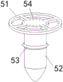
fig. 3 is a schematic view of a structure of a current limiting device.
In the figure, 1, an injector, 2, an extension tube, 3, a main joint, 4, a dropper, 5, a flow limiting device, 6, a second joint, 21, a front section of the extension tube, 22, a rear section of the extension tube, 23, a groove ring, 41, a closing-in, 42, the extension tube, 51, a liquid permeable sheet, 52, a needle plug, 53, a retainer, 54 and a liquid permeable hole are arranged.
Detailed Description
As shown in FIG. 1, an indwelling needle comprising a syringe 1, an extension tube 2, a main adapter 3 and a dropper 4, is characterized in that: the dropper 4 is located in the middle of the extension tube 2, the extension tube 2 is divided into an extension tube front section 21 and an extension tube rear section 22 by the dropper 4, the extension tube front section 21 is connected with the injector 1, the extension tube rear section 22 is connected with the main joint 3, the diameter of the dropper 4 is larger than that of the dropper 4, and the dropper 4 is internally provided with a flow limiting device 5.
As shown in fig. 2, the tube body of the dropper 4 comprises an upper circular truncated cone-shaped closing-in 41 and a lower circular truncated cone-shaped closing-in 41 and a middle telescopic tube 42, the closing-in 41 at the upper part of the dropper 4 is connected with the rear section 22 of the telescopic tube, and the top end of the dropper 4 is provided with a second joint 6 which is also used as a needle plug 52 handle; the bottom end of the dropper 4 is connected with the front section 21 of the extension tube, and the dropper 4 is made of transparent elastic material, so that the condition of the dropper 4 can be observed.
As shown in fig. 3, the flow limiting device 5 comprises a liquid permeable sheet 51 and a needle plug 52, the diameter of the needle plug 52 is equal to the inner diameter of the extension tube 2, the flow limiting effect can be achieved by pushing the needle plug 52 into the extension tube 2, since the dropper 4 is a telescopic tube, the dropper 4 cannot be broken by pushing in and pulling out, and the needle plug 52 can be conveniently aligned with the inner hole position of the extension tube 2; the needle plug 52 is provided with a collar 53, the section of the collar 53 is triangular, the needle plug 52 is connected with the center of the liquid permeable sheet 51, liquid permeable holes 54 are arranged around the liquid permeable sheet 51, and the edge of the liquid permeable sheet 51 is connected with the inner wall of the dropper 4.
As shown in fig. 1 and 3, a groove ring 23 is arranged on the inner side tube wall of the front section 21 of the extension tube, the section of the groove ring 23 is matched with the collar 53, the needle plug 52 is pushed into the extension tube 2, and the collar 53 is clamped into the groove ring 23 to achieve the fixing effect.
When the device is used, before the infusion tube is connected or after the infusion is finished, the tube is sealed, the second connector 6 is held to push the needle plug 52 into the extension tube 2, so that the effect of flow limitation can be achieved, and the extension tube 2 can be kept smooth after being pulled out.
The foregoing description is intended to be illustrative rather than limiting, and it will be appreciated by those skilled in the art that many modifications, variations or equivalents may be made without departing from the spirit and scope of the invention as defined in the appended claims.
Claims (4)
1. An indwelling needle comprising a syringe (1), an extension tube (2), a main joint (3) and a dropper (4), characterized in that: the improved dropper is characterized in that the dropper (4) is located in the middle of the extension pipe (2), the dropper (4) divides the extension pipe (2) into an extension pipe front section (21) and an extension pipe rear section (22), the extension pipe front section (21) is connected with the injector (1), the extension pipe rear section (22) is connected with the main joint (3), the diameter of the dropper (4) is larger than that of the dropper (4), and a flow limiting device (5) is arranged in the dropper (4).
2. The indwelling needle according to claim 1, wherein: the dropper comprises a dropper body (4) and is characterized in that the dropper body comprises an upper circular truncated cone-shaped closing-in portion and a lower circular truncated cone-shaped closing-in portion (41) and a middle telescopic pipe (42), the closing-in portion (41) at the upper portion of the dropper body (4) is connected with a rear section (22) of an extension pipe, a second connector (6) is arranged at the top end of the dropper body (4), the bottom end of the dropper body (4) is connected with a front section (21) of the extension pipe, and the dropper body (4) is made of transparent elastic materials.
3. The indwelling needle according to claim 1, wherein: the flow limiting device (5) comprises a liquid permeable sheet (51) and a needle plug (52), the diameter of the needle plug (52) is equal to the inner diameter of the extension pipe (2), a clamping ring (53) is arranged on the needle plug (52), the cross section of the clamping ring (53) is triangular, the needle plug (52) is connected to the center of the liquid permeable sheet (51), liquid permeable holes (54) are formed in the periphery of the liquid permeable sheet (51), and the edge of the liquid permeable sheet (51) is connected to the inner wall of the dropper (4).
4. The indwelling needle according to claim 1, wherein: the inner side pipe wall of the front section (21) of the extension pipe is provided with a groove ring (23), and the section of the groove ring (23) is matched with the clamping ring (53).
Priority Applications (1)
| Application Number | Priority Date | Filing Date | Title |
|---|---|---|---|
| CN202120625568.8U CN215023979U (en) | 2021-03-29 | 2021-03-29 | Remaining needle |
Applications Claiming Priority (1)
| Application Number | Priority Date | Filing Date | Title |
|---|---|---|---|
| CN202120625568.8U CN215023979U (en) | 2021-03-29 | 2021-03-29 | Remaining needle |
Publications (1)
| Publication Number | Publication Date |
|---|---|
| CN215023979U true CN215023979U (en) | 2021-12-07 |
Family
ID=79151595
Family Applications (1)
| Application Number | Title | Priority Date | Filing Date |
|---|---|---|---|
| CN202120625568.8U Expired - Fee Related CN215023979U (en) | 2021-03-29 | 2021-03-29 | Remaining needle |
Country Status (1)
| Country | Link |
|---|---|
| CN (1) | CN215023979U (en) |
-
2021
- 2021-03-29 CN CN202120625568.8U patent/CN215023979U/en not_active Expired - Fee Related
Similar Documents
| Publication | Publication Date | Title |
|---|---|---|
| CN201939855U (en) | Acupuncture-prevention venous retention needle | |
| CN215023979U (en) | Remaining needle | |
| CN202715086U (en) | Disposable anti-acupuncture intravenous infusion needle | |
| CN204972516U (en) | Novel acupuncture of preventing hinder type and keep somewhere needle | |
| CN113041439B (en) | Closed needleless connection straight type indwelling needle | |
| CN211798019U (en) | Remaining needle | |
| CN210750637U (en) | Safety sheath for intravenous infusion needle | |
| CN203090042U (en) | Catheter connecting device | |
| CN205322983U (en) | Blood is pjncture needle for internal medicine | |
| CN210844671U (en) | Remaining needle convenient for blood sampling and transfusion | |
| CN210409141U (en) | Remaining needle for internal medicine | |
| CN213075660U (en) | Double-joint blood taking needle | |
| CN215275052U (en) | Flaring indwelling needle | |
| CN204411475U (en) | Anti-slip anti-blocking three-channel arterial cannula | |
| CN211357355U (en) | Disposable aseptic guide apparatus suit | |
| CN217409459U (en) | Remaining needle convenient for blood sampling and transfusion | |
| CN217472496U (en) | Indwelling needle | |
| CN203493980U (en) | Disposable outer periphery sleeve infusion device | |
| CN210020643U (en) | Syringe | |
| CN215191619U (en) | Remaining needle convenient for blood sampling | |
| CN219630316U (en) | Remaining needle convenient to fix | |
| CN220513223U (en) | Prevent pressing vein and keep somewhere needle device | |
| CN219646436U (en) | Anti-drop anti-overflow safety syringe | |
| CN211433196U (en) | Disposable medical catheter needle | |
| CN215608322U (en) | Prevent closed vein of jam and keep somewhere needle |
Legal Events
| Date | Code | Title | Description |
|---|---|---|---|
| GR01 | Patent grant | ||
| GR01 | Patent grant | ||
| CF01 | Termination of patent right due to non-payment of annual fee | ||
| CF01 | Termination of patent right due to non-payment of annual fee |
Granted publication date: 20211207 |