CN215009254U - High temperature environment switch board - Google Patents
High temperature environment switch board Download PDFInfo
- Publication number
- CN215009254U CN215009254U CN202121764303.2U CN202121764303U CN215009254U CN 215009254 U CN215009254 U CN 215009254U CN 202121764303 U CN202121764303 U CN 202121764303U CN 215009254 U CN215009254 U CN 215009254U
- Authority
- CN
- China
- Prior art keywords
- cabinet body
- liquid
- fixedly arranged
- pipe
- temperature environment
- Prior art date
- Legal status (The legal status is an assumption and is not a legal conclusion. Google has not performed a legal analysis and makes no representation as to the accuracy of the status listed.)
- Active
Links
Images


Landscapes
- Cooling Or The Like Of Electrical Apparatus (AREA)
Abstract
The utility model discloses a high temperature environment switch board, which comprises a cabinet body, wherein the front side of the cabinet body is provided with a cabinet door, the bottoms of the two sides of the cabinet body are respectively provided with a plurality of radiating grooves, the inner walls of the two sides of the cabinet body are respectively fixedly provided with a cooling pipe, one end of each of the two cooling pipes is fixedly connected through a first connecting pipe, the other end of each of the two cooling pipes is fixedly connected through a second connecting pipe, the back side of the cabinet body is fixedly provided with a liquid storage box, the top end of the liquid storage box is fixedly provided with a liquid inlet pipe, the bottom of the back side of the liquid storage box is fixedly provided with a liquid outlet pipe, one side of the liquid storage box is fixedly provided with a support plate, the top end of the support plate is fixedly provided with a water pump, and the liquid inlet end of the water pump is communicated with the interior of the liquid storage box through a liquid suction pipe; the utility model has the advantages that: the inside coolant liquid suction of the liquid reserve tank inside to two cooling tubes is convenient for through the water pump that sets up to the heat of the internal portion of adsorption cabinet has reduced the internal temperature of cabinet, and the coolant liquid can be discharged into the inside of liquid reserve tank and circulate and use.
Description
Technical Field
The utility model relates to a switch board, in particular to high temperature environment switch board belongs to distribution equipment technical field.
Background
The distribution cabinet (case) is a final-stage device of a distribution system and is a general name of a motor control center. The power distribution cabinet is used in the occasions with dispersed loads and less loops; motor control centers are used in load concentration and loop-rich applications, where they distribute the power from a circuit of a higher level of distribution equipment to nearby loads, which provide protection, monitoring and control of the loads. The cooling and heat dissipation efficiency of the power distribution cabinet used at present is low, when the power distribution cabinet is used in a high-temperature environment, the heat inside the power distribution cabinet cannot be discharged in time, and the service life of components in the power distribution cabinet is shortened.
SUMMERY OF THE UTILITY MODEL
An object of the utility model is to provide a high temperature environment switch board to when the high temperature environment that proposes in solving above-mentioned background art uses, the inside heat of switch board can not in time be discharged, reduces the life's of components and parts problem in the switch board.
In order to achieve the above object, the utility model provides a following technical scheme: a high-temperature environment power distribution cabinet comprises a cabinet body, wherein a cabinet door is arranged on the front side of the cabinet body, a plurality of radiating grooves are formed in the bottoms of two sides of the cabinet body, cooling pipes are fixedly arranged on the inner walls of the two sides of the cabinet body, one ends of the two cooling pipes are fixedly connected through a first connecting pipe, the other ends of the two cooling pipes are fixedly connected through a second connecting pipe, a liquid storage box is fixedly arranged on the back side of the cabinet body, a liquid inlet pipe is fixedly arranged at the top end of the liquid storage box, a liquid outlet pipe is fixedly arranged at the bottom of the back side of the liquid storage box, a supporting plate is fixedly arranged on one side of the liquid storage box, a water pump is fixedly arranged at the top end of the supporting plate, the liquid inlet end of the water pump is communicated with the interior of the liquid storage box through a liquid suction pipe, the liquid outlet end of the water pump is fixedly connected with the middle of the second connecting pipe through a first communicating pipe, one end of the first connecting pipe is communicated with the interior of the liquid storage box through a second communicating pipe, the top of the cabinet body is provided with a heat dissipation assembly.
As a preferred technical scheme of the utility model, radiator unit includes driving motor, connecting axle and fixed plate, driving motor is fixed to be set up the top of the cabinet body one side, the fixed setting of one end of connecting axle is in on driving motor's the transmission shaft, the fixed surface of connecting axle is equipped with the first bevel gear of a plurality of, the fixed plate is fixed to be set up the top of the internal portion of cabinet, the surface of fixed plate is connected with a plurality of axis of rotation, a plurality of through bearing rotation the top of axis of rotation is all fixed be equipped with first bevel gear engaged with second bevel gear, a plurality of the bottom of axis of rotation is all fixed and is equipped with the flabellum.
As an optimal technical scheme of the utility model, two the surface of cooling tube is all fixed and is equipped with the solid fixed ring of a plurality of, a plurality of gu fixed ring all is in through the fixed setting of dead lever the both sides inner wall of the cabinet body.
As the utility model discloses an optimal technical scheme, a plurality of the radiating groove all sets up to the slope form, and the inside of a plurality of radiating groove is all fixed and is equipped with the dust screen.
As an optimized technical scheme of the utility model, the equal threaded connection of tip of feed liquor pipe and the tip of fluid-discharge tube has sealed lid.
As an optimal technical scheme of the utility model, the fixed temperature controller that is equipped with in top of cabinet body one side, temperature controller's test probe is fixed to be set up the inner wall of the cabinet body, water pump and driving motor all pass through temperature controller and power electric connection.
As an optimized technical scheme of the utility model, the fixed heat preservation that is equipped with of inner wall of liquid reserve tank.
Compared with the prior art, the beneficial effects of the utility model are that: the utility model relates to a high temperature environment switch board, the coolant liquid in the liquid reserve tank is convenient for be pumped into the inside of two cooling pipes through the water pump that sets up to adsorb the heat in the internal portion of cabinet, reduced the temperature in the cabinet body, and the coolant liquid can be discharged into the inside of liquid reserve tank and recycled; the driving motor through setting up can drive the connecting axle and rotate, drives a plurality of axis of rotation and rotates simultaneously under the meshing cooperation of first bevel gear and second bevel gear to the flabellum that drives the axis of rotation bottom rotates, can discharge the heat of the internal portion of cabinet through a plurality of radiating groove fast, reduces the temperature of the internal portion of cabinet fast.
Drawings
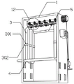
Fig. 1 is a schematic structural view of the present invention;
FIG. 2 is a schematic view of the back structure of the present invention;
fig. 3 is a schematic sectional structure of the present invention;
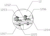
fig. 4 is an enlarged schematic structural view of the heat dissipation assembly of the present invention.
In the figure: 1. a cabinet body; 2. a cabinet door; 3. a cooling tube; 301. a fixing ring; 302. fixing the rod; 4. a first connecting pipe; 5. a second connecting pipe; 6. a liquid storage tank; 601. a liquid inlet pipe; 602. a liquid discharge pipe; 7. a support plate; 8. a water pump; 9. a first communication pipe; 10. a second communicating pipe; 11. a heat sink; 12. a heat dissipating component; 1201. a drive motor; 1202. a connecting shaft; 1203. a first bevel gear; 1204. a fixing plate; 1205. a rotating shaft; 1206. a second bevel gear; 1207. a fan blade; 13. a temperature controller.
Detailed Description
The technical solutions in the embodiments of the present invention will be described clearly and completely with reference to the accompanying drawings in the embodiments of the present invention, and it is obvious that the described embodiments are only some embodiments of the present invention, not all embodiments. Based on the embodiments in the present invention, all other embodiments obtained by a person skilled in the art without creative work belong to the protection scope of the present invention.
Referring to fig. 1-4, the utility model provides a high temperature environment power distribution cabinet, which comprises a cabinet body 1, a cabinet door 2 is arranged on the front side of the cabinet body 1, a plurality of heat dissipation grooves 11 are arranged on the bottom of both sides of the cabinet body 1, cooling pipes 3 are fixedly arranged on the inner walls of both sides of the cabinet body 1, one ends of the two cooling pipes 3 are fixedly connected through a first connecting pipe 4, the other ends of the two cooling pipes 3 are fixedly connected through a second connecting pipe 5, a liquid storage tank 6 is fixedly arranged on the back side of the cabinet body 1, a liquid inlet pipe 601 is fixedly arranged on the top end of the liquid storage tank 6, a liquid outlet pipe 602 is fixedly arranged on the bottom of the back side of the liquid storage tank 6, a support plate 7 is fixedly arranged on one side of the liquid storage tank 6, a water pump 8 is fixedly arranged on the top end of the support plate 7, the liquid inlet end of the water pump 8 is communicated with the interior of the liquid storage tank 6 through a liquid extraction pipe, the liquid outlet end of the water pump 8 is fixedly connected with the middle part of the second connecting pipe 5 through a first connecting pipe 9, the one end of first connecting pipe 4 is linked together through the inside of second communicating pipe 10 with liquid reserve tank 6, and the top of the internal portion of cabinet is equipped with radiator unit 12, can discharge the heat of the internal portion of cabinet 1 through a plurality of radiating groove 11 fast, reduces the temperature of the internal portion of cabinet 1 fast.
Preferably, the heat dissipation assembly 12 includes a driving motor 1201, a connecting shaft 1202 and a fixing plate 1204, the driving motor 1201 is fixedly disposed at the top of one side of the cabinet body 1, one end of the connecting shaft 1202 is fixedly disposed on a transmission shaft of the driving motor 1201, a plurality of first bevel gears 1203 are fixedly disposed on the surface of the connecting shaft 1202, the fixing plate 1204 is fixedly disposed at the top of the inside of the cabinet body 1, a plurality of rotating shafts 1205 are rotatably connected on the surface of the fixing plate 1204 through bearings, second bevel gears 1206 meshed with the first bevel gears 1203 are fixedly disposed at the top ends of the plurality of rotating shafts 1205, fan blades 1207 are fixedly disposed at the bottom ends of the plurality of rotating shafts 1205, the driving motor 1201 drives the connecting shaft 1202 to rotate, the plurality of rotating shafts 1205 are driven to rotate simultaneously under the meshing cooperation of the first bevel gears 1203 and the second bevel gears 1206, and accordingly the fan blades 1207 at the bottom ends of the rotating shafts 1205 are driven to rotate; the surfaces of the two cooling pipes 3 are fixedly provided with a plurality of fixing rings 301, and the fixing rings 301 are fixedly arranged on the inner walls of the two sides of the cabinet body 1 through fixing rods 302, so that the two cooling pipes 3 can be conveniently and fixedly installed; the plurality of radiating grooves 11 are all arranged in an inclined shape, and dustproof nets are fixedly arranged inside the plurality of radiating grooves 11, so that waterproof and dustproof effects are achieved; the end part of the liquid inlet pipe 601 and the end part of the liquid outlet pipe 602 are both in threaded connection with sealing covers, so that the liquid inlet pipe 601 and the liquid outlet pipe 602 can be sealed; a temperature controller 13 is fixedly arranged at the top of one side of the cabinet body 1, a detection probe of the temperature controller 13 is fixedly arranged on the inner wall of the cabinet body 1, the water pump 8 and the driving motor 1201 are both electrically connected with a power supply through the temperature controller 13, and the work of the water pump 8 and the driving motor 1201 can be automatically controlled through the arranged temperature controller 13; the fixed heat preservation that is equipped with of inner wall of liquid reserve tank 6 can play thermal-insulated effect to the inside coolant liquid of liquid reserve tank 6, prevents that high temperature environment from causing the temperature of coolant liquid to rise.
When the high-temperature environment power distribution cabinet is used, the sealing cover of the liquid inlet pipe 601 is opened at first, a certain amount of cooling liquid is added into the liquid storage tank 6, and the sealing cover is closed; then setting the temperature control range of the temperature controller 13, when the components inside the cabinet 1 work, discharging the heat accumulated inside the cabinet 1 through the plurality of heat dissipation grooves 11, when the temperature inside the cabinet 1 continuously rises to reach the temperature control range of the temperature controller 13, the temperature controller 13 controlling the water pump 8 and the driving motor 1201 to work, the water pump 8 working to pump the cooling liquid inside the liquid storage tank 6 into the two cooling pipes 3 to absorb the heat inside the cabinet 1, the absorbed cooling liquid enters the liquid storage tank 6 through the second communication pipe 10 for recycling, the driving motor 1201 driving the connecting shaft 1202 to rotate, the first bevel gear 1203 and the second bevel gear 1206 mesh together to drive the plurality of rotating shafts 1205 to rotate simultaneously, thereby driving the fan blades 1207 at the bottom ends of the rotating shafts 1205 to rotate, and rapidly discharging the heat inside the cabinet 1 through the plurality of heat dissipation grooves 11, the temperature inside the cabinet 1 is rapidly lowered.
Although embodiments of the present invention have been shown and described, it will be appreciated by those skilled in the art that changes, modifications, substitutions and alterations can be made in these embodiments without departing from the principles and spirit of the invention, the scope of which is defined in the appended claims and their equivalents.
Claims (7)
1. The high-temperature environment power distribution cabinet comprises a cabinet body (1) and is characterized in that a cabinet door (2) is arranged on the front side of the cabinet body (1), a plurality of radiating grooves (11) are formed in the bottoms of the two sides of the cabinet body (1), cooling pipes (3) are fixedly arranged on the inner walls of the two sides of the cabinet body (1), one ends of the two cooling pipes (3) are fixedly connected through a first connecting pipe (4), the other ends of the two cooling pipes (3) are fixedly connected through a second connecting pipe (5), a liquid storage tank (6) is fixedly arranged on the back side of the cabinet body (1), a liquid inlet pipe (601) is fixedly arranged at the top end of the liquid storage tank (6), a liquid outlet pipe (602) is fixedly arranged at the bottom of the back side of the liquid storage tank (6), a support plate (7) is fixedly arranged on one side of the liquid storage tank (6), a water pump (8) is fixedly arranged at the top end of the support plate (7), the feed liquor end of water pump (8) is linked together through the inside of liquid suction pipe with liquid reserve tank (6), the play liquid end of water pump (8) is through the middle part fixed connection of first communicating pipe (9) and second connecting pipe (5), the one end of first connecting pipe (4) is linked together through the inside of second communicating pipe (10) and liquid reserve tank (6), the inside top of the cabinet body (1) is equipped with radiator unit (12).
2. The high-temperature environment power distribution cabinet according to claim 1, wherein: the heat dissipation assembly (12) comprises a driving motor (1201), a connecting shaft (1202) and a fixing plate (1204), wherein the driving motor (1201) is fixedly arranged at the top of one side of the cabinet body (1), one end of the connecting shaft (1202) is fixedly arranged on a transmission shaft of the driving motor (1201), a plurality of first bevel gears (1203) are fixedly arranged on the surface of the connecting shaft (1202), the fixing plate (1204) is fixedly arranged at the top of the inside of the cabinet body (1), the surface of the fixing plate (1204) is rotatably connected with a plurality of rotating shafts (1205) through bearings, a plurality of second bevel gears (1206) meshed with the first bevel gears (1203) are fixedly arranged at the top ends of the rotating shafts (1205), and fan blades (1207) are fixedly arranged at the bottom ends of the rotating shafts (1205).
3. The high-temperature environment power distribution cabinet according to claim 1, wherein: two the surface of cooling tube (3) is all fixed and is equipped with the solid fixed ring of a plurality of (301), a plurality of gu fixed ring (301) all are in through fixed pole (302) fixed the setting the both sides inner wall of the cabinet body (1).
4. The high-temperature environment power distribution cabinet according to claim 1, wherein: a plurality of radiating groove (11) all set up to the slope form, and the inside of a plurality of radiating groove (11) all is fixed and is equipped with the dust screen.
5. The high-temperature environment power distribution cabinet according to claim 1, wherein: the end part of the liquid inlet pipe (601) and the end part of the liquid outlet pipe (602) are both in threaded connection with sealing covers.
6. The high-temperature environment power distribution cabinet according to claim 2, wherein: the top of the cabinet body (1) one side is fixedly provided with a temperature controller (13), a detection probe of the temperature controller (13) is fixedly arranged on the inner wall of the cabinet body (1), and the water pump (8) and the driving motor (1201) are both electrically connected with a power supply through the temperature controller (13).
7. The high-temperature environment power distribution cabinet according to claim 1, wherein: and a heat-insulating layer is fixedly arranged on the inner wall of the liquid storage tank (6).
Priority Applications (1)
| Application Number | Priority Date | Filing Date | Title |
|---|---|---|---|
| CN202121764303.2U CN215009254U (en) | 2021-07-30 | 2021-07-30 | High temperature environment switch board |
Applications Claiming Priority (1)
| Application Number | Priority Date | Filing Date | Title |
|---|---|---|---|
| CN202121764303.2U CN215009254U (en) | 2021-07-30 | 2021-07-30 | High temperature environment switch board |
Publications (1)
| Publication Number | Publication Date |
|---|---|
| CN215009254U true CN215009254U (en) | 2021-12-03 |
Family
ID=79125103
Family Applications (1)
| Application Number | Title | Priority Date | Filing Date |
|---|---|---|---|
| CN202121764303.2U Active CN215009254U (en) | 2021-07-30 | 2021-07-30 | High temperature environment switch board |
Country Status (1)
| Country | Link |
|---|---|
| CN (1) | CN215009254U (en) |
-
2021
- 2021-07-30 CN CN202121764303.2U patent/CN215009254U/en active Active
Similar Documents
| Publication | Publication Date | Title |
|---|---|---|
| CN212286242U (en) | Heat radiator in electric welding casing | |
| CN215009254U (en) | High temperature environment switch board | |
| CN116387695B (en) | Combined battery PACK box | |
| CN117767658A (en) | Heat radiation structure for gravity energy storage working motor | |
| CN215927920U (en) | High-efficient heat abstractor that air compressor used | |
| CN213959940U (en) | Wind power converter cooling device | |
| CN214478593U (en) | High-low voltage power distribution cabinet with good heat dissipation effect for building construction | |
| CN216282867U (en) | Effectual glass steel cooling tower of high-efficient cooling | |
| CN213937666U (en) | Mechanical automatic refrigeration heat dissipation motor | |
| CN215725411U (en) | Water circulation system of cooling tower | |
| CN214755694U (en) | Green type photovoltaic solar energy storage device | |
| CN209840749U (en) | Cooling tower structure for fatty acid methyl ester production | |
| CN208461781U (en) | A kind of photovoltaic battery panel cooling device | |
| CN216355641U (en) | Movable transformer substation capable of achieving superconducting cooling | |
| CN220955935U (en) | Engine body cooling device for wind power generation | |
| CN220229624U (en) | Seawater source heat pump system with energy storage device | |
| CN221102213U (en) | Battery radiating tube | |
| CN221042562U (en) | Self-heat-dissipation motor | |
| CN219937156U (en) | Battery cooling device for energy storage | |
| CN221901205U (en) | Outdoor portable power source shell | |
| CN212875111U (en) | Electric power cabinet | |
| CN212211622U (en) | External sealed electrical cabinet | |
| CN221466663U (en) | Lithium iron phosphate battery energy storage power cabinet | |
| CN219536640U (en) | Safety production management device for incremental power distribution network | |
| CN216407101U (en) | Oil circuit circulating type air compressor |
Legal Events
| Date | Code | Title | Description |
|---|---|---|---|
| GR01 | Patent grant | ||
| GR01 | Patent grant | ||
| CP03 | Change of name, title or address | ||
| CP03 | Change of name, title or address |
Address after: 450000 room 625, Shangding building, No. 1356, hanghai East Road, Zhengzhou area (Economic Development Zone), Henan pilot Free Trade Zone, Zhengzhou City, Henan Province Patentee after: Henan Zhikai Intelligent Technology Co.,Ltd. Address before: 450000 room 625, Shangding building, No. 1356, hanghai East Road, economic and Technological Development Zone, Zhengzhou City, Henan Province Patentee before: HENAN ZHIKAI INTELLIGENT TECHNOLOGY Co.,Ltd. |