CN215004416U - Data sampling device for aquatic environment management - Google Patents
Data sampling device for aquatic environment management Download PDFInfo
- Publication number
- CN215004416U CN215004416U CN202023301811.5U CN202023301811U CN215004416U CN 215004416 U CN215004416 U CN 215004416U CN 202023301811 U CN202023301811 U CN 202023301811U CN 215004416 U CN215004416 U CN 215004416U
- Authority
- CN
- China
- Prior art keywords
- buoyancy ball
- ball
- wall
- collecting pipe
- sampling device
- Prior art date
- Legal status (The legal status is an assumption and is not a legal conclusion. Google has not performed a legal analysis and makes no representation as to the accuracy of the status listed.)
- Expired - Fee Related
Links
- 238000005070 sampling Methods 0.000 title claims abstract description 92
- 229920000742 Cotton Polymers 0.000 claims abstract description 63
- 238000001179 sorption measurement Methods 0.000 claims abstract description 24
- 238000007789 sealing Methods 0.000 claims abstract description 15
- 238000010521 absorption reaction Methods 0.000 claims description 30
- 230000000087 stabilizing effect Effects 0.000 claims description 22
- 239000011521 glass Substances 0.000 claims description 3
- 230000002745 absorbent Effects 0.000 claims description 2
- 239000002250 absorbent Substances 0.000 claims description 2
- 238000005067 remediation Methods 0.000 claims 9
- XLYOFNOQVPJJNP-UHFFFAOYSA-N water Substances O XLYOFNOQVPJJNP-UHFFFAOYSA-N 0.000 abstract description 84
- 238000001514 detection method Methods 0.000 abstract description 7
- 230000000149 penetrating effect Effects 0.000 abstract 1
- 230000000694 effects Effects 0.000 description 15
- 239000003381 stabilizer Substances 0.000 description 8
- 230000005484 gravity Effects 0.000 description 5
- 238000010586 diagram Methods 0.000 description 4
- 238000007726 management method Methods 0.000 description 4
- 230000007613 environmental effect Effects 0.000 description 3
- 238000004458 analytical method Methods 0.000 description 1
- 238000013500 data storage Methods 0.000 description 1
- 238000004519 manufacturing process Methods 0.000 description 1
- 238000000034 method Methods 0.000 description 1
- 238000003756 stirring Methods 0.000 description 1
- 238000003911 water pollution Methods 0.000 description 1
Images


Abstract
The utility model provides a data sampling device for aquatic environment management, which comprises an upper buoyancy ball, a sleeve column is fixedly arranged at the top of the upper buoyancy ball, an inserting column is sleeved inside the sleeve column, a sampling collecting pipe is fixedly arranged at the top of the inserting column, collecting drawers are arranged on two sides of the sampling collecting pipe in a penetrating way, a lower buoyancy ball is arranged at the lower end of the inner wall of the upper buoyancy ball in an inserting way, inner adsorption cotton is fixedly arranged at two ends inside the lower buoyancy ball, the inner wall of the lower buoyancy ball at one end corresponding to the inner adsorption cotton is stably adsorbed by a sealing plate, and outer adsorption cotton is fixedly arranged on the inner wall of the lower buoyancy ball at one end corresponding to the sealing plate, the problem that the existing sampling device only floats on the water surface to collect water samples and can not collect water samples at different depth positions of water, so that the sampling device is not comprehensive enough when detecting the water samples is used for detecting the water samples, thereby the data of the water samples at different depths can not be guaranteed to be consistent, the technical problem that the error of water sample data detection is large is easily caused.
Description
Technical Field
The utility model relates to an environmental control technical field on water, more specifically the theory that says so relates to a data sampling device for environmental control on water.
Background
The water pollution management is an important component of environmental management, manages the economic and social activities of people by administrative, economic, technical and legal means according to economic rules and ecological rules, coordinates the relationship between development and environment, and achieves the purposes of developing production and protecting environment.
Based on the above description, and retrieve a utility model patent with application number of CN201921209501.5, it is about a data sampling device for aquatic environment improvement, including the mounting panel, mounting panel lateral wall fixedly connected with rubber air cushion etc. all around, discover through the retrieval mainly through the data sampling special design for aquatic environment improvement, the whole device suspends in the surface of water, is convenient for carry out the purpose of taking a sample and adopt mechanical structure to realize the full automatization work that is used for the data sampling of aquatic environment improvement to the water after sampling and detect and data storage.
After retrieval and analysis, and through long-time research and continuous experimental discovery of an applicant in the field, the sampling device in the patent only floats on the water surface to collect water samples, but cannot collect water samples at different depth positions of water, so that the sampling device is not comprehensive enough when detecting the water sample data, the water sample data at different depths cannot be consistent, the error of water sample data detection is easy to cause large problems, and the like, and therefore, the data sampling device for aquatic environment management needs to be provided again.
SUMMERY OF THE UTILITY MODEL
In order to solve the technical problem, the utility model provides a data sampling device for water environment improvement to solve current sampling device and only float on the surface of water and carry out water sample collection, and can not carry out the water sample collection of the different degree of depth positions department of water, make it comprehensive inadequately when detecting water sample data, thereby can not guarantee the water sample data of the different degree of depth all unanimously, easily cause the big technical problem of error of water sample data detection.
The utility model relates to a data sampling device's purpose for aquatic environment administers is reached by following specific technological means:
the utility model provides a data sampling device for aquatic environment is administered, including last buoyancy ball, the fixed cover post that is provided with in top of last buoyancy ball, and cover post inside cup joints and is provided with the grafting post, the top of grafting post is all fixed and is provided with the sampling collecting pipe, and the both sides of sampling collecting pipe all run through and are provided with the collection steamer tray, the lower extreme grafting of last buoyancy ball inner wall is provided with down the buoyancy ball, and the inside both ends of lower buoyancy ball are all fixed and are provided with the interior absorption cotton, the lower buoyancy ball inner wall of the one end that the interior absorption cotton corresponds each other all adsorbs stably has the closing plate, and the closing plate corresponds the lower buoyancy ball inner wall of one end each other and all fixes and be provided with the outer absorption cotton.
Preferably, the upper floating ball is still including display screen, fixed block, pulling force rope, perforating hole, caulking groove and magnet No. one, and the fixed block that is provided with in middle-end at upper floating ball top, and the fixed pulling force rope that is provided with in top of fixed block to the display screen is all installed at the upper floating ball top at fixed block both ends, and its display screen all is the inside that is located upper floating ball top, installs sealed waterproof transparent glass on the upper floating ball that the display screen upper end corresponds simultaneously.
Preferably, both sides of last buoyancy ball inner wall lower extreme all are provided with the perforating hole, and the middle part of the bottom one side of last buoyancy ball is provided with the caulking groove to the last buoyancy ball inner wall lower extreme department that the caulking groove corresponds all fixedly is provided with a magnet, and the whole bowl form that is of last buoyancy ball, and the hollow setting of bottom of going up the buoyancy ball simultaneously.
Preferably, the sampling collecting pipe is still including placing the district chamber, and the front end of sampling collecting pipe is the round platform form, and the inner wall of sampling collecting pipe both sides all is provided with places the district chamber to it all runs through the joint and is provided with the collection steamer tray to place the district intracavity.
Preferably, collect and enter into after the steamer tray runs through the sampling collecting pipe and place the district intracavity setting, and the outer wall middle-end of collecting the steamer tray all is provided with the handle to the both sides of collecting the steamer tray and running through with the sampling collecting pipe all are provided with sealed the pad, and the top of placing the district chamber simultaneously and collecting the steamer tray is the opening, and the inside of its sampling collecting pipe is hollow setting.
Preferably, the sampling collecting pipe is fixed on the inserting column and then is arranged in a downward inclined mode, the outer wall of the inserting column is provided with threads, and the inner wall of the sleeve column is provided with threads corresponding to the outer wall of the inserting column.
Preferably, the lower buoyant force ball further comprises a through rod, an embedded plate, a second magnet, a bearing plate and a fixing cotton, the through rod is fixedly arranged on two sides of the upper end of the outer wall of the lower buoyant force ball, the embedded plate is fixedly arranged at the middle end of one side of the top of the lower buoyant force ball, and the second magnet is fixedly arranged at the position, corresponding to one end of the embedded plate, of the upper end of the outer wall of the lower buoyant force ball.
Preferably, the bearing plate is fixedly arranged at each of the two ends of the top of the inner wall of the lower buoyant sphere, the inner absorbent cotton is located at the left end of the bearing plate, the outer absorbent cotton is located at the right end of the bearing plate, the fixed cotton is fixedly arranged at the top of the outer absorbent cotton and located at the inner wall of the lower buoyant sphere fixedly, and the inner absorbent cotton and the outer absorbent cotton are both arranged in an arc shape.
Preferably, the closing plate is including stabilizer ball and stabilizer cover, and the closing plate runs through the middle part setting of loading board, is located the internal adsorption cotton simultaneously and adsorbs between the cotton outward, and the closing plate is located the inside one end of buoyancy ball down and sets up to vertical form to the position department of vertical form is all fixed to be provided with stabilizer ball, fixes being provided with stabilizer cover on the lower buoyancy ball inner wall that its stabilizer ball corresponds, and stabilizer ball is the magnet ball simultaneously, and stabilizer cover inner wall is provided with rather than absorbent magnet.
Preferably, the closing plate is whole to be the arc form and to adsorb cotton with outer the arc of adsorbing cotton and correspond, and the through-hole that runs through the pole that sets up at lower buoyancy ball both ends all is to set up with upper buoyancy ball both sides inner wall corresponds to No. two magnets that lower buoyancy ball outer wall set up correspond with a magnet absorption that upper buoyancy ball inner wall set up, and the buoyancy ball is whole to be the setting of no headspace core down simultaneously, and its lower panel that buoyancy ball top set up corresponds with the caulking groove that upper buoyancy ball bottom set up.
Has the advantages that:
1. the utility model discloses an put into aquatic after stabilizing with last buoyancy ball and lower buoyancy ball combination, can hold the pulling force rope after putting into the aquatic and fix its pulling force rope and bank, be convenient for go up the searching of buoyancy ball and lower buoyancy ball, make it float in the surface of water under the combined action of last buoyancy ball and lower buoyancy ball, alright press buoyancy ball down under the gravity of sampling collecting pipe this moment, make it float down the buoyancy ball submerge completely and the buoyancy ball is located the surface of water, alright get into water gradually in the gap between last buoyancy ball and lower buoyancy ball and be located buoyancy ball and lower buoyancy ball inside, reach and go up the buoyancy ball and sink the effect of sampling collecting pipe sampling collection water in submerging gradually with lower buoyancy ball.
2. Still through treating it buoyancy ball and buoyancy ball all immerse in the aquatic time down, sampling collecting pipe this moment also all immerses in the water, alright enter into the collection steamer tray of both sides when water enters into sampling collecting pipe gradually in, can make its water that enters into in the collection steamer tray can not flow down in the slope of sampling collecting pipe simultaneously, thereby reach the effect that the water was collected in the sampling, and reach the unified collection that the sampling collecting pipe carried out many places water at the in-process that last buoyancy ball removed in aqueous with lower buoyancy ball, it is more stable when being convenient for data detection, avoid only the collection that a single water that carries out to detect.
3. And then, when water enters from the gap between the upper buoyancy ball and the lower buoyancy ball, the water is adsorbed by the outer adsorption cotton to increase the gravity of the lower buoyancy ball, the lower buoyancy ball can drive the upper buoyancy ball and the sampling collecting pipe to enter the water with different depths, and the sampling collecting pipe is used for sampling and collecting water with different depths to check, so that more specific and comprehensive data are achieved.
4. Secondly, when the water in deeper position needs to be sampled and collected, the lower buoyancy ball is broken off before the upper buoyancy ball and the lower buoyancy ball are placed in combination, the panel of the lower buoyancy ball is separated from the caulking groove of the upper buoyancy ball, the lower buoyancy ball is turned inside the upper buoyancy ball under the rotation of the through rod, the lower buoyancy ball is driven to enter the upper buoyancy ball, the second magnet is contacted and adsorbed with the first magnet, and the effect that the lower buoyancy ball is stabilized inside the upper buoyancy ball is achieved, then the sealing plate can be pulled out from the lower end, so that the stabilizing ball at the top of the sealing plate is separated from the stabilizing cover, the sealing plate can be pulled out, at the moment, the upper buoyant force ball and the lower buoyant force ball are put into water, the water is directly contacted with the inner adsorption cotton and the outer adsorption cotton for adsorption, so that the inner adsorption cotton and the outer adsorption cotton are promoted to increase the weight, and the upper buoyancy ball and the lower buoyancy ball can drive the sampling and collecting pipe to sink quickly, thereby achieving the effect of sampling and collecting deep water.
Drawings
In order to more clearly illustrate the technical solutions of the embodiments of the present invention, the drawings that are required to be used in the embodiments will be briefly described below, it should be understood that the following drawings only illustrate some embodiments of the present invention, and therefore should not be considered as limiting the scope, and for those skilled in the art, other related drawings can be obtained according to the drawings without inventive efforts.
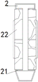
Fig. 1 is the three-dimensional structure diagram of the data sampling device of the present invention.
Fig. 2 is the schematic diagram of the internal three-dimensional structure of the upper floating ball of the present invention.
Fig. 3 is a schematic view of the bottom three-dimensional structure of the lower buoyant force ball of the present invention.
Fig. 4 is the structure schematic diagram of the internal adsorption cotton of the lower buoyancy ball of the utility model.
Fig. 5 is a schematic view of the internal structure of the sampling and collecting tube of the present invention.
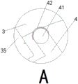
Fig. 6 is an enlarged schematic structural diagram of a in fig. 4 according to the present invention.
In fig. 1 to 6, the correspondence between the component names and the reference numbers is: the device comprises an upper buoyancy ball-1, a display screen-11, a fixed block-12, a tension rope-13, a through hole-14, a caulking groove-15, a first magnet-16, a sleeve column-17, a splicing column-18, a sampling collecting pipe-2, a placing area cavity-21, a collecting drawer-22, a lower buoyancy ball-3, a through rod-31, an embedded plate-32, a second magnet-33, a bearing plate-34, inner adsorption cotton-35, outer adsorption cotton-36, fixed cotton-37, a sealing plate-4, a stabilizing ball-41 and a stabilizing cover-42.
Detailed Description
The technical solutions in the embodiments of the present invention will be described clearly and completely with reference to the accompanying drawings in the embodiments of the present invention, and it is obvious that the described embodiments are only some embodiments of the present invention, not all embodiments. Based on the embodiments in the present invention, all other embodiments obtained by a person skilled in the art without creative work belong to the protection scope of the present invention.
Example (b):
as shown in figures 1 to 6: the utility model provides a data sampling device for aquatic environment is administered, including last buoyancy ball 1, the fixed cover post 17 that is provided with in top of last buoyancy ball 1, and cover post 17 inside cup joints and is provided with grafting post 18, the top of grafting post 18 is all fixed and is provided with sampling collecting pipe 2, and sampling collecting pipe 2's both sides all run through and are provided with collection steamer tray 22, the lower extreme grafting of 1 inner wall of upper buoyancy ball is provided with buoyancy ball 3 down, and the inside both ends of lower buoyancy ball 3 are all fixed and are provided with interior absorption cotton 35, the lower buoyancy ball 3 inner walls of the one end that interior absorption cotton 35 corresponds each other all adsorb stably there is closing plate 4, and closing plate 4 corresponds 3 inner walls of lower buoyancy ball of one end each other and all fixedly is provided with outer absorption cotton 36.
Wherein, upward buoyancy ball 1 is still including display screen 11, fixed block 12, pulling force rope 13, perforating hole 14, caulking groove 15 and magnet 16 No. one, the fixed block 12 that is provided with in middle-end at upward buoyancy ball 1 top, and the fixed pulling force rope 13 that is provided with in top of fixed block 12, and display screen 11 is all installed at upward buoyancy ball 1 top at fixed block 12 both ends, its display screen 11 all is the inside that is located upward buoyancy ball 1 top, install sealed waterproof transparent glass on the upward buoyancy ball 1 that the 11 upper ends of display screen correspond simultaneously, display screen 11 set up can detect the detection data that upward buoyancy ball 1 and lower buoyancy ball 3 reached water depth position department water when making its inside not intake, make it can sample the collection intraductal water detection data who collects and compare, reach more accurate water sample data.
Wherein, the both sides of 1 inner wall lower extreme of upper buoyancy ball all are provided with perforating hole 14, and the middle part of the bottom one side of upper buoyancy ball 1 is provided with caulking groove 15, and 1 inner wall lower extreme department of upper buoyancy ball that caulking groove 15 corresponds all fixedly is provided with magnet 16 No. one, and it is whole that buoyancy ball 1 is the bowl form on it, and upper buoyancy ball 1 is the hollow setting of no end simultaneously, and the setting of upper buoyancy ball 1 shape makes its better float on water, and the stirring of buoyancy ball under the better confession simultaneously.
Wherein, sampling collecting pipe 2 is still including placing district chamber 21, sampling collecting pipe 2's front end is the round platform form, and sampling collecting pipe 2 both sides inner wall all is provided with places district chamber 21, and it is provided with collection steamer tray 22 all to run through the joint in the district chamber 21 to place, the inside setting up of sampling collecting pipe makes its water of collecting live after entering into sampling collecting pipe 2 and enters into in the collection steamer tray 22, make it make under the setting up of sampling collecting pipe 2 slope make enter into the water of collecting in the steamer tray 22 take buoyancy ball 1 with the effect that the inside water can not lose when buoyancy ball 3 down.
Wherein, it sets up to enter into after collecting steamer tray 22 runs through sampling collecting pipe 2 and places the district chamber 21, and the outer wall middle-end of collecting steamer tray 22 all is provided with the handle, and the both sides of collecting steamer tray 22 and sampling collecting pipe 2 through all are provided with sealed the pad, the top of placing district chamber 21 simultaneously and collecting steamer tray 22 is the opening, its sampling collecting pipe 2's inside is hollow setting, the leakproofness is good when collecting steamer tray 22 and placing setting up of district chamber 21 and making it collect steamer tray 22 and be located and place district chamber 21, good stability.
Wherein, sampling collecting pipe 2 all down inclines to set up after fixing on grafting post 18, and the outer wall of grafting post 18 all is provided with the screw thread to the inner wall of cover post 17 all is provided with the screw thread that 18 outer walls of grafting post correspond each other, makes its grafting post 18 can carry out the regulation of different length under the screw thread correspondence of grafting post 18 and cover post, thereby reaches the regulation effect that grafting post 18 drove sampling collecting pipe 2 and carry out different height and the different inclination of sampling collecting pipe 2.
Wherein, lower buoyancy ball 3 is still including lining up pole 31, panel 32, No. two magnet 33, loading board 34 and fixed cotton 37, and the both sides of 3 outer walls upper ends of lower buoyancy ball are all fixed to be provided with and are passed through pole 31, and the middle-end of 3 top one sides of lower buoyancy ball is fixed to be provided with panel 32, and panel 32 corresponds the fixed No. two magnet 33 that is provided with in the upper end position department of 3 outer walls of lower buoyancy ball of one end, and the setting up of the structure of lower buoyancy ball 3 makes its better effect of floating in the surface of water and submerging under carrying out the combination with upper buoyancy ball 1.
Wherein, the both ends at 3 inner wall tops of lower buoyancy ball are all fixed and are provided with loading board 34, and interior absorption cotton 35 is located the left end of loading board 34, outer absorption cotton 36 is located the right-hand member of loading board 34, and outer absorption cotton 36's top is fixed to be provided with fixed cotton 37 and is located 3 inner walls of lower buoyancy ball fixed, it is that it is the arc form setting with outer absorption cotton 35, interior absorption cotton makes it after with water contact with outer absorption cotton's setting, thereby reach the increase of interior absorption cotton 35 and outer absorption cotton 36 weight and can drive buoyancy ball 1 and lower buoyancy ball 3 and sink into the water fast and carry out the collection sampling of different degree of depth water down, thereby reach the effect that the water collection of the different degree of depth detected.
Wherein, the closing plate 4 is including stabilizing ball 41 and stabilizing cover 42, the middle part setting that the closing plate 4 runs through the loading board 34, be located between interior absorption cotton 35 and the outer absorption cotton 36 simultaneously, and the closing plate 4 is located the inside one end of buoyancy ball 3 down and sets up to vertical form, and the position department of vertical form all fixedly is provided with stabilizing ball 41, it is fixed on the lower buoyancy ball 3 inner wall that its stabilizing ball 41 corresponds and is provided with stabilizing cover 42, stabilizing ball 41 is the magnet ball simultaneously, stabilizing cover 42 inner wall is provided with rather than the magnet of absorption, the setting of closing plate 4 makes it can carry out the sheltering from of interior absorption cotton 35 sealed, make it just not contact with water when need not contacting with water, can make its interior absorption cotton 35 and water contact thereby reach the effect that buoyancy ball 3 gravity increases down after pulling out closing plate 4 simultaneously.
Wherein, the whole arc that is the arc form of closing plate 4 corresponds with the arc of interior absorption cotton 35 and outer absorption cotton 36, and the through-hole 14 that the through-hole 31 that sets up with the inner wall setting of 1 both sides of buoyant sphere of lower buoyant sphere 3 both ends set up corresponds, and No. two magnet 33 that the outer wall of buoyant sphere 3 set up down adsorbs with No. one magnet 16 that the inner wall of buoyant sphere 1 set up and corresponds, the whole no top hollow setting that is of buoyant sphere 3 down simultaneously, panel 32 that its 3 tops of buoyant sphere set up corresponds with caulking groove 15 that the upper buoyant sphere 1 bottom set up, through-hole 14 makes its buoyant sphere 3 down more convenient when rotating with the setting up of through-hole 31, and it is more stable when entering into the interior of buoyant sphere 1 that the setting up of magnet 16 and No. two magnet 33 makes its buoyant sphere 3 down.
The working principle is as follows: firstly, the upper buoyancy ball 1 and the lower buoyancy ball 3 are combined and stabilized and then placed into water, the pull rope 13 can be pulled to fix the pull rope 13 with the shore after the combination is placed into the water, so that the upper buoyancy ball 1 and the lower buoyancy ball 3 can be conveniently found, the upper buoyancy ball 1 and the lower buoyancy ball 3 can float on the water surface under the combined action of the upper buoyancy ball 1 and the lower buoyancy ball 3, at the moment, the lower buoyancy ball 3 can be pressed under the gravity of the sampling collecting pipe 2, the lower buoyancy ball 3 can be completely submerged into the water, the upper buoyancy ball 1 is positioned on the water surface, the sampling collecting pipe 2 can carry out sampling collection of water when the upper buoyancy ball 1 and the lower buoyancy ball 3 are both submerged into the water, the sampling collecting pipe 2 is submerged into the water at the moment, and the water can enter the collecting drawers 22 at two sides of the sampling collecting pipe 2 when the water gradually enters the sampling collecting pipe 2, meanwhile, water entering the collecting drawer 22 can not flow out under the inclination of the sampling collecting pipe 2, so that the effect of sampling and collecting 2 water is achieved, and when the upper buoyancy ball 1 and the lower buoyancy ball 3 move in water, the sampling collecting pipe 2 is used for uniformly collecting a plurality of water positions, so that the outer adsorption cotton 36 adsorbs water when water enters from a gap between the upper buoyancy ball 1 and the lower buoyancy ball 3, and the gravity of the lower buoyancy ball 3 is increased, the lower buoyancy ball 3 can drive the upper buoyancy ball 1 and the sampling collecting pipe 2 to enter water with different depths, the water sampled and collected by the sampling collecting pipe 2 is inspected at different depths, more specific and comprehensive data is achieved, and the detection data of the water at the positions where the upper buoyancy ball 1 and the lower buoyancy ball 3 reach can be detected while the water does not enter the display screen 11, when deeper water is required to be sampled and collected, the lower buoyant ball 3 is broken off to separate the panel from the caulking groove 15 of the upper buoyant ball 1 before the combined upper buoyant ball 1 and the lower buoyant ball 3 are placed, so that the lower buoyant ball 3 is turned over in the upper buoyant ball 1 under the rotation of the through rod 31, the lower buoyant ball 3 is promoted to enter the upper buoyant ball 1, the second magnet 33 is contacted and adsorbed with the first magnet 16 at the moment, the effect that the lower buoyant ball 3 is stabilized in the upper buoyant ball 1 is achieved, then the sealing plate 4 can be pulled out downwards from the middle part of the bearing plate 34 at the bottom of the lower buoyant ball 3, and the stabilizing ball 41 at the top of the sealing plate 4 is extruded and moved with the inner absorbing cotton 35 and the outer absorbing cotton 36 and then is suspended at the upper end of the bearing plate 34 after being separated from the stabilizing cover 42, just reach the effect of pulling out sealing plate 4, can up promote sealing plate 4 when closing sealing plate 4 and make its stabilizer ball 41 enter into and carry out corresponding absorption stability in stabilizing the cover 42 can, put into aquatic with buoyancy ball 1 and lower buoyancy ball 3 again after opening sealing plate 4, make its water direct and interior absorption cotton 35 and outer absorption cotton 36 contact absorption, impel interior absorption cotton 35 and outer absorption cotton to increase weight, alright make its buoyancy ball 1 and lower buoyancy ball 3 drive the effect that sampling collecting pipe 2 sinks fast, thereby reach the effect that the sampling collected deep water.
Claims (10)
1. The utility model provides a data sampling device for aquatic environment administers, includes buoyancy ball (1), its characterized in that: go up the fixed cover post (17) that is provided with in top of buoyancy ball (1), and cover post (17) inside cup joints and is provided with grafting post (18), the top of grafting post (18) is all fixed and is provided with sampling collecting pipe (2), and the both sides of sampling collecting pipe (2) all run through and be provided with collection steamer tray (22), the lower extreme grafting of going up buoyancy ball (1) inner wall is provided with buoyancy ball (3) down, and the inside both ends of buoyancy ball (3) all fixed internal adsorption cotton (35) that are provided with down, lower buoyancy ball (3) inner wall of the one end that internal adsorption cotton (35) correspond each other all adsorbs stably has closing plate (4), and closing plate (4) lower buoyancy ball (3) inner wall of the one end that corresponds each other all fixedly is provided with outer adsorption cotton (36).
2. The data sampling device for aquatic environment remediation of claim 1, wherein: go up buoyancy ball (1) still including display screen (11), fixed block (12), pulling force rope (13), perforating hole (14), caulking groove (15) and magnet (16), the fixed block (12) that is provided with in middle-end at last buoyancy ball (1) top, and the fixed pulling force rope (13) that is provided with in top of fixed block (12) to display screen (11) are all installed at the upward buoyancy ball (1) top at fixed block (12) both ends, and its display screen (11) all are the inside that is located buoyancy ball (1) top, install sealed waterproof clear glass on upward buoyancy ball (1) that simultaneous display screen (11) upper end corresponds.
3. The data sampling device for aquatic environment remediation of claim 2, wherein: go up the both sides of buoyancy ball (1) inner wall lower extreme and all be provided with perforating hole (14), and the middle part of the bottom one side of going up buoyancy ball (1) is provided with caulking groove (15) to the last buoyancy ball (1) inner wall lower extreme department that caulking groove (15) correspond all fixedly is provided with magnet (16) No. one, and buoyancy ball (1) wholly is the bowl form on it, goes up buoyancy ball (1) simultaneously and sets up for having no end hollow.
4. The data sampling device for aquatic environment remediation of claim 1, wherein: sampling collecting pipe (2) are still including placing district chamber (21), the front end of sampling collecting pipe (2) is the round platform form, and sampling collecting pipe (2) both sides inner wall all is provided with places district chamber (21) to it is provided with collection steamer tray (22) all to run through the joint in district chamber (21) to place.
5. The data sampling device for aquatic environment remediation of claim 4, wherein: collect steamer tray (22) and run through and enter into behind sampling collecting pipe (2) and place district chamber (21) and set up, and the outer wall middle-end of collecting steamer tray (22) all is provided with the handle to the both sides of collecting steamer tray (22) and sampling collecting pipe (2) through all are provided with sealed the pad, and the top of placing district chamber (21) simultaneously and collecting steamer tray (22) is the opening, and the inside of its sampling collecting pipe (2) is hollow setting.
6. The data sampling device for aquatic environment remediation of claim 4, wherein: the sampling and collecting pipe (2) is fixed on the inserting column (18) and then is arranged obliquely downwards, the outer wall of the inserting column (18) is provided with threads, and the inner wall of the sleeve column (17) is provided with threads corresponding to the outer wall of the inserting column (18).
7. The data sampling device for aquatic environment remediation of claim 1, wherein: the lower buoyancy ball (3) further comprises a through rod (31), an embedded plate (32), a second magnet (33), a bearing plate (34) and fixed cotton (37), the through rod (31) is fixedly arranged on two sides of the upper end of the outer wall of the lower buoyancy ball (3), the embedded plate (32) is fixedly arranged at the middle end of one side of the top of the lower buoyancy ball (3), and the second magnet (33) is fixedly arranged at the position, corresponding to one end, of the upper end of the outer wall of the lower buoyancy ball (3) of the embedded plate (32).
8. The data sampling device for aquatic environment remediation of claim 7, wherein: the two ends of the top of the inner wall of the lower buoyancy ball (3) are fixedly provided with bearing plates (34), inner adsorption cotton (35) is located at the left end of the bearing plates (34), outer adsorption cotton (36) is located at the right end of the bearing plates (34), fixed cotton (37) is arranged at the top of the outer adsorption cotton (36) and located on the inner wall of the lower buoyancy ball (3) and fixed, and the inner adsorption cotton (35) and the outer adsorption cotton (36) are arranged in an arc shape.
9. The data sampling device for aquatic environment remediation of claim 1, wherein: the sealing plate (4) is including stabilizing ball (41) and stabilizing cover (42), the middle part setting that the loading board (34) was run through in sealing plate (4), be located between internal adsorption cotton (35) and the outer adsorption cotton (36) simultaneously, and the sealing plate (4) is located the inside one end of buoyancy ball (3) down and sets up to vertical form to the position department of vertical form all fixes and is provided with stabilizing ball (41), and the lower buoyancy ball (3) inner wall that its stabilizing ball (41) correspond is fixed and is provided with stabilizing cover (42), and stabilizing ball is the magnet ball simultaneously, and stabilizing cover (42) inner wall is provided with rather than absorbent magnet.
10. The data sampling device for aquatic environment remediation of claim 9, wherein: the whole arc that is arc form and interior absorption cotton (35) and outer absorption cotton (36) of closing plate (4) corresponds, and the perforating rod (31) that sets up in buoyancy ball (3) both ends down all are the perforating hole (14) that set up with upward buoyancy ball (1) both sides inner wall and correspond, and No. two magnet (33) that buoyancy ball (3) outer wall set up down adsorb with magnet (16) that upward buoyancy ball (1) inner wall set up and correspond, and buoyancy ball (3) wholly sets up for no headspace core down simultaneously, and panel (32) that its lower buoyancy ball (3) top set up correspond with caulking groove (15) that upward buoyancy ball (1) bottom set up.
Priority Applications (1)
| Application Number | Priority Date | Filing Date | Title |
|---|---|---|---|
| CN202023301811.5U CN215004416U (en) | 2020-12-31 | 2020-12-31 | Data sampling device for aquatic environment management |
Applications Claiming Priority (1)
| Application Number | Priority Date | Filing Date | Title |
|---|---|---|---|
| CN202023301811.5U CN215004416U (en) | 2020-12-31 | 2020-12-31 | Data sampling device for aquatic environment management |
Publications (1)
| Publication Number | Publication Date |
|---|---|
| CN215004416U true CN215004416U (en) | 2021-12-03 |
Family
ID=79142326
Family Applications (1)
| Application Number | Title | Priority Date | Filing Date |
|---|---|---|---|
| CN202023301811.5U Expired - Fee Related CN215004416U (en) | 2020-12-31 | 2020-12-31 | Data sampling device for aquatic environment management |
Country Status (1)
| Country | Link |
|---|---|
| CN (1) | CN215004416U (en) |
Cited By (1)
| Publication number | Priority date | Publication date | Assignee | Title |
|---|---|---|---|---|
| CN114946456A (en) * | 2022-06-17 | 2022-08-30 | 贺跃军 | Agricultural composite buoyancy ball planting mold |
-
2020
- 2020-12-31 CN CN202023301811.5U patent/CN215004416U/en not_active Expired - Fee Related
Cited By (1)
| Publication number | Priority date | Publication date | Assignee | Title |
|---|---|---|---|---|
| CN114946456A (en) * | 2022-06-17 | 2022-08-30 | 贺跃军 | Agricultural composite buoyancy ball planting mold |
Similar Documents
| Publication | Publication Date | Title |
|---|---|---|
| CN215004416U (en) | Data sampling device for aquatic environment management | |
| CN207846381U (en) | A kind of blocking apparatus of cleaning floater | |
| CN115326490A (en) | Surface water sampling device for environmental monitoring | |
| CN113176389A (en) | Water source detection device convenient to detect different degree of depth water sources | |
| CN114323810A (en) | Hydrogeology is with water level observation device | |
| CN201628679U (en) | Water quality monitor | |
| CN206339533U (en) | A kind of liquid level volatilization gas automatic detecting structure | |
| CN209281706U (en) | A kind of portable physics teaching laboratory apparatus | |
| CN208125461U (en) | A kind of static chamber for the acquisition of strand intertidal zone wetland greenhouse gases | |
| CN212988939U (en) | Contact type gas collecting device with superficial sediment | |
| CN114459824A (en) | Regional water quality sampler for environmental quality detection and detection method | |
| CN214658967U (en) | Building engineering measures pay-off | |
| CN210269303U (en) | Groundwater sample thief for hydrogeology | |
| CN213466910U (en) | Water sampling and filtering device | |
| CN212621667U (en) | Novel water quality detection device | |
| CN213632786U (en) | Deep sampling device of water quality monitoring | |
| CN116429498A (en) | River sewage sampling device | |
| CN112012184A (en) | Floating platform for automatically collecting leaked crude oil at sea | |
| CN213274969U (en) | Hydrology surveys depthkeeping water intaking ware | |
| CN216050885U (en) | Water environment monitoring sampling device convenient to carry | |
| CN215677707U (en) | Portable environmental science water sample collection system | |
| CN220772632U (en) | Sampling device for water quality detection | |
| CN213121218U (en) | Water quality testing water intake device | |
| CN109374357A (en) | A kind of sample collecting device for marine pollutant | |
| CN115060863B (en) | Water quality detection device |
Legal Events
| Date | Code | Title | Description |
|---|---|---|---|
| GR01 | Patent grant | ||
| GR01 | Patent grant | ||
| CF01 | Termination of patent right due to non-payment of annual fee |
Granted publication date: 20211203 |
|
| CF01 | Termination of patent right due to non-payment of annual fee |