CN215004402U - Soil pollution sampling device - Google Patents
Soil pollution sampling device Download PDFInfo
- Publication number
- CN215004402U CN215004402U CN202121402047.2U CN202121402047U CN215004402U CN 215004402 U CN215004402 U CN 215004402U CN 202121402047 U CN202121402047 U CN 202121402047U CN 215004402 U CN215004402 U CN 215004402U
- Authority
- CN
- China
- Prior art keywords
- cylinder
- lifting seat
- shell
- piston
- connecting rod
- Prior art date
- Legal status (The legal status is an assumption and is not a legal conclusion. Google has not performed a legal analysis and makes no representation as to the accuracy of the status listed.)
- Active
Links
Images


Landscapes
- Sampling And Sample Adjustment (AREA)
Abstract
The utility model relates to a soil pollution sampling device, which comprises a shell and a lifting seat, wherein the lifting seat is slidably arranged in the shell, a motor with double output shafts is arranged on the top side of the lifting seat, and the output end of the bottom of the motor with double output shafts runs through the lifting seat and is provided with a rotating shaft; when the lifting seat moves down, the first connecting rod is driven to move down at the moment, so that the first piston moves down in the first cylinder, air in the second cylinder is sucked into the first cylinder, the second piston is driven to drive the second connecting rod to move, the two push plates are kept away from each other, soil sampled at the moment is accumulated between the two push plates, when the lifting seat is completely sampled and returns to the original position, the first connecting rod moves up at the moment, the first piston rises in the first cylinder, air in the second cylinder is pressed into the first cylinder, the second piston is driven to drive the second connecting rod to move, the two push plates are close to each other, the soil is pushed into the sampling pit hole, automatic backfilling is achieved, and practical use and operation are facilitated.
Description
Technical Field
The utility model relates to a soil pollution sampling device technical field especially relates to a soil pollution sampling device.
Background
The detection of soil pollutants is the important field of environmental detection, and when soil pollutants are detected, the soil at different depths is collected through a soil pollution sampling device.
The downward movement and the rotation of a screw shaft of the existing soil pollution sampling device are respectively completed by different power devices, and the screw shaft is inconvenient to recover; meanwhile, after sampling is completed, the automatic soil filling function cannot be realized according to the self work of the device, and subsequent soil filling operation is required manually.
SUMMERY OF THE UTILITY MODEL
The utility model solves the problems that the downward movement and the rotation of the screw shaft of the existing soil pollution sampling device are respectively completed by different power devices, and the screw shaft is not convenient to recover; meanwhile, after sampling is completed, the automatic soil filling function cannot be realized according to the self work of the device, and the subsequent soil filling operation needs to be carried out manually.
In order to achieve the above purpose, the utility model adopts the following technical scheme:
a soil pollution sampling device comprises a shell and a lifting seat, wherein the lifting seat is slidably mounted in the shell, a double-output-shaft motor is mounted on the top side of the lifting seat, the output end of the bottom of the double-output-shaft motor penetrates through the lifting seat to be mounted with a rotating shaft, a helical blade is arranged on the outer side of the rotating shaft, a threaded rod is mounted at the output end of the top of the double-output-shaft motor, and the threaded rod penetrates through the top wall of the shell;
first barrel is installed to casing top symmetry, first barrel internally mounted has first piston, first piston is connected with head rod one end, and the head rod other end is connected with dual output shaft motor, a plurality of support arm is installed to the casing bottom, and the support arm is connected with the rectangle frame, the second barrel is all installed to the outside two opposite sides of rectangle frame, second barrel internally mounted has the second piston, the second piston is connected with second connecting rod one end, the second connecting rod other end runs through the rectangle frame and installs the push pedal, first barrel and second barrel pass through connecting pipe turn-on connection.
Preferably, the handles are symmetrically installed on the outer side of the shell, the threaded sleeve is installed on the top of the shell in a penetrating mode, and the threaded sleeve is in threaded connection with the threaded rod.
Preferably, guide rods are symmetrically arranged on the top side of the double-output-shaft motor and penetrate through the top wall of the shell.
Preferably, the push plate is semicircular in shape, and the inner diameter of the push plate is the same as the outer diameter of the helical blade.
Preferably, the top end of the first cylinder and the end, far away from the push plate, of the second cylinder are in conduction connection through a connecting pipe.
The utility model has the advantages that: the motor with double output shafts works to drive the rotating shaft and the helical blade to rotate, meanwhile, the threaded rod is driven to rotate, the lifting seat is matched with the threaded sleeve in threaded connection to lift in the shell, the functions of downward movement and rotation are completed through the motor with double output shafts, and the structure is greatly optimized;
when the lifting seat moves down, the first connecting rod is driven to move down at the moment, so that the first piston moves down in the first cylinder, air in the second cylinder is sucked into the first cylinder, the second piston is driven to drive the second connecting rod to move, the two push plates are kept away from each other, soil sampled at the moment is accumulated between the two push plates, when the lifting seat is completely sampled and returns to the original position, the first connecting rod moves up at the moment, the first piston rises in the first cylinder, air in the second cylinder is pressed into the first cylinder, the second piston is driven to drive the second connecting rod to move, the two push plates are close to each other, the soil is pushed into the sampling pit hole, automatic backfilling is achieved, and practical use and operation are facilitated.
Drawings
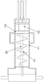
FIG. 1 is a schematic view of the overall structure of the present invention;
FIG. 2 is an overall sectional view of the present invention;
fig. 3 is a schematic view of the connection structure of the first cylinder and the second cylinder of the present invention.
Illustration of the drawings:
1. a housing; 2. a lifting seat; 3. a motor with double output shafts; 4. a threaded rod; 5. a guide bar; 6. a rotating shaft; 7. a helical blade; 8. a first cylinder; 9. a first piston; 10. a first connecting rod; 11. a support arm; 12. a rectangular frame; 13. a second cylinder; 14. a second piston; 15. a second connecting rod; 16. pushing the plate; 17. a connecting pipe; 18. and (4) a threaded sleeve.
Detailed Description
The technical solutions in the embodiments of the present invention will be described clearly and completely with reference to the accompanying drawings in the embodiments of the present invention, and it is obvious that the described embodiments are only some embodiments of the present invention, not all embodiments. Based on the embodiments of the present invention, all other embodiments obtained by a person of ordinary skill in the art without creative efforts belong to the protection scope of the present invention.
Specific examples are given below.
Referring to fig. 1-3, a soil pollution sampling device comprises a shell 1 and a lifting seat 2, wherein the lifting seat 2 is slidably mounted in the shell 1, a double-output-shaft motor 3 is mounted on the top side of the lifting seat 2, the output end of the bottom of the double-output-shaft motor 3 penetrates through the lifting seat 2 and is provided with a rotating shaft 6, a helical blade 7 is arranged on the outer side of the rotating shaft 6, a threaded rod 4 is mounted on the output end of the top of the double-output-shaft motor 3, and the threaded rod 4 penetrates through the top wall of the shell 1;
As an embodiment of the utility model, the handle is installed to 1 outside symmetry of casing, be convenient for carry the device, 1 top of casing is run through and is installed thread bush 18, and thread bush 18 and 4 threaded connection of threaded rod, guide arm 5 is installed to 3 top side symmetries of dual output shaft motor, guide arm 5 runs through 1 roof of casing, it is rotatory that 3 works of dual output shaft motor drive pivot 6 and helical blade 7, it is rotatory to drive threaded rod 4 simultaneously, 18 cooperations of thread bush with threaded connection realize the lift of seat 2 in casing 1, and play the guide effect through guide arm 5.
As an embodiment of the utility model, the shape of push pedal 16 is semi-circular, and the internal diameter of push pedal 16 is the same with helical blade 7's external diameter, and the sampling hole size adaptation that the push pedal 16 of being convenient for and helical blade 7 dug out is backfilled earth to the sampling hole in through push pedal 16.
As an embodiment of the utility model, 8 tops of first barrel and second barrel 13 are kept away from 16 ends of push pedal and are passed through connecting pipe 17 turn-on connection, guarantee the inside circulation of air of first barrel 8 and second barrel 13, realize that first barrel 8 and the inside pressure of second barrel 13 are unanimous.
The working principle is as follows: the device is placed on a sampling point, a supporting effect is achieved through a rectangular frame 12, two push plates 16 are arranged in the middle of the rectangular frame 12, a rotating shaft 6 and a helical blade 7 are driven to rotate through the work of a double-output shaft motor 3, meanwhile, a threaded rod 4 is driven to rotate, the lifting seat 2 is lifted in a shell 1 through matching with a threaded sleeve 18 in threaded connection, the rotating helical blade 7 performs pit digging operation when descending, when the lifting seat 2 moves downwards, a first connecting rod 10 is driven to move downwards at the moment, further, the first piston 9 moves downwards in a first cylinder 8, air in a second cylinder 13 is sucked into the first cylinder 8, the second piston 14 drives a second connecting rod 15 to move, further, the two push plates 16 are kept away, at the moment, sampled soil is accumulated between the two push plates 16, sampling is carried out when the sampling depth is reached, sampling is carried out, when the lifting seat 2 is lifted upwards and returns to the original position after sampling is completed, at the moment, the first connecting rod 10 moves upwards, so that the first piston 9 rises in the first cylinder 8, air in the second cylinder 13 is pressed into the first cylinder 8, the second piston 14 drives the second connecting rod 15 to move, the two push plates 16 are close to each other, soil is pushed into the sampling pit hole, and automatic backfilling is achieved.
The motor 3 with double output shafts drives the rotating shaft 6 and the helical blade 7 to rotate, meanwhile, the threaded rod 4 is driven to rotate, the lifting seat 2 is lifted in the shell 1 by matching with the threaded sleeve 18 in threaded connection, the functions of downward movement and rotation are completed by the motor 3 with double output shafts, and the structure is greatly optimized;
when the lifting seat 2 moves downwards, the first connecting rod 10 is driven to move downwards at the moment, so that the first piston 9 moves downwards in the first cylinder 8, air in the second cylinder 13 is sucked into the first cylinder 8, the second piston 14 drives the second connecting rod 15 to move, the two push plates 16 are kept away from each other, soil sampled at the moment is accumulated between the two push plates 16, when the lifting seat 2 is lifted upwards to the original position after sampling is completed, the first connecting rod 10 moves upwards at the moment, so that the first piston 9 is lifted in the first cylinder 8, air in the second cylinder 13 is pressed into the first cylinder 8, the second piston 14 drives the second connecting rod 15 to move, the two push plates 16 are further close to each other, soil is pushed into a sampling pit hole, automatic backfilling is achieved, and practical use and operation are facilitated.
The above, only be the concrete implementation of the preferred embodiment of the present invention, but the protection scope of the present invention is not limited thereto, and any person skilled in the art is in the technical scope of the present invention, according to the technical solution of the present invention and the utility model, the concept of which is equivalent to replace or change, should be covered within the protection scope of the present invention.
Claims (5)
1. The soil pollution sampling device is characterized by comprising a shell (1) and a lifting seat (2), wherein the lifting seat (2) is slidably mounted inside the shell (1), a double-output-shaft motor (3) is mounted on the top side of the lifting seat (2), the bottom output end of the double-output-shaft motor (3) penetrates through the lifting seat (2) to be mounted with a rotating shaft (6), a spiral blade (7) is arranged on the outer side of the rotating shaft (6), a threaded rod (4) is mounted at the top output end of the double-output-shaft motor (3), and the threaded rod (4) penetrates through the top wall of the shell (1); the top of the shell (1) is symmetrically provided with a first cylinder (8), a first piston (9) is arranged in the first cylinder (8), the first piston (9) is connected with one end of a first connecting rod (10), the other end of the first connecting rod (10) is connected with a motor (3) with double output shafts, a plurality of supporting arms (11) are arranged at the bottom of the shell (1), the supporting arm (11) is connected with the rectangular frame (12), the two opposite sides of the outside of the rectangular frame (12) are respectively provided with a second cylinder body (13), a second piston (14) is arranged in the second cylinder (13), the second piston (14) is connected with one end of a second connecting rod (15), the other end of the second connecting rod (15) penetrates through the rectangular frame (12) and is provided with a push plate (16), the first cylinder (8) and the second cylinder (13) are in conduction connection through a connecting pipe (17).
2. A soil pollution sampling device according to claim 1, wherein the handles are symmetrically arranged on the outer side of the shell (1), the threaded sleeve (18) is arranged on the top of the shell (1) in a penetrating way, and the threaded sleeve (18) is in threaded connection with the threaded rod (4).
3. A soil contamination sampling device according to claim 1, wherein guide rods (5) are symmetrically mounted on the top side of the dual output shaft motor (3), and the guide rods (5) penetrate through the top wall of the housing (1).
4. A soil contamination sampling device according to claim 1, wherein the push plate (16) is semi-circular in shape and the inner diameter of the push plate (16) is the same as the outer diameter of the helical blade (7).
5. A soil contamination sampling device according to claim 1, wherein the top end of the first cylinder (8) and the end of the second cylinder (13) away from the push plate (16) are in fluid connection via a connection pipe (17).
Priority Applications (1)
| Application Number | Priority Date | Filing Date | Title |
|---|---|---|---|
| CN202121402047.2U CN215004402U (en) | 2021-06-23 | 2021-06-23 | Soil pollution sampling device |
Applications Claiming Priority (1)
| Application Number | Priority Date | Filing Date | Title |
|---|---|---|---|
| CN202121402047.2U CN215004402U (en) | 2021-06-23 | 2021-06-23 | Soil pollution sampling device |
Publications (1)
| Publication Number | Publication Date |
|---|---|
| CN215004402U true CN215004402U (en) | 2021-12-03 |
Family
ID=79082287
Family Applications (1)
| Application Number | Title | Priority Date | Filing Date |
|---|---|---|---|
| CN202121402047.2U Active CN215004402U (en) | 2021-06-23 | 2021-06-23 | Soil pollution sampling device |
Country Status (1)
| Country | Link |
|---|---|
| CN (1) | CN215004402U (en) |
-
2021
- 2021-06-23 CN CN202121402047.2U patent/CN215004402U/en active Active
Similar Documents
| Publication | Publication Date | Title |
|---|---|---|
| CN206504886U (en) | A kind of Soil K+adsorption automatic continuous sampler | |
| CN215004402U (en) | Soil pollution sampling device | |
| CN116358921A (en) | Accurate sampling device of layering normal position soil of weak interference | |
| CN218865544U (en) | Soil tubulose sampler | |
| CN210269254U (en) | Multifunctional engineering investigation construction equipment | |
| CN218239395U (en) | Convenient to use's soil sampling device | |
| CN108168941A (en) | A kind of ground high efficiency sampling apparatus and the method for sampling | |
| CN210090064U (en) | Safety portable soil sampler for root soil complex | |
| CN206311365U (en) | A kind of hard ground sampler | |
| CN216247313U (en) | Hydraulic and hydroelectric engineering construction ground sampling device | |
| CN217605325U (en) | Soil sampling device for water conservancy and hydropower engineering | |
| CN216082182U (en) | Water source sampling device for geological exploration | |
| CN219038429U (en) | Extraction element of marsh soil is gathered to fixed point | |
| CN110389048B (en) | Self-propelled geotechnical engineering reconnaissance static pressure equipment's device that can gather soil sample in succession | |
| CN221038079U (en) | Soil environment sampling device | |
| CN216695637U (en) | Portable sampling device for soil remediation | |
| CN215727043U (en) | Multifunctional integrated slurry detection device for pile foundation engineering construction | |
| CN215443956U (en) | Pile foundation intelligent construction equipment | |
| CN218035879U (en) | Water resource management sampling device | |
| CN213336918U (en) | Underground water sampling device for household garbage landfill | |
| LU102673B1 (en) | A Hydraulic Soil Sampler for Deep Soil | |
| CN214309589U (en) | Soil sampling device convenient to dismantle clearance | |
| CN215931397U (en) | Site environment surveys sample thief for groundwater | |
| CN215332813U (en) | A drilling verifying attachment that draws water for hydrogeology | |
| CN219265803U (en) | Water resource sampling device for hydraulic engineering |
Legal Events
| Date | Code | Title | Description |
|---|---|---|---|
| GR01 | Patent grant | ||
| GR01 | Patent grant |