CN215000743U - But real time monitoring analysis's computer teaching device - Google Patents
But real time monitoring analysis's computer teaching device Download PDFInfo
- Publication number
- CN215000743U CN215000743U CN202120982831.9U CN202120982831U CN215000743U CN 215000743 U CN215000743 U CN 215000743U CN 202120982831 U CN202120982831 U CN 202120982831U CN 215000743 U CN215000743 U CN 215000743U
- Authority
- CN
- China
- Prior art keywords
- gear
- base
- teaching device
- outer side
- placing
- Prior art date
- Legal status (The legal status is an assumption and is not a legal conclusion. Google has not performed a legal analysis and makes no representation as to the accuracy of the status listed.)
- Expired - Fee Related
Links
Images


Landscapes
- A Measuring Device Byusing Mechanical Method (AREA)
Abstract
The utility model discloses a but computer teaching device of real time monitoring analysis relates to the teaching device field, including base, positioning mechanism, adjustment mechanism, the bottom of base is provided with the universal wheel, and the top of base is provided with the backup pad, the inboard of backup pad is provided with places the storehouse, and the inside of placing the storehouse is provided with the host computer, the top of backup pad is provided with the display. The utility model discloses a set up positioning mechanism and make the stopper shelter from the host computer, rotatable stopper when the host computer is taken out to needs, alright take out the host computer afterwards, and the locating pin also can insert the inside of spacing disc because of expanding spring's recovering to this fixes the stopper, nevertheless put into the host computer and place locating pin and spacing disc separation when the storehouse is inside, through torque spring alright make the stopper rotate to the one end of host computer this moment, thereby shelter from the host computer, with this reach the effect of taking off fast and installing the host computer.
Description
Technical Field
The utility model relates to a teaching device field specifically is a but computer teaching device of real time monitoring analysis.
Background
Multimedia teaching is ancient, teachers teach with the help of texts, sounds and pictures, but in the 80 th century, comprehensive application and classroom teaching of various electronic media such as slide projectors, projection, sound recording, video recording and the like are adopted, the teaching technology is also called multimedia combined teaching or electrochemical teaching, in the 90 th century, along with rapid development and popularization of computer technology, multimedia computers gradually replace the comprehensive use status of various previous teaching media, interactive teaching is realized, teachers and students mostly use computers for communication, students can collect data through computers by using networks to improve the learning efficiency of the students, computers in schools generally use deconcentrators to enable a plurality of computers to be connected with the networks, so that the network speed is reduced, the speed of searching data by the students is reduced, and the learning efficiency of the students is reduced, and because it is sometimes necessary to view the content on the computer used by the teacher to the students, a mobile computer is required.
The current computer on the market is then inconvenient to be removed and fixed, has hindered the teaching normal clear, and need dismantle the host computer when carrying out the maintenance to the host computer, but general host computer is through the bolt location on equipment, and so just can lead to very troublesome when dismantling.
SUMMERY OF THE UTILITY MODEL
The utility model aims to provide a: in order to solve the problem that the equipment is inconvenient to move and fix and the host cannot be better disassembled quickly, the computer teaching device capable of monitoring and analyzing in real time is provided.
In order to achieve the above object, the utility model provides a following technical scheme: a computer teaching device capable of monitoring and analyzing in real time comprises a base, a positioning mechanism and an adjusting mechanism, wherein universal wheels are arranged at the bottom of the base, a supporting plate is arranged at the top end of the base, a placing bin is arranged on the inner side of the supporting plate, a host is arranged inside the placing bin, and a display is arranged at the top end of the supporting plate;
the adjusting mechanism comprises a first gear positioned in a base, a second gear is arranged in the base and positioned outside the first gear, a first lead screw penetrating through the bottom of the second gear is arranged at the top end of the second gear, a worm wheel is arranged at the top of the first gear, a worm is arranged inside the base and positioned on one side of the worm wheel, a rotating rod penetrating through the outside of the base is arranged at one end of the worm, a second lead screw penetrating through the top of the base is arranged at the top end of the worm wheel, and a baffle is arranged outside the second lead screw and positioned outside a supporting plate;
wherein, positioning mechanism is including being located the connecting rod of placing the storehouse top, the one end of connecting rod is provided with the stopper, and the other end of connecting rod is provided with spacing disc, the one end of placing the storehouse is provided with and runs through to the inside connecting block of placing the storehouse, the one end of connecting block is located the inside of placing the storehouse and is provided with the push pedal, the outside of connecting block is provided with expanding spring, one side of connecting block is located expanding spring's top and is provided with the locating pin, the outside of connecting rod is provided with torsion spring.
As a further aspect of the present invention: the first gear is meshed with the clamping teeth on the outer side of the second gear, the inner side of the second gear and the inner side of the base are both provided with external threads matched with the first screw rod, and the outer side of the supporting plate is provided with a sliding groove matched with the top of the first screw rod.
As a further aspect of the present invention: the worm wheel is welded on the top end of the first gear, and the worm is meshed with the clamping teeth on the outer side of the worm wheel.
As a further aspect of the present invention: the inner side of the baffle is provided with external threads matched with the outer side of the second screw rod, and the length of the second screw rod is greater than that of the baffle.
As a further aspect of the present invention: one end of the limiting disc is provided with a through hole matched with the positioning pin, and the connecting rod is rotatably connected with the placing bin through a torsion spring.
As a further aspect of the present invention: one end of the telescopic spring is welded on one side of the placing bin, and the other end of the telescopic spring is welded on one side of the connecting block.
Compared with the prior art, the beneficial effects of the utility model are that:
1. the limiting block is used for shielding the host machine by arranging the positioning mechanism, the limiting block can be rotated when the host machine needs to be taken out, the host machine can be taken out, the positioning pin can be inserted into the limiting disc due to the restoration of the telescopic spring so as to fix the limiting block, the positioning pin is separated from the limiting disc when the host machine is placed into the placing bin, and the limiting block can be rotated to one end of the host machine by the torsion spring so as to shield the host machine, so that the effect of quickly taking down and installing the host machine is achieved;
2. make the worm drive worm wheel rotate through setting up adjustment mechanism to make a lead screw and baffle simultaneous downstream, from this alright support the device through a lead screw, make universal wheel and ground separation simultaneously, make equipment stably place with this, reach the removal of equipment and the effect of stably placing with this.
Drawings
Fig. 1 is a schematic structural view of the present invention;
fig. 2 is a schematic view of the internal structure of the base of the present invention;
FIG. 3 is a schematic view of the connection between the baffle and the second screw rod of the present invention;
FIG. 4 is a schematic view of the connection between the storage chamber and the supporting plate of the present invention;
fig. 5 is a schematic view of the internal structure of the storage chamber of the present invention;
fig. 6 is a schematic view of the connection between the positioning pin and the limiting disc of the present invention;
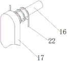
fig. 7 is the utility model discloses a connecting rod and stopper be connected the schematic diagram.
In the figure: 1. a base; 2. a first screw rod; 3. a support plate; 4. a baffle plate; 5. a display; 6. a host; 7. placing a bin; 8. a second screw rod; 9. a first gear; 10. a worm gear; 11. a worm; 12. a universal wheel; 13. a second gear; 14. a rotating rod; 15. a limiting disc; 16. a connecting rod; 17. a limiting block; 18. pushing the plate; 19. a tension spring; 20. connecting blocks; 21. positioning pins; 22. a torsion spring.
Detailed Description
The technical solutions in the embodiments of the present invention will be described clearly and completely with reference to the accompanying drawings in the embodiments of the present invention, and it is obvious that the described embodiments are only some embodiments of the present invention, not all embodiments. Based on the embodiments in the present invention, all other embodiments obtained by a person skilled in the art without creative work belong to the protection scope of the present invention.
In the description of the present invention, it should be noted that the terms "center", "upper", "lower", "left", "right", "vertical", "horizontal", "inner", "outer", and the like indicate orientations or positional relationships based on the orientations or positional relationships shown in the drawings, and are only for convenience of description and simplification of description, but do not indicate or imply that the device or element referred to must have a specific orientation, be constructed and operated in a specific orientation, and thus, should not be construed as limiting the present invention. Furthermore, the terms "first," "second," and "third" are used for descriptive purposes only and are not to be construed as indicating or implying relative importance. In the description of the present invention, it is to be noted that, unless otherwise explicitly specified or limited, the terms "mounted", "connected" and "disposed" are to be construed broadly, and may be, for example, fixedly connected, detachably connected, or integrally connected; can be mechanically or electrically connected; they may be connected directly or indirectly through intervening media, or they may be interconnected between two elements. The specific meaning of the above terms in the present invention can be understood in specific cases to those skilled in the art. The following describes an embodiment of the present invention according to its overall structure.
Referring to fig. 1 to 7, in an embodiment of the present invention, a computer teaching device capable of real-time monitoring and analysis includes a base 1, a positioning mechanism, and an adjusting mechanism, wherein a universal wheel 12 is disposed at the bottom of the base 1, a supporting plate 3 is disposed at the top end of the base 1, a placing chamber 7 is disposed at the inner side of the supporting plate 3, a host 6 is disposed inside the placing chamber 7, and a display 5 is disposed at the top end of the supporting plate 3;
the adjusting mechanism comprises a first gear 9 positioned inside a base 1, a second gear 13 is arranged inside the base 1 and positioned outside the first gear 9, a first screw rod 2 penetrating through the top end of the second gear 13 to the bottom of the second gear 13 is arranged at the top end of the second gear 13, a worm wheel 10 is arranged at the top of the first gear 9, a worm 11 is arranged inside the base 1 and positioned on one side of the worm wheel 10, a rotating rod 14 penetrating through the outer side of the base 1 is arranged at one end of the worm 11, a second screw rod 8 penetrating through the top of the base 1 is arranged at the top end of the worm wheel 10, and a baffle 4 is arranged outside the second screw rod 8 and positioned outside a support plate 3;
wherein, positioning mechanism is including being located the connecting rod 16 of placing storehouse 7 top, the one end of connecting rod 16 is provided with stopper 17, and the other end of connecting rod 16 is provided with spacing disc 15, the one end of placing storehouse 7 is provided with and runs through to the inside connecting block 20 of placing storehouse 7, the one end of connecting block 20 is located the inside of placing storehouse 7 and is provided with push pedal 18, the outside of connecting block 20 is provided with expanding spring 19, the top that one side of connecting block 20 is located expanding spring 19 is provided with locating pin 21, the outside of connecting rod 16 is provided with torsion spring 22.
Please refer to fig. 1 and 2, the first gear 9 is engaged with the latch on the outer side of the second gear 13, the inner side of the second gear 13 and the inner side of the base 1 are both provided with external threads matched with the first screw rod 2, and the outer side of the support plate 3 is provided with a sliding groove matched with the top of the first screw rod 2, so that the first screw rod 2 can move when the second gear 13 rotates.
Please refer to fig. 1 and 2, the worm wheel 10 is welded on the top of the first gear 9, and the worm 11 is engaged with the latch on the outer side of the worm wheel 10, so that the worm wheel 10 drives the first gear 9 to rotate.
Please refer to fig. 1 and 3, the inner side of the baffle 4 is provided with an external thread matching with the outer side of the second screw rod 8, and the length of the second screw rod 8 is greater than that of the baffle 4, so that the baffle 4 can be moved to the two ends of the display 5 conveniently.
Please refer to fig. 5, 6 and 7, one end of the limiting disc 15 is provided with a through hole matching with the positioning pin 21, and the connecting rod 16 is rotatably connected with the placing bin 7 through a torsion spring 22, so that the connecting rod 16 can rotate conveniently.
Please refer to fig. 5, one end of the extension spring 19 is welded to one side of the placing bin 7, and the other end of the extension spring 19 is welded to one side of the connecting block 20, so that the placing bin 7 and the connecting block 20 can be conveniently connected through the extension spring 19.
The utility model discloses a theory of operation is: when the device is used, the device can be moved through the universal wheel 12, when the device is moved to a designated position, the rotating rod 14 can be rotated, when the rotating rod 14 rotates, the worm wheel 10 can be rotated by driving the rotation of the worm 11, the worm wheel 10 can drive the second lead screw 8 and the first gear 9 to rotate, the first gear 9 can drive the second gear 13 to rotate when rotating, the second gear 13 can drive the first lead screw 2 limited by the support plate 3 to move when rotating, so that the bottom end of the first lead screw 2 is contacted with the ground, and the universal wheel 12 is separated from the ground, so that the device can be supported through the first lead screw 2, the placing stability of equipment is improved, when the second lead screw 8 rotates, the baffle 4 can move downwards along the second lead screw 8, and the display 5 is displayed, therefore, the equipment can be used, similarly, when the equipment is moved, the second screw rod 8 and the first gear 9 can be reversely rotated through reversely rotating the rotating rod 14, so that the first screw rod 2 is lifted, the universal wheel 12 can be contacted with the ground, meanwhile, the baffle plate 4 can be moved to two ends of the display 5, so as to shield the display 5, so that the display 5 is prevented from being damaged when the equipment is moved, the limiting block 17 can be rotated when the host machine 6 is required to be maintained, the limiting hole on the limiting disc 15 is aligned with the positioning pin 21 when the limiting block 17 rotates ninety degrees, then, the host machine in the placing bin 7 is taken out, meanwhile, the push plate 18 loses the extrusion force of the host machine 6 on the host machine, so that the telescopic spring 19 can be restored, the positioning pin 21 can be buckled into the limiting disc 15, the host machine 6 can be placed into the placing bin 7 after the maintenance of the host machine 6 is completed, when the host machine 6 pushes the push plate 18, the positioning pin 21 is separated from the limiting disc 15, and the torsion spring 22 is restored to drive the connecting rod 16 to swing, so that the limiting block 17 can be rotated to one end of the host machine 6, the host machine 6 can be shielded through the limiting block 17, and the host machine 6 is prevented from falling.
The above-mentioned, only be the concrete implementation of the preferred embodiment of the present invention, but the protection scope of the present invention is not limited thereto, and any person skilled in the art is in the technical scope of the present invention, according to the technical solution of the present invention and the utility model, the concept of which is equivalent to replace or change, should be covered within the protection scope of the present invention.
Claims (6)
1. A computer teaching device capable of monitoring and analyzing in real time comprises a base (1), a positioning mechanism and an adjusting mechanism, and is characterized in that universal wheels (12) are arranged at the bottom of the base (1), a supporting plate (3) is arranged at the top end of the base (1), a placing bin (7) is arranged on the inner side of the supporting plate (3), a host (6) is arranged inside the placing bin (7), and a display (5) is arranged at the top end of the supporting plate (3);
the adjusting mechanism comprises a first gear (9) located inside a base (1), a second gear (13) is arranged inside the base (1) and located on the outer side of the first gear (9), a first lead screw (2) penetrating through the bottom of the second gear (13) is arranged at the top end of the second gear (13), a worm wheel (10) is arranged at the top of the first gear (9), a worm (11) is arranged on one side of the worm wheel (10) inside the base (1), a rotating rod (14) penetrating through the outer side of the base (1) is arranged at one end of the worm (11), a second lead screw (8) penetrating through the upper portion of the base (1) is arranged at the top end of the worm wheel (10), and a baffle (4) is arranged on the outer side of the second lead screw (8) and located on the outer side of a supporting plate (3);
wherein, positioning mechanism is including being located connecting rod (16) of placing storehouse (7) top, the one end of connecting rod (16) is provided with stopper (17), and the other end of connecting rod (16) is provided with spacing disc (15), the one end of placing storehouse (7) is provided with and runs through to placing inside connecting block (20) of storehouse (7), the one end of connecting block (20) is located the inside of placing storehouse (7) and is provided with push pedal (18), the outside of connecting block (20) is provided with expanding spring (19), the top that one side of connecting block (20) is located expanding spring (19) is provided with locating pin (21), the outside of connecting rod (16) is provided with torsion spring (22).
2. The computer teaching device capable of real-time monitoring and analysis according to claim 1, wherein the first gear (9) is engaged with a latch on the outer side of the second gear (13), the inner side of the second gear (13) and the inner side of the base (1) are both provided with external threads matched with the first screw rod (2), and the outer side of the support plate (3) is provided with a sliding groove matched with the top of the first screw rod (2).
3. The computer teaching device capable of real-time monitoring and analysis according to claim 1, wherein the worm wheel (10) is welded on the top end of the first gear (9), and the worm (11) is meshed with a latch on the outer side of the worm wheel (10).
4. The computer teaching device capable of real-time monitoring and analysis according to claim 1, wherein the inner side of the baffle (4) is provided with external threads matched with the outer side of the second screw rod (8), and the length of the second screw rod (8) is greater than that of the baffle (4).
5. The computer teaching device capable of real-time monitoring and analysis according to claim 1, wherein one end of the limiting disc (15) is provided with a through hole matched with the positioning pin (21), and the connecting rod (16) is rotatably connected with the placing bin (7) through a torsion spring (22).
6. The computer teaching device capable of real-time monitoring and analysis according to claim 1, wherein one end of the extension spring (19) is welded to one side of the placing bin (7), and the other end of the extension spring (19) is welded to one side of the connecting block (20).
Priority Applications (1)
| Application Number | Priority Date | Filing Date | Title |
|---|---|---|---|
| CN202120982831.9U CN215000743U (en) | 2021-05-10 | 2021-05-10 | But real time monitoring analysis's computer teaching device |
Applications Claiming Priority (1)
| Application Number | Priority Date | Filing Date | Title |
|---|---|---|---|
| CN202120982831.9U CN215000743U (en) | 2021-05-10 | 2021-05-10 | But real time monitoring analysis's computer teaching device |
Publications (1)
| Publication Number | Publication Date |
|---|---|
| CN215000743U true CN215000743U (en) | 2021-12-03 |
Family
ID=79133288
Family Applications (1)
| Application Number | Title | Priority Date | Filing Date |
|---|---|---|---|
| CN202120982831.9U Expired - Fee Related CN215000743U (en) | 2021-05-10 | 2021-05-10 | But real time monitoring analysis's computer teaching device |
Country Status (1)
| Country | Link |
|---|---|
| CN (1) | CN215000743U (en) |
Cited By (1)
| Publication number | Priority date | Publication date | Assignee | Title |
|---|---|---|---|---|
| CN114673872A (en) * | 2022-02-25 | 2022-06-28 | 江苏峘宇建设有限公司 | Monitoring observation system based on construction engineering reconnaissance |
-
2021
- 2021-05-10 CN CN202120982831.9U patent/CN215000743U/en not_active Expired - Fee Related
Cited By (2)
| Publication number | Priority date | Publication date | Assignee | Title |
|---|---|---|---|---|
| CN114673872A (en) * | 2022-02-25 | 2022-06-28 | 江苏峘宇建设有限公司 | Monitoring observation system based on construction engineering reconnaissance |
| CN114673872B (en) * | 2022-02-25 | 2024-05-07 | 江苏峘宇建设有限公司 | Monitoring and observing system based on construction engineering investigation |
Similar Documents
| Publication | Publication Date | Title |
|---|---|---|
| CN215000743U (en) | But real time monitoring analysis's computer teaching device | |
| CN211454833U (en) | Demonstration device for practical training teaching based on computer application | |
| CN210836974U (en) | Education information display device | |
| CN210405527U (en) | Experiment examination system | |
| CN211669933U (en) | Information display device for audit | |
| CN215577570U (en) | Network promotion data analysis display device | |
| CN212805051U (en) | Computer software popularizes display device | |
| CN208335493U (en) | Device is explained and publicised in a kind of teaching of China and foreign countries' history of art | |
| CN213424241U (en) | Teaching aid suitable for economics are given lessons and are used in practice | |
| CN216957386U (en) | Display device | |
| CN111439054A (en) | Display device for English teaching and use method thereof | |
| CN215576356U (en) | Display for computer system teaching | |
| CN111210701A (en) | Mathematical matrix teaching model with computer display function | |
| CN215000569U (en) | Admire class and record effect display screen convenient to control demonstration angle | |
| CN219590956U (en) | Word filling device | |
| CN212724479U (en) | A speech board for assembly type building teaching | |
| CN215526945U (en) | Teaching material placer is used in teaching that facilitates use | |
| CN216556216U (en) | Distance education device that education and training used | |
| CN216353075U (en) | Movable and liftable large-size education conference machine | |
| CN214928504U (en) | Adjustable blackboard for music teaching | |
| CN216416420U (en) | Drawing device for building electrical teaching | |
| CN212400729U (en) | Building engineering cost budget rehearsal device | |
| CN214467494U (en) | Efficient mapping equipment for engineering cost | |
| CN219120169U (en) | Fast assembly's teaching display device | |
| CN215868297U (en) | Think political affairs class teaching display device |
Legal Events
| Date | Code | Title | Description |
|---|---|---|---|
| GR01 | Patent grant | ||
| GR01 | Patent grant | ||
| CF01 | Termination of patent right due to non-payment of annual fee |
Granted publication date: 20211203 |
|
| CF01 | Termination of patent right due to non-payment of annual fee |