CN214998830U - Self-aligning rolling bearing - Google Patents
Self-aligning rolling bearing Download PDFInfo
- Publication number
- CN214998830U CN214998830U CN202120905702.XU CN202120905702U CN214998830U CN 214998830 U CN214998830 U CN 214998830U CN 202120905702 U CN202120905702 U CN 202120905702U CN 214998830 U CN214998830 U CN 214998830U
- Authority
- CN
- China
- Prior art keywords
- inner ring
- rolling bearing
- convex arc
- bearing according
- rollers
- Prior art date
- Legal status (The legal status is an assumption and is not a legal conclusion. Google has not performed a legal analysis and makes no representation as to the accuracy of the status listed.)
- Active
Links
Images
Landscapes
- Rolling Contact Bearings (AREA)
Abstract
The utility model relates to a bearing technical field specifically is a relate to a self-aligning antifriction bearing belongs to the special-shaped structure bearing, include: the roller bearing comprises an outer ring, an inner ring, rollers and a retainer, wherein the inner ring is in an outward convex arc lengthened shape, the rollers are arranged in a clearance between the inner ring and the outer ring, the rollers are double-row rolling bodies which are arranged between the inner ring and the outer ring through the retainer, and the outer ring is in a split type two-body structure; the utility model discloses a self-aligning antifriction bearing is from aligning strong, bearing capacity is big, and bearing part intensity is high, and life is high, can satisfy different customers' operation requirement.
Description
Technical Field
The utility model relates to a bearing technical field specifically is a relate to a self-aligning antifriction bearing belongs to the special-shaped structure bearing.
Background
The common self-aligning rolling bearing mostly adopts a form of assembling a drum-shaped roller between an inner ring with two raceways and an outer ring with one raceway being a spherical surface, namely, the roller raceway surface is in a convex design, the structure is single, and the self-aligning performance is limited. The self-aligning roller bearing mainly bears radial load and can bear axial load in any direction, and the self-aligning roller bearing has the capability of automatically aligning and bearing heavy radial load.
However, with the wide demand of customers, the use requirement of the self-aligning bearing is also improved, so that the self-aligning bearing with a special structure, which has strong self-aligning performance and large bearing capacity, needs to be developed.
Disclosure of Invention
In view of the above technical problem, the utility model aims at providing a self-aligning antifriction bearing has automatic alignment nature, characteristics that bearing capacity is big.
In order to realize the purpose, the utility model discloses the technical scheme who adopts is: self-aligning rolling bearing comprising: the roller bearing comprises an outer ring, an inner ring, rollers and a retainer, wherein the inner ring is in an outward convex arc lengthened shape, the rollers are arranged in a clearance between the inner ring and the outer ring, the rollers are double-row rolling bodies which are arranged between the inner ring and the outer ring through the retainer, and the outer ring is in a split type two-body structure;
furthermore, the width of the inner ring is larger than the distance between the two outer end faces of the two split outer rings after installation;
furthermore, the inner ring is provided with a convex arc section position, and two sides of the convex arc section position are straight line section positions;
furthermore, the two rows of rollers are arranged at the position of a convex arc section of the outer diameter of the inner ring;
furthermore, the center of a convex arc section of the outer diameter of the inner ring is a boundary, the two rows of rollers are symmetrically arranged by taking the central boundary as a boundary, and the outer end surfaces of the two rows of rollers are respectively flush with the end points of two ends of the convex arc section;
furthermore, the surface of the roller is of an inwards concave structure, and the radian of the inwards concave structure is matched with the radian of a convex arc of the inner ring;
furthermore, the raceway of the outer ring of the two-body structure is convex, and the convex radian is matched with the concave radian on the surface of the roller.
Furthermore, the two rows of rollers are assembled through respective retainers, the two retainers are symmetrically arranged by the central limit of the inner ring convex arc section, and the two retainers form an included angle towards the central limit direction;
furthermore, two ends of each retainer respectively extend out of two end faces of the roller, and the extending end of each retainer close to the central limit direction is of an L-shaped structure;
furthermore, the two L-shaped retainers are arranged oppositely, and a gap is arranged between the two L-shaped retainers; the retainer has simple structure, easy processing, low friction coefficient with the rolling body and no noise of the bearing, and is beneficial to lubrication;
furthermore, the retainer is made of nylon.
By adopting the structure of the concave rollers and the convex inner and outer ring raceways, the structure is more favorable for the free aligning of the bearing, the aligning limit of the original outer ring integrated structure is too small, and the rotation speed of the bearing can be improved due to the self-guiding of the retainer rollers; the ball bearing can replace a self-aligning ball bearing under the condition of the same size series, and compared with a self-aligning ball with the same specification, the bearing capacity is about 2 times larger.
The utility model has the advantages that:
the utility model discloses a self-aligning antifriction bearing is from aligning strong, bearing capacity is big, and bearing part intensity is high, and life is high, can satisfy different customers' operation requirement.
Drawings
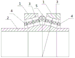
Fig. 1 is a structural diagram of the present invention.
In the figure, 1, outer ring, 2, inner ring, 3, roller, 4, cage, 5, center limit.
Detailed Description
The present invention will be further explained with reference to the accompanying drawings.
As shown in fig. 1, a self-aligning rolling bearing includes: the roller-type double-row rolling bearing comprises an outer ring 1, an inner ring 2, rollers 3 and a retainer 4, wherein the inner ring 1 is in an outer convex arc lengthened shape, the rollers 3 are arranged in a clearance between the inner ring 2 and the outer ring 1, the rollers 3 are double-row rolling bodies arranged between the inner ring 2 and the outer ring 1 through the retainer 4, and the outer ring 1 is in a split type two-body structure;
further, the width of the inner ring 2 is larger than the distance between the two outer end faces of the two split outer rings 1 after installation;
furthermore, the inner ring 2 is provided with a convex arc section position, and two sides of the convex arc section position are straight line section positions;
further, the two rows of rollers 3 are arranged at the position of a convex arc section of the outer diameter of the inner ring 2;
furthermore, the center of a convex arc section of the outer diameter of the inner ring 2 is a boundary, the two rows of rollers 4 are symmetrically arranged by taking the central boundary as a boundary, and the outer end surfaces of the two rows of rollers 3 are respectively flush with the end points of two ends of the convex arc section;
furthermore, the surface of the roller 3 is of an inwards concave structure, and the radian of the inwards concave structure is matched with the radian of a convex arc of the inner ring 2;
furthermore, the raceway of the outer ring 1 of the two-body structure is convex, and the convex radian is matched with the concave radian on the surface of the roller 3.
Furthermore, the two rows of rollers 3 are respectively assembled through respective cages 4, the two cages 4 are symmetrically arranged by the central limit 5 of the convex arc section of the inner ring 2, and the two cages 4 both form an included angle towards the direction of the central limit;
furthermore, two ends of each retainer 4 respectively extend out of two end faces of the roller 3, and the extending end of each retainer 4 close to the central limit 5 is of an L-shaped structure;
further, two L-shaped holders 4 are arranged facing each other with a gap therebetween.
It is to be understood that the above-described embodiments are only some, and not all, embodiments of the present invention. Based on the embodiments in the present invention, all other embodiments obtained by a person skilled in the art without creative work belong to the protection scope of the present invention.
Claims (10)
1. Self-aligning rolling bearing comprising: outer lane, inner circle, roller and holder, its characterized in that: the inner ring is in an outer convex arc lengthened shape, the roller is arranged in a clearance between the inner ring and the outer ring, the roller is a double-row rolling body arranged between the inner ring and the outer ring through a retainer, and the outer ring is in a split type two-body structure.
2. Self aligning rolling bearing according to claim 1, characterized in that: the width of the inner ring is larger than the distance between the two outer end faces of the two split outer rings after installation.
3. Self aligning rolling bearing according to claim 1, characterized in that: the inner ring is provided with a convex arc section position, and two sides of the convex arc section position are straight line section positions.
4. Self aligning rolling bearing according to claim 3, characterized in that: the two rows of rollers are arranged at the position of the convex arc section of the outer diameter of the inner ring.
5. Self aligning rolling bearing according to claim 3, characterized in that: the center of the convex arc section of the outer diameter of the inner ring is used as a boundary, the two rows of rollers are symmetrically arranged by taking the center boundary, and the outer end surfaces of the two rows of rollers are respectively flush with the end points of the two ends of the convex arc section.
6. Self aligning rolling bearing according to claim 5, characterized in that: the surface of the roller is of an inwards concave structure, and the radian of the inwards concave structure is matched with the radian of the convex arc of the inner ring.
7. Self aligning rolling bearing according to claim 6, characterized in that: the raceway of the outer ring of the two-body structure is convex and the convex radian is matched with the concave radian on the surface of the roller.
8. Self aligning rolling bearing according to claim 5, characterized in that: the two rows of rollers are assembled through respective retainers, the two retainers are symmetrically arranged in the central limit of the inner ring convex arc section, and the two retainers form an included angle in the direction of the central limit.
9. Self aligning rolling bearing according to claim 8, characterized in that: two ends of each retainer respectively extend out of two end faces of the roller, and the extending end of each retainer close to the central limit direction is of an L-shaped structure.
10. Self aligning rolling bearing according to claim 9, characterized in that: the two L-shaped retainers are arranged opposite to each other with a gap between them.
Priority Applications (1)
| Application Number | Priority Date | Filing Date | Title |
|---|---|---|---|
| CN202120905702.XU CN214998830U (en) | 2021-04-29 | 2021-04-29 | Self-aligning rolling bearing |
Applications Claiming Priority (1)
| Application Number | Priority Date | Filing Date | Title |
|---|---|---|---|
| CN202120905702.XU CN214998830U (en) | 2021-04-29 | 2021-04-29 | Self-aligning rolling bearing |
Publications (1)
| Publication Number | Publication Date |
|---|---|
| CN214998830U true CN214998830U (en) | 2021-12-03 |
Family
ID=79093249
Family Applications (1)
| Application Number | Title | Priority Date | Filing Date |
|---|---|---|---|
| CN202120905702.XU Active CN214998830U (en) | 2021-04-29 | 2021-04-29 | Self-aligning rolling bearing |
Country Status (1)
| Country | Link |
|---|---|
| CN (1) | CN214998830U (en) |
-
2021
- 2021-04-29 CN CN202120905702.XU patent/CN214998830U/en active Active
Similar Documents
| Publication | Publication Date | Title |
|---|---|---|
| US8939651B2 (en) | Multi-row tapered roller bearing and transmission having such a bearing | |
| CN213393145U (en) | Self-aligning roller bearing | |
| CN214998830U (en) | Self-aligning rolling bearing | |
| CN210949556U (en) | Ball retainer and angular contact ball bearing | |
| CN216691865U (en) | Main bearing of heading machine | |
| KR20210098633A (en) | A Rolling Bearing Having Variable Rated Capacity And Roller For Rolling Bearing | |
| CN114321168A (en) | Main bearing of heading machine | |
| CN212615911U (en) | High-precision self-aligning roller bearing for fan | |
| CN103352919B (en) | Solid cage and reinforced solid tapered roller bearing | |
| CN214661502U (en) | Rolling mill roller single-row cylindrical bearing with retainer | |
| CN214698789U (en) | Self-aligning roller bearing | |
| CN211693222U (en) | Ball bearing raceway with heart-shaped curvature | |
| WO2021109581A1 (en) | Ball retainer and angular contact ball bearing | |
| CN210799723U (en) | Four-point contact type high-speed lead screw bearing | |
| CN203395023U (en) | Solid retainer and reinforced solid tapered roller bearing | |
| CN217130093U (en) | Self-aligning roller bearing capable of bearing radial force and larger one-way axial force | |
| CN113175478A (en) | Concave spherical surface cylindrical roller bearing | |
| CN111188831A (en) | Ferrule guide type thrust cylindrical roller bearing | |
| CN101782107A (en) | Pure rolling bearing | |
| CN218152001U (en) | Enhanced guide type light series tapered roller bearing | |
| CN220101803U (en) | Double-row serial integrated high-precision angular contact ball bearing | |
| CN211901274U (en) | Solid retainer thrust cylindrical roller bearing | |
| CN216618264U (en) | Deep groove ball and cylindrical roller composite bearing | |
| CN221974080U (en) | Single-row angular contact spherical self-aligning roller bearing | |
| EP4227548A1 (en) | Angular contact self-aligning roller bearing |
Legal Events
| Date | Code | Title | Description |
|---|---|---|---|
| GR01 | Patent grant | ||
| GR01 | Patent grant |