CN214982275U - Machine tool chuck - Google Patents
Machine tool chuck Download PDFInfo
- Publication number
- CN214982275U CN214982275U CN202121239831.6U CN202121239831U CN214982275U CN 214982275 U CN214982275 U CN 214982275U CN 202121239831 U CN202121239831 U CN 202121239831U CN 214982275 U CN214982275 U CN 214982275U
- Authority
- CN
- China
- Prior art keywords
- rotary drum
- movable rod
- box
- machine tool
- tool chuck
- Prior art date
- Legal status (The legal status is an assumption and is not a legal conclusion. Google has not performed a legal analysis and makes no representation as to the accuracy of the status listed.)
- Active
Links
Images


Abstract
The utility model provides a machine tool chuck, the power distribution box comprises a box body, the preceding bolt of box has the chassis, the front portion on chassis rotates and is connected with the rotary drum, the preceding sliding connection of rotary drum has a plurality of tight pieces that press from both sides that are the circumference array and distribute, the interior back of the body wall fixed mounting of box has and drives actuating cylinder, the anterior output that drives actuating cylinder rotates and is connected with the movable rod, the movable rod cup joints with the interior back of the body wall activity of rotary drum, the movable rod can not take place to rotate for the chassis, the anterior week side activity of movable rod articulates has and presss from both sides the corresponding connecting rod of tight piece, and the tip of connecting rod is articulated mutually with pressing from both sides tight piece. The utility model discloses a place the preceding center department at the rotary drum with graphite work piece, drive the flexible transmission that passes through movable rod and connecting rod of actuating cylinder and can drive and press from both sides tight piece and draw close to the center and carry out the centre gripping to graphite work piece, because graphite work piece is square, can be better carry out the centre gripping to graphite work piece fixed, the setting of pressing from both sides tight post has further improved the centre gripping effect.
Description
Technical Field
The utility model relates to the technical field of machining, especially, relate to a machine tool chuck.
Background
Graphite has special properties such as high temperature resistance, electrical conductivity, thermal conductivity, lubricity, chemical stability, plasticity, thermal shock resistance and the like, and therefore, graphite is widely used in industrial production.
When a graphite workpiece is machined, machining operations such as milling, drilling, boring and the like are often required to be performed through graphite, the clamping effect of the existing chucks for machine tools on the square graphite workpiece is poor, and the use requirements are not met.
Disclosure of Invention
In order to solve the technical problems in the prior art, it is necessary to provide a machine tool chuck.
A machine tool chuck comprises a box body, a chassis is bolted at the front of the box body, a rotary drum is rotatably connected at the front part of the chassis, the front of the rotating cylinder is connected with a plurality of clamping blocks distributed in a circumferential array in a sliding way, the inner back wall of the box body is fixedly provided with a driving cylinder, the front output end of the driving cylinder is rotatably connected with a movable rod which is movably sleeved with the inner back wall of the rotary drum and can not rotate relative to the chassis, the front peripheral side surface of the movable rod is movably hinged with a connecting rod corresponding to the clamping block, and the end part of the connecting rod is hinged with the clamping block, a graphite workpiece is placed in the front center of the rotary drum, the driving cylinder stretches and retracts, the clamping block can be driven to approach to the center through the transmission of the movable rod and the connecting rod, and the graphite workpiece is clamped.
The utility model discloses a graphite workpiece processing device, including box, driving motor, gear and movable rod, the back center of rotary drum department fixed mounting has the ring gear, the ring gear is located the week side of movable rod, the inside of box still fixed mounting has driving motor, driving motor's output fixed mounting has the gear, the gear meshes with the ring gear mutually, and driving motor rotates and can drive the rotary drum fast turn-round through gear and movable rod, is convenient for process the graphite workpiece, driving motor's bottom is provided with the backup pad, driving motor fixed mounting is at the top of backup pad, the backup pad is used for fixing driving motor with the interior antetheca fixed connection of box, backup pad.
The upper surface of rotary drum has set up a plurality of slide rails admittedly, the spout has been seted up in the front of slide rail, the back fixed mounting who presss from both sides tight piece has the slider, slider sliding connection is in the spout, and the cooperation of slider and spout can make and press from both sides tight piece and keep stable to the motion in-process of graphite work piece centre gripping, the one end that the movable rod was kept away from to the connecting rod is articulated with the back activity of slider.
The front center of the rotary drum is fixedly provided with a supporting block which can be used for placing a graphite workpiece, the surface of one side, close to the supporting block, of the clamping block is fixedly connected with clamping columns, the clamping columns are distributed in a circumferential array mode relative to the supporting block, the clamping columns can increase the contact surface with the graphite workpiece, and therefore the clamping effect on the graphite workpiece is improved.
The utility model adopts the above technical scheme, compare with prior art, its beneficial effect lies in: the utility model discloses an including the box, the preceding bolt of box has the chassis, the front portion on chassis rotates and is connected with the rotary drum, the preceding sliding connection of rotary drum has a plurality of clamping blocks that are circumference array distribution, the interior back wall fixed mounting of box has the actuating cylinder, the anterior output of actuating cylinder rotates and is connected with the movable rod, the movable rod cup joints with the activity of the interior back wall of rotary drum, the movable rod can not take place to rotate for the chassis, the anterior week side activity of movable rod articulates there is the connecting rod corresponding with clamping block, and the tip of connecting rod articulates with clamping block mutually, place the graphite work piece in the preceding center of rotary drum, actuating cylinder is flexible can drive clamping block and draw close to the center and carry out the centre gripping to the graphite work piece through the transmission of movable rod and connecting rod; the utility model discloses it can drive through the transmission of movable rod and connecting rod that actuating cylinder is flexible and press from both sides tight piece and draw close to the center and carry out the centre gripping to graphite work piece, because graphite work piece is square, can be better carry out the centre gripping to graphite work piece fixed, press from both sides the setting of tight post multiplicable and graphite work piece's contact surface, further improved the centre gripping effect, driving motor rotates and can drive the rotary drum through gear and movable rod and rotate fast, is convenient for process graphite work piece when not influencing the centre gripping effect.
Drawings
In order to more clearly illustrate the technical solutions of the embodiments of the present invention, the drawings used in the description of the embodiments will be briefly introduced below, and it is obvious that the drawings in the following description are only some embodiments of the present invention, and it is obvious for those skilled in the art that other drawings can be obtained according to these drawings without creative efforts.
Fig. 1 is a schematic view of the overall structure of the present invention;
fig. 2 is an overall structure front view of the present invention;
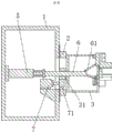
fig. 3 is a schematic cross-sectional view of a-a in fig. 2 according to the present invention;
fig. 4 is an enlarged view of a portion a in fig. 1 according to the present invention.
In the figure: 1. a box body; 2. a chassis; 3. a rotating drum; 31. a ring gear; 32. a resisting block; 4. a clamping block; 41. a slide rail; 4101. a chute; 42. a slider; 43. clamping the column; 5. a driving cylinder; 6. a movable rod; 61. a connecting rod; 7. a drive motor; 71. a gear.
Detailed Description
In order to more clearly illustrate the technical solutions of the embodiments of the present invention, the drawings required to be used in the embodiments will be briefly described below, and it is obvious that the drawings in the following description are some embodiments of the present invention, and it is obvious for those skilled in the art to obtain other drawings without creative efforts.
Referring to fig. 1 to 4, an embodiment of the present invention provides a machine tool chuck, which includes a box 1, a chassis 2 is bolted to the front of the box 1, a rotary drum 3 is rotatably connected to the front of the chassis 2, a plurality of clamping blocks 4 distributed in a circumferential array are slidably connected to the front of the rotary drum 3, a driving cylinder 5 is fixedly installed on the inner back wall of the box 1, a movable rod 6 is rotatably connected to the front output end of the driving cylinder 5, the movable rod 6 is movably sleeved with the inner back wall of the rotary drum 3, the movable rod 6 is not rotatable relative to the chassis 2, a connecting rod 61 corresponding to the clamping block 4 is movably hinged to the front circumferential side of the movable rod 6, the end of the connecting rod 61 is hinged to the clamping block 4, a graphite workpiece is placed at the front center of the rotary drum 3, the driving cylinder 5 can drive the clamping block 4 to approach to the center and clamp the graphite workpiece through the transmission of the movable rod 6 and the connecting rod 61, because the graphite workpiece is square, the graphite workpiece can be better clamped and fixed.
Fixed mounting has ring gear 31 at the back center department of rotary drum 3, ring gear 31 is located the week side of movable rod 6, the inside of box 1 is fixed mounting still has driving motor 7, driving motor 7's output fixed mounting has gear 71, gear 71 meshes with ring gear 31 mutually, driving motor 7 rotates and can drive rotary drum 3 through gear 71 and movable rod 6 and rotate fast, be convenient for process the graphite work piece, driving motor 7's bottom is provided with the backup pad, driving motor 7 fixed mounting is at the top of backup pad, backup pad and box 1's interior antetheca fixed connection, the backup pad is used for fixing driving motor 7.
The upper surface of the rotary drum 3 is fixedly embedded with a plurality of sliding rails 41, the front of each sliding rail 41 is provided with a sliding groove 4101, the back of the clamping block 4 is fixedly provided with a sliding block 42, the sliding block 42 is connected in the sliding groove 4101 in a sliding manner, the clamping block 4 can keep stable in the motion process of clamping a graphite workpiece through the matching of the sliding block 42 and the sliding groove 4101, and one end of the connecting rod 61, which is far away from the movable rod 6, is movably hinged with the back of the sliding block 42.
The front center of the rotary drum 3 is fixedly provided with a supporting block 32, the supporting block 32 can be used for placing graphite workpieces, one side surface of the clamping block 4 close to the supporting block 32 is fixedly connected with clamping columns 43, the clamping columns 43 are distributed in a circumferential array mode relative to the supporting block 32, the clamping columns 43 can increase contact surfaces with the graphite workpieces, and therefore clamping effects on the graphite workpieces are improved.
The embodiment is a method for using a machine tool chuck: as shown in fig. 1-4, the driving cylinder 5 is started, the driving cylinder 5 is stretched and contracted to drive the clamping block 4 to approach to the center and clamp the graphite workpiece through the transmission of the movable rod 6 and the connecting rod 61, the graphite workpiece can be better clamped and fixed because the graphite workpiece is square, the driving motor 7 rotates to drive the rotary drum 3 to rotate rapidly through the gear 71 and the movable rod 6, the graphite workpiece is convenient to process, the driving cylinder 5 can be an SMC type MBB cylinder, and the driving motor 7 is JS-50 in model.
In the description herein, references to the description of "one embodiment," "an example," "a specific example," etc., mean that a particular feature, structure, material, or characteristic described in connection with the embodiment or example is included in at least one embodiment or example of the invention. In this specification, the schematic representations of the terms used above do not necessarily refer to the same embodiment or example. Furthermore, the particular features, structures, materials, or characteristics described may be combined in any suitable manner in any one or more embodiments or examples.
The preferred embodiments of the present invention disclosed above are intended only to help illustrate the present invention. The preferred embodiments are not intended to be exhaustive or to limit the invention to the precise embodiments disclosed. Obviously, many modifications and variations are possible in light of the above teaching. The embodiments were chosen and described in order to best explain the principles of the invention and its practical applications, to thereby enable others skilled in the art to best understand the invention for and utilize the invention. The present invention is limited only by the claims and their full scope and equivalents.
Claims (6)
1. The utility model provides a machine tool chuck, includes the box, its characterized in that: the front of the box is bolted with a chassis, the front of the chassis is rotationally connected with a rotary drum, the front of the rotary drum is slidably connected with a plurality of clamping blocks distributed in a circumferential array, the inner back wall of the box is fixedly provided with a driving cylinder, the front output end of the driving cylinder is rotationally connected with a movable rod, the movable rod is movably sleeved with the inner back wall of the rotary drum, the front circumferential side surface of the movable rod is movably hinged with a connecting rod corresponding to the clamping blocks, and the end part of the connecting rod is hinged with the clamping blocks.
2. The machine tool chuck according to claim 1, wherein: the back center department fixed mounting of rotary drum has the ring gear, the ring gear is located the week side of movable rod, the inside still fixed mounting of box has driving motor, driving motor's output fixed mounting has the gear, the gear meshes with the ring gear mutually.
3. The machine tool chuck according to claim 2, wherein: the bottom of driving motor is provided with the backup pad, driving motor fixed mounting is at the top of backup pad, the backup pad is with the interior antetheca fixed connection of box.
4. The machine tool chuck according to claim 1, wherein: the upper surface of rotary drum has embedded a plurality of slide rails, the spout has been seted up in the front of slide rail, the back fixed mounting who presss from both sides tight piece has the slider, slider sliding connection is in the spout.
5. The machine tool chuck according to claim 4, wherein: one end of the connecting rod, which is far away from the movable rod, is movably hinged with the back of the sliding block.
6. The machine tool chuck according to claim 1, wherein: the front center of the rotary drum is fixedly provided with a resisting block, the surface of one side, close to the resisting block, of the clamping block is fixedly connected with clamping columns, and the clamping columns are distributed in a circumferential array mode relative to the resisting block.
Priority Applications (1)
| Application Number | Priority Date | Filing Date | Title |
|---|---|---|---|
| CN202121239831.6U CN214982275U (en) | 2021-06-04 | 2021-06-04 | Machine tool chuck |
Applications Claiming Priority (1)
| Application Number | Priority Date | Filing Date | Title |
|---|---|---|---|
| CN202121239831.6U CN214982275U (en) | 2021-06-04 | 2021-06-04 | Machine tool chuck |
Publications (1)
| Publication Number | Publication Date |
|---|---|
| CN214982275U true CN214982275U (en) | 2021-12-03 |
Family
ID=79086207
Family Applications (1)
| Application Number | Title | Priority Date | Filing Date |
|---|---|---|---|
| CN202121239831.6U Active CN214982275U (en) | 2021-06-04 | 2021-06-04 | Machine tool chuck |
Country Status (1)
| Country | Link |
|---|---|
| CN (1) | CN214982275U (en) |
-
2021
- 2021-06-04 CN CN202121239831.6U patent/CN214982275U/en active Active
Similar Documents
| Publication | Publication Date | Title |
|---|---|---|
| CN210281473U (en) | Clamping device for machining that suitability is strong | |
| CN210209983U (en) | Numerical control machining machine tool for tungsten steel grinding head | |
| CN213317862U (en) | Lathe convenient to multi-angle centre gripping is fixed | |
| CN107511703A (en) | A kind of hardware workpiece fixture for processing | |
| CN214982275U (en) | Machine tool chuck | |
| CN215033734U (en) | Chuck with adjustable clamping length for machine tool | |
| CN210335212U (en) | Novel drilling clamp for multi-spindle drilling machine | |
| CN218639047U (en) | Cutting and polishing integrated machine for numerical control machining fixed block | |
| CN217474859U (en) | Can collect numerical control lathe for parts machining of smear metal | |
| CN215919308U (en) | Workpiece deburring device | |
| CN212192126U (en) | Tool chuck for edge milling machine | |
| CN213258132U (en) | Multifunctional workbench for machining | |
| CN213319226U (en) | Tip grinding machanism of titanium alloy thin wall seamless pipe | |
| CN212351498U (en) | Clamping mechanism for mold forming grinding | |
| CN213559934U (en) | High-precision numerical control lathe | |
| CN213052776U (en) | Numerical control lathe processing clamping device | |
| CN210059862U (en) | Novel multi-position adjustable radial drilling machine | |
| CN209868306U (en) | Intelligent fixing and clamping device for honing machine | |
| CN211867486U (en) | Based on numerical control lathe is with fixed clamping device | |
| CN112139556A (en) | Large workpiece end face boring device for machining | |
| CN219152113U (en) | Workpiece placement device | |
| CN215616416U (en) | Hydraulic flat head milling machine | |
| CN219094409U (en) | Prevent pressing from both sides damage lathe anchor clamps | |
| CN219649833U (en) | Auxiliary clamping mechanism for precision industrial ceramic processing | |
| CN204353513U (en) | Multi-station rotary-disk boring machine |
Legal Events
| Date | Code | Title | Description |
|---|---|---|---|
| GR01 | Patent grant | ||
| GR01 | Patent grant |