CN214936575U - Industrial sewage filtering device - Google Patents
Industrial sewage filtering device Download PDFInfo
- Publication number
- CN214936575U CN214936575U CN202023074559.9U CN202023074559U CN214936575U CN 214936575 U CN214936575 U CN 214936575U CN 202023074559 U CN202023074559 U CN 202023074559U CN 214936575 U CN214936575 U CN 214936575U
- Authority
- CN
- China
- Prior art keywords
- pipe
- filter
- wall
- cylinder body
- shaped pipe
- Prior art date
- Legal status (The legal status is an assumption and is not a legal conclusion. Google has not performed a legal analysis and makes no representation as to the accuracy of the status listed.)
- Active
Links
Images


Landscapes
- Water Treatment By Sorption (AREA)
Abstract
The utility model discloses an industrial sewage filtering device, which relates to the technical field of sewage filtering and comprises a cylinder body and a flange cover, wherein the flange cover is positioned right above the cylinder body, a flange plate is welded on the upper surface of the cylinder body, a base is welded on the lower surface of the cylinder body, a water inlet pipe communicated with the inside of the cylinder body is arranged above the left side of the outer wall of the cylinder body, a water outlet pipe is arranged below the right side of the outer wall of the cylinder body, the water inlet pipe and the water outlet pipe both penetrate into the inside of the cylinder body, and two partition plates which are distributed at equal intervals are embedded in the inner wall of the cylinder body; the beneficial effects of the utility model reside in that: realize longer filtration stroke through U type pipe, promoted the filter effect, progressively filter sewage through level filter equipment for different impurity is by the filtration of batch, and the suitability is more extensive when filtering more thoroughly, and the mode of setting up of filter screen makes its inside difficult gathering impurity, has avoided the trouble of frequent change and clearance filter screen.
Description
Technical Field
The utility model belongs to the technical field of the sewage filtration technique and specifically relates to a sewage filter for industry is related to.
Background
The wastewater treatment is to treat wastewater by physical, chemical and biological methods, so that the wastewater is purified, the pollution is reduced, the wastewater is recycled and reused, water resources are fully utilized, various kinds of wastewater can be produced in industrial production, and the types and the concentrations of the wastewater produced in different industries have obvious differences. Traditional industrial sewage filter equipment exists the problem that the filtration stroke is shorter, easily leads to sewage to filter thoroughly, only possesses comparatively single filter layer moreover usually, and the filter effect is not good, and the remaining impurity in aquatic is more, and again, general industrial sewage filter equipment's filter screen content easily adheres to impurity, leads to the filter screen to need often to change, and is very inconvenient.
SUMMERY OF THE UTILITY MODEL
The utility model aims at the problem and the not enough of above-mentioned existence, provide a industrial sewage filter equipment who passes through.
In order to achieve the purpose, the adopted technical scheme is as follows:
an industrial sewage filtering device comprises a barrel and a flange cover, wherein the flange cover is positioned right above the barrel, a flange plate is welded on the upper surface of the barrel, a base is welded on the lower surface of the barrel, a water inlet pipe communicated with the interior of the barrel is arranged above the left side of the outer wall of the barrel, a water outlet pipe is arranged below the right side of the outer wall of the barrel, the water inlet pipe and the water outlet pipe penetrate through the interior of the barrel, two partition plates which are distributed at equal intervals are embedded in the inner wall of the barrel, a sedimentation tank is arranged in the middle of the upper surface of the partition plate on the upper side, and the left end of the sedimentation tank is connected with and communicated with the right end of the water inlet pipe;
the left side and the right side of the upper surface of the flange cover are welded with two symmetrically distributed handles, the outer side of the upper surface of the flange cover is in threaded connection with a circle of bolts which are distributed at equal intervals, the flange cover is fixedly connected with the flange plate through a plurality of bolts, the middle of the upper surface of the flange cover is connected with an exhaust pipe, the exhaust pipe is positioned between the two handles, the lower end of the exhaust pipe penetrates into the flange cover, the exhaust pipe is inserted into the upper surface of the sedimentation tank and is communicated with the interior of the sedimentation tank, the right side of the upper surface of the flange cover is fixedly provided with a motor which is arranged downwards, and the motor is positioned on the right side of the handle on the right side;
two fixed mounting has U type pipe between the baffle, just U type pipe right side upper end runs through out the upside the upper surface of baffle, U type pipe right side upper end with the sedimentation tank communicates with each other, the equal fixed mounting of U type intraductal inside below bend has the collet, just activated carbon has been arranged in the collet, be equipped with four filter screens in the middle of the U type intraductal wall, the surface all is equipped with the holding ring about the filter screen, just the filter screen passes through the holding ring can dismantle connect in the middle of the U type intraductal wall, U type pipe left side lower extreme runs through out the downside the lower surface of baffle, just U type pipe left side lower extreme with the left end of outlet pipe is connected and is communicated with, the outlet pipe with can dismantle between the U type pipe left side lower extreme and be connected with the filter core.
Furthermore, the inner wall of the U-shaped pipe and the outer wall of the positioning ring are provided with threads which are matched with each other.
Furthermore, the filtering density of the four filter screens is increased from right to left.
Further, the interior of the filter element is made of hollow fiber membrane silk materials in a high-density packaging mode.
Furthermore, the lower end of the motor is in transmission connection with a screw, and the lower end of the screw extends into the upper end of the right side of the U-shaped pipe.
Further, the inside below of barrel be equipped with the communicating blow off pipe of filter core afterbody, the head end of blow off pipe peg graft in the right side of filter core, just the blow off pipe tail end runs through the outer wall of barrel left side and communicates with each other with the external world.
By adopting the technical scheme, the beneficial effects are as follows:
a user can put a flocculating agent into the sedimentation tank through the exhaust pipe to primarily precipitate solid impurities in sewage as a means for strengthening solid-liquid separation, the sedimentation tank is positioned above the inner part of the cylinder body and is close to the flange cover, the user is very convenient when cleaning stains at the bottom of the sedimentation tank, as the motor drives the screw rod to continuously rotate in water flow, the flowing speed of the water flow is greatly accelerated, the filtering speed is also accelerated, the distribution of the impurities in the water flow is more uniform, the subsequent filtering is convenient, as the filtering densities of the four filter screens are sequentially increased, insoluble impurities in the water flow are sequentially filtered by the filter screens from large to small, the impurities are filtered more thoroughly, the filtering pressure born by each filter screen is smaller, the service life of the filter screens is prolonged, the impurities filtered by the filter screens are adsorbed in falling into active carbon, the residual impurities in the filter screens are greatly reduced, and the time for replacing and cleaning the filter screens is saved greatly, the continuous operation efficiency of the filtering device is greatly increased, the filtering stroke is greatly increased due to the design of the U-shaped pipe, the filtering time of sewage in the U-shaped pipe is longer, and the filtering effect is greatly improved;
because the filter core is inside to be made by hollow fiber membrane silk material high density encapsulation, the filter fineness is higher and the interception volume is great, has further promoted the filtration efficiency who dissolves impurity for rivers are cleaner, and this industrial sewage filter equipment installation is fairly simple, and the suitability is very extensive, is fit for various types of industrial sewage and filters, and the insoluble impurity of aquatic and the homoenergetic that dissolves impurity homoenergetic obtain comparatively complete filtering, and the filter effect is better.
Drawings
In order to more clearly illustrate the technical solutions of the embodiments of the present invention, the drawings of the embodiments of the present invention will be briefly described below. The drawings are intended to depict only some embodiments of the invention, and not all embodiments of the invention are limited thereto.
Fig. 1 is a schematic view of the overall front view cross-sectional structure of the present invention;
FIG. 2 is a schematic view of the overall three-dimensional structure of the present invention;
FIG. 3 is a schematic view of the cross-sectional structure of the U-shaped tube of the present invention;
FIG. 4 is a schematic view of the three-dimensional structure of the filter net of the present invention;
fig. 5 is a schematic view of the three-dimensional structure of the bottom support of the present invention.
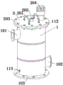
The labels in the figure are: a cylinder body 1; a water inlet pipe 101; a water outlet pipe 102; a base 103; a partition 104; a sedimentation tank 105; a U-shaped tube 106; activated carbon 107; a screen 108; a filter element 109; a positioning ring 110; a shoe 111; a flange plate 112; a blow-off pipe 113; a flange cover 2; a handle 201; an exhaust pipe 202; a bolt 203; an electric motor 204; a screw 205.
Detailed Description
In order to make the purpose, technical features and technical effects of the technical solution of the present invention clearer, the drawings of the embodiments of the present invention are combined together, and the example solution of the embodiments of the present invention is clearly and completely described.
Referring to fig. 1 to 5, the present application is an industrial sewage filtering apparatus, including a cylinder 1 and a flange cover 2, wherein the flange cover 2 is located right above the cylinder 1, a flange plate 112 is welded on the upper surface of the cylinder 1, the lower surface of the cylinder body 1 is welded with a base 103, a water inlet pipe 101 communicated with the inside of the upper part of the left side of the outer wall of the cylinder body 1 is arranged, a water outlet pipe 102 is arranged below the right side of the outer wall of the cylinder body 1, the water inlet pipe 101 and the water outlet pipe 102 penetrate into the cylinder body 1, two partition plates 104 which are distributed at equal intervals are embedded in the inner wall of the cylinder body 1, a sedimentation tank 105 is arranged in the middle of the upper surface of the partition plate 104 on the upper side, the left end of the sedimentation tank 105 is connected and communicated with the right end of the water inlet pipe 101, a sewage discharge pipe 113 communicated with the tail part of the filter element 109 is arranged below the inside of the cylinder body 1, the head end of the sewage discharge pipe 113 is inserted into the right side of the filter element 109, and the tail end of the sewage discharge pipe 113 penetrates through the outer wall of the left side of the cylinder body 1 and is communicated with the outside;
two symmetrically distributed handles 201 are welded on the left side and the right side of the upper surface of the flange cover 2, a circle of bolts 203 which are arranged at equal intervals are connected on the outer side of the upper surface of the flange cover 2 in a threaded mode, the flange cover 2 is fixedly connected with the flange plate 112 through a plurality of bolts 203, the middle of the upper surface of the flange cover 2 is connected with an exhaust pipe 202, the exhaust pipe 202 is located between the two handles 201, the lower end of the exhaust pipe 202 penetrates into the flange cover 2, the exhaust pipe 202 is inserted into the upper surface of the sedimentation tank 105 and is communicated with the interior of the sedimentation tank, a motor 204 which is arranged downwards is fixedly installed on the right side of the upper surface of the flange cover 2, and the motor 204 is located on the right side of the handle 201 on the right side;
a U-shaped pipe 106 is fixedly arranged between the two clapboards 104, the upper end of the right side of the U-shaped pipe 106 penetrates through the upper surface of the clapboard 104 on the upper side, the upper end of the right side of the U-shaped pipe 106 is communicated with the sedimentation tank 105, the bent part of the lower part inside the U-shaped pipe 106 is fixedly provided with a bottom support 111, activated carbon 107 is arranged in the bottom support 111, four filter screens 108 are arranged in the middle of the inner wall of the U-shaped pipe 106, the upper and lower surfaces of the filter screens 108 are respectively provided with a positioning ring 110, the filter screens 108 are detachably connected to the middle of the inner wall of the U-shaped pipe 106 through the positioning rings 110, the lower end of the left side of the U-shaped pipe 106 penetrates through the lower surface of the clapboard 104 on the lower side, the lower end of the left side of the U-shaped pipe 106 is connected and communicated with the left end of the water outlet pipe 102, a filter element 109 is detachably connected between the lower ends of the left side of the U-shaped pipe 106 and the outer wall of the positioning rings 110, mutually matched threads are arranged on the inner wall of the U-shaped pipe 106, the four filter screens 108 are sequentially increased from right to left, the interior of the filter element 109 is made by high-density packaging of hollow fiber membrane silk materials, the lower end of the motor 204 is connected with a screw 205 in a transmission way, and the lower end of the screw 205 extends into the upper end of the right side of the U-shaped pipe 106;
specifically, the user connects the water inlet pipe, the water outlet pipe 102 and the sewage discharge pipe 113 with the external pipe, then starts the motor 204, at this time, the sewage enters from the water inlet pipe and flows into the sedimentation tank 105, the exhaust pipe 202 is used for maintaining the air pressure in the sedimentation tank 105 to facilitate smooth circulation of the water flow, and the user can put a flocculating agent into the sedimentation tank 105 through the exhaust pipe 202 as a means for strengthening solid-liquid separation to make the solid impurities in the sewage preliminarily precipitate, the sedimentation tank 105 is located above the inside of the cylinder 1 and is closer to the flange cover 2, the user only needs to open the flange cover 2 and then detach the sedimentation tank 105, it is very convenient to clean the stains at the bottom of the sedimentation tank 105, then the water flow flows into the U-shaped pipe 106 from the upper side of the right side of the U-shaped pipe 106, because the motor 204 drives the screw 205 to rotate ceaselessly in the water flow, the flow speed of the water flow is greatly accelerated, the filtering speed is also accelerated, and the distribution of the impurities in the water flow is more uniform, the water flow is convenient for subsequent filtration, the water flow sequentially passes through the activated carbon 107 and the four filter screens 108, insoluble impurities in the water flow are sequentially filtered by the filter screens 108 from large to small due to the sequential increase of the filter density of the four filter screens 108, so that the impurities are filtered more thoroughly, the filter pressure born by each filter screen 108 is smaller, the service life of each filter screen 108 is prolonged, the impurities filtered by the filter screens 108 fall into the activated carbon 107 to be adsorbed due to the microporous surface of the activated carbon 107, the residual impurities in the filter screens 108 are greatly reduced, and the time for replacing and cleaning the filter screens 108 in large quantity is saved, so that the continuous operation efficiency of the filter device is greatly increased, the filter stroke is greatly increased due to the design of the U-shaped pipe 106, the filter time of the sewage in the U-shaped pipe 106 is longer, and the filter effect is greatly improved;
at this moment, the insoluble impurities inside the sewage through multilayer filtration have been basically filtered and completed, then water flow enters the filter element 109 to be filtered, because the filter element 109 is internally made by the high-density packaging of hollow fiber membrane silk material, the filter fineness is higher and the interception volume is greater, the dissolved impurities in the water flow are discharged from the blow-off pipe 113 after being filtered by the filter element 109, and clean water flows out from the water outlet pipe 102, the filter efficiency of the dissolved impurities is further improved, the water flow is cleaner, the installation of the industrial sewage filtering device is simpler, the applicability is very wide, the industrial sewage suitable for various types is filtered, the insoluble impurities in the water and the dissolved impurities can be completely filtered, and the filter effect is better.
In the present specification, each embodiment is described with emphasis on differences from other embodiments, and the same or similar parts between the embodiments may be referred to each other.
Unless otherwise defined, technical or scientific terms used in the present embodiments should have the ordinary meaning as understood by those having ordinary skill in the art to which the present invention belongs. Exemplary embodiments of the present invention have been described in detail with reference to the preferred embodiments, however, it will be understood by those skilled in the art that various modifications and changes may be made to the above specific embodiments without departing from the scope of the present invention, and various combinations of the technical features and structures of the present invention may be implemented without departing from the scope of the present invention, which is defined by the appended claims.
Claims (6)
1. The utility model provides an industrial sewage filter equipment, includes barrel (1) and flange lid (2), flange lid (2) are located directly over barrel (1), its characterized in that:
the water purifier is characterized in that a flange plate (112) is welded on the upper surface of the barrel body (1), a base (103) is welded on the lower surface of the barrel body (1), a water inlet pipe (101) communicated with the interior of the barrel body (1) is arranged above the left side of the outer wall of the barrel body (1), a water outlet pipe (102) is arranged below the right side of the outer wall of the barrel body (1), the water inlet pipe (101) and the water outlet pipe (102) penetrate through the interior of the barrel body (1), two partition plates (104) distributed at equal intervals are embedded in the inner wall of the barrel body (1), a sedimentation tank (105) is arranged in the middle of the upper surface of the partition plate (104) on the upper side, and the left end of the sedimentation tank (105) is connected and communicated with the right end of the water inlet pipe (101);
the left side and the right side of the upper surface of the flange cover (2) are welded with two symmetrically distributed handles (201), a circle of bolts (203) which are arranged at equal intervals are connected to the outer side of the upper surface of the flange cover (2) in a threaded mode, the flange cover (2) is fixedly connected with the flange plate (112) through a plurality of bolts (203), an exhaust pipe (202) is connected to the middle of the upper surface of the flange cover (2), the exhaust pipe (202) is located between the two handles (201), the lower end of the exhaust pipe (202) penetrates into the flange cover (2), the exhaust pipe (202) is inserted into the upper surface of the sedimentation tank (105) and communicated with the interior of the sedimentation tank, a motor (204) which is arranged downwards is fixedly installed on the right side of the upper surface of the flange cover (2), and the motor (204) is located on the right side of the handle (201) on the right side;
a U-shaped pipe (106) is fixedly installed between the two partition plates (104), the upper end of the right side of the U-shaped pipe (106) penetrates through the upper surface of the partition plate (104) on the upper side, the upper end of the right side of the U-shaped pipe (106) is communicated with the sedimentation tank (105), bending parts below the inner part of the U-shaped pipe (106) are fixedly provided with bottom supports (111), active carbon (107) is arranged in the bottom supports (111), four filter screens (108) are arranged in the middle of the inner wall of the U-shaped pipe (106), positioning rings (110) are arranged on the upper surface and the lower surface of each filter screen (108), the filter screens (108) are detachably connected to the middle of the inner wall of the U-shaped pipe (106) through the positioning rings (110), the lower end of the left side of the U-shaped pipe (106) penetrates through the lower surface of the partition plate (104), and the lower end of the left side of the U-shaped pipe (106) is connected and communicated with the left end of the water outlet pipe (102), a filter element (109) is detachably connected between the water outlet pipe (102) and the lower end of the left side of the U-shaped pipe (106).
2. The industrial sewage filtering apparatus according to claim 1, wherein: the inner wall of the U-shaped pipe (106) and the outer wall of the positioning ring (110) are provided with threads which are matched with each other.
3. The industrial sewage filtering apparatus according to claim 1, wherein: the filtering densities of the four filter screens (108) are increased from right to left in sequence.
4. The industrial sewage filtering apparatus according to claim 1, wherein: the interior of the filter element (109) is made of hollow fiber membrane silk materials in a high-density packaging mode.
5. The industrial sewage filtering apparatus according to claim 1, wherein: the lower end of the motor (204) is in transmission connection with a screw rod (205), and the lower end of the screw rod (205) extends into the upper end of the right side of the U-shaped pipe (106).
6. The industrial sewage filtering apparatus according to claim 1, wherein: the utility model discloses a filter cartridge, including barrel (1), barrel (1) inside below be equipped with communicating blow off pipe (113) of filter core (109) afterbody, the head end of blow off pipe (113) peg graft in the right side of filter core (109), just blow off pipe (113) tail end runs through out barrel (1) left side outer wall and communicates with each other with the external world.
Priority Applications (1)
| Application Number | Priority Date | Filing Date | Title |
|---|---|---|---|
| CN202023074559.9U CN214936575U (en) | 2020-12-19 | 2020-12-19 | Industrial sewage filtering device |
Applications Claiming Priority (1)
| Application Number | Priority Date | Filing Date | Title |
|---|---|---|---|
| CN202023074559.9U CN214936575U (en) | 2020-12-19 | 2020-12-19 | Industrial sewage filtering device |
Publications (1)
| Publication Number | Publication Date |
|---|---|
| CN214936575U true CN214936575U (en) | 2021-11-30 |
Family
ID=79114314
Family Applications (1)
| Application Number | Title | Priority Date | Filing Date |
|---|---|---|---|
| CN202023074559.9U Active CN214936575U (en) | 2020-12-19 | 2020-12-19 | Industrial sewage filtering device |
Country Status (1)
| Country | Link |
|---|---|
| CN (1) | CN214936575U (en) |
-
2020
- 2020-12-19 CN CN202023074559.9U patent/CN214936575U/en active Active
Similar Documents
| Publication | Publication Date | Title |
|---|---|---|
| CN108675528A (en) | A kind of sewage treatment equipment | |
| CN100486681C (en) | Outer installation type gas lift circulation membrane splitter | |
| CN214031934U (en) | Sand-water separation device of industrial sewage pump station | |
| CN219194767U (en) | Tail water treatment integrated equipment for mariculture | |
| CN214936575U (en) | Industrial sewage filtering device | |
| CN108083480A (en) | Integrated Emergency management device is denitrogenated in a kind of ceramic membrane separation decarburization | |
| CN211688511U (en) | Sewage purification device | |
| CN216092640U (en) | Efficient and energy-saving sewage treatment integrated equipment | |
| CN113068651B (en) | High-density water quality purification system for crayfish breeding and method thereof | |
| CN208747850U (en) | One kind is for cleaning papermaking processing sewage disposal system | |
| CN209049884U (en) | A kind of device of bioleaching combination organic acid removal heavy metal in soil | |
| CN208799970U (en) | A kind of monoammonium phosphate purification processes device | |
| CN209934207U (en) | Novel reclaimed water recycling treatment device | |
| CN111825282A (en) | Automatic aeration biological filter | |
| CN206457305U (en) | A kind of BAF and its washed-out sand mechanism | |
| CN217188234U (en) | Dense water treatment facilities of industry sewage reverse osmosis membrane | |
| CN219929724U (en) | Reverse osmosis filter device for pure water manufacture | |
| CN217139431U (en) | Filter machine | |
| CN214031832U (en) | Aeration-membrane-free solid-liquid separation device | |
| CN212662817U (en) | Rotary disc micro-filter | |
| CN214495901U (en) | A waste liquid recovery unit for electroplating slagging-off | |
| CN214192813U (en) | Efficient printing and dyeing sewage treatment plant | |
| CN217909513U (en) | Sewage treatment equipment with gas collection function | |
| CN221131147U (en) | Fine particle recovery device in slime water | |
| CN217015593U (en) | Combined full-automatic intelligent filtering device |
Legal Events
| Date | Code | Title | Description |
|---|---|---|---|
| GR01 | Patent grant | ||
| GR01 | Patent grant | ||
| CP01 | Change in the name or title of a patent holder | ||
| CP01 | Change in the name or title of a patent holder |
Address after: 710000 room 31602-a3, floor 16, unit 3, building 1, Hesheng Jingguang Center, No. 11, Tangyan Road, high tech Zone, Xi'an, Shaanxi Patentee after: Shaanxi Yijie Boshun Environmental Protection Technology Co.,Ltd. Address before: 710000 room 31602-a3, floor 16, unit 3, building 1, Hesheng Jingguang Center, No. 11, Tangyan Road, high tech Zone, Xi'an, Shaanxi Patentee before: Shaanxi boshunzhiyue Environmental Technology Co.,Ltd. |