CN214911342U - Lateral ventricle drainage bottle height fixing frame - Google Patents
Lateral ventricle drainage bottle height fixing frame Download PDFInfo
- Publication number
- CN214911342U CN214911342U CN202121975976.2U CN202121975976U CN214911342U CN 214911342 U CN214911342 U CN 214911342U CN 202121975976 U CN202121975976 U CN 202121975976U CN 214911342 U CN214911342 U CN 214911342U
- Authority
- CN
- China
- Prior art keywords
- auxiliary rod
- rod
- drainage bottle
- column
- knob
- Prior art date
- Legal status (The legal status is an assumption and is not a legal conclusion. Google has not performed a legal analysis and makes no representation as to the accuracy of the status listed.)
- Active
Links
Images

Landscapes
- External Artificial Organs (AREA)
- Medical Preparation Storing Or Oral Administration Devices (AREA)
Abstract
The utility model belongs to the field of medical equipment, in particular to a lateral ventricle drainage bottle height fixing frame, which comprises a bottom fixing column, wherein the bottom fixing column is connected with a first threaded rod, and the first threaded rod is connected with a main rod through threads; the left side both ends of mobile jib are provided with the mobile jib side hook, the mobile jib links to each other with second screw thread post, second screw thread post passes through the screw thread and links to each other with top concatenation post, the right side of top concatenation post is provided with the infusion couple, be provided with the auxiliary rod on the mobile jib, the drainage bottle can be hung to the auxiliary rod, and can also adjust and measure the height that the drainage bottle hung, make progress or the downstream along the mobile jib with the auxiliary rod, just can make progress or the down regulation with the auxiliary rod with the height of hanging the drainage bottle on the auxiliary rod side hook, then clockwise turning and screwing up the fixed knob of auxiliary rod, just can fix the height after the drainage bottle is adjusted, traditional artifical measurement and the inaccurate condition of prediction drainage bottle height have been avoided, the risk or the danger of patient side ventricle drainage work have been reduced, the effectual practicality that provides the apparatus and use.
Description
Technical Field
The utility model relates to the field of medical equipment, in particular to a lateral ventricle drainage bottle height fixing frame.
Background
In clinical work, a large number of patients with ventricular drainage tubes are left in cerebral surgery, the drainage height of a drainage bottle has an extremely important influence on cranial pressure and directly influences the treatment effect of the patients, and the life of the patients is slightly carelessly endangered, such as (1) over 20cm can cause unsmooth drainage and can not reduce intracranial pressure, (2) under 10cm, the drainage can be caused to be unsmooth, the drainage is too fast, the intracranial pressure can be reduced, the brain displacement is caused, in the nursing process, the measured height and the 0 point of the patient can be frequently reevaluated due to the change of the body position, the conventional flexible ruler and personal sensory measurement is frequently used at the 0 point in the clinical work, the randomness is strong, and the accuracy of the 0 point is determined by human errors, so that the data are not strict. (3) Some patients need to do puncture catheterization on ventricles at two sides, the pipelines are many and messy, left and right drainage tubes are not easy to distinguish, the pipelines are easy to fall off, the drainage control amount is limited, the time for nurses to change shifts to work for tidying up is long, and the working quality and the working mood are affected.
The traditional appliance for supporting or hanging up the drainage bottle has complex and tedious height adjustment and long time, the nurse shift time is prolonged, and the installation and the disassembly are inconvenient, and the traditional appliance only has a single direction or a single hook, so that the problems of more and messy pipelines of the hung drainage bottle and the like cannot be improved; the height of the adjusted drainage bottle is relatively fixed, so that the drainage bottle can not be simply, conveniently and effectively adjusted when the head of the bed is raised or lowered, the apparatus is not perfect enough, and the social requirements are difficult to meet.
Therefore, how to design the lateral ventricle drainage bottle height fixing frame becomes a problem which needs to be solved currently.
SUMMERY OF THE UTILITY MODEL
An object of the utility model is to provide a side ventricle drainage bottle height mount, in order to solve above it is loaded down with trivial details, not convenient to detach, installation and height measurement's weak point to provide altitude mixture control among the background art.
In order to achieve the above object, the utility model provides a following technical scheme: the lateral ventricle drainage bottle height fixing frame comprises a main rod and an auxiliary rod for hanging the drainage bottle, wherein the bottom of the main rod is provided with a bottom fixing column for connecting with a preset hole of a sickbed, and the auxiliary rod is sleeved on the main rod and can slide along the main rod; the bottom end fixing column is connected with the first threaded rod, and the main rod is connected with the first threaded rod through threads; two ends of the bottom of the main rod are oppositely provided with main rod side hooks for hanging a drainage bag, the bottom of the main rod is provided with a second threaded column for splicing, and the second threaded column is connected with the middle splicing column through threads; the top of the middle splicing column is provided with a third threaded column for splicing, and the third threaded column is connected with the top splicing column through threads; the top of the top splicing column is oppositely provided with an infusion hook for hanging an infusion bottle; an auxiliary rod fixing knob is arranged at the top of the rear end of the auxiliary rod and is connected with the auxiliary rod through threads, and the end part of the auxiliary rod fixing knob can penetrate into the auxiliary rod and is abutted against the main rod; the tops of the two sides of the auxiliary rod are oppositely provided with auxiliary rod side hooks for hanging drainage bottles; a clamping threaded hole is formed in the auxiliary rod, and a clamping knob is connected to the clamping threaded hole in a threaded mode; the clamping knob is rotatably provided with a graduated scale, the graduated scale can rotate around the clamping knob and is fixed on the auxiliary rod through the clamping knob when the clamping knob is screwed, a second graduated scale is sleeved in the graduated scale, and the second graduated scale can slide in the graduated scale along the length direction of the graduated scale; the last rotation of chucking knob is provided with the level bar, and the level bar can rotate around the chucking knob and fix on vice pole through the chucking knob when the chucking knob is screwed, the level bar is located the scale and keeps away from one side of vice pole.
Preferably, a clamping groove for placing an identification card is arranged on the auxiliary rod.
Preferably, level air bubbles for performing horizontal measurement are arranged on two sides of the top end of the level bar, and the level air bubbles can move on the level bar.
Preferably, the main rod has a cylindrical shape.
Preferably, the main rod is provided with scales for measurement, and the scales extend along the length direction of the main rod and are used for measuring the height between the auxiliary rod and the bed board.
Preferably, the shape of the auxiliary rod is a cuboid.
Preferably, a cylindrical cavity is arranged in the middle of the auxiliary rod.
Compared with the prior art, the beneficial effects of the utility model are that:
1. this high mount of side ventricle drainage bottle, mobile jib can support the mount, and convenient to detach and installation fall into four little parts with top concatenation post, middle concatenation post, mobile jib and bottom fixed column and place the storage, and the storage of accomodating of the apparatus of being convenient for is effectual the convenience of mount installation and dismantlement that provides.
2. This side ventricle drainage bottle high mount, the drainage bottle can be hung to the auxiliary rod, and can also adjust and measure the height that the drainage bottle hung to avoided traditional artifical measurement and estimated drainage bottle height and unsafe condition, reduced the risk or the danger of patient side ventricle drainage work, but the practicality of effectual provision apparatus use.
Drawings
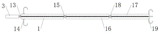
Fig. 1 is a schematic view of the overall structure of the present invention;
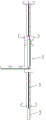
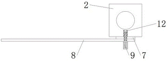
FIG. 2 is a schematic view of the structure of the auxiliary rod of the present invention;
FIG. 3 is a cross-sectional view taken along line A-A of the present invention;
fig. 4 is a schematic structural view of the main rod of the present invention when it is horizontally placed.
In the figure: 1. a main rod; 2. an auxiliary rod; 3. a bottom end fixing column; 4. a card slot; 5. a side hook of the auxiliary rod; 6. the auxiliary rod fixes the knob; 7. a graduated scale; 8. a level bar; 9. clamping the knob; 10. leveling air bubbles; 11. a second scale; 12. clamping the threaded hole; 13. a first threaded rod; 14. a main rod side hook; 15. a second threaded post; 16. a middle splicing column; 17. a top splice column; 18. a third threaded post; 19. an infusion hook.
Detailed Description
The technical solution in the embodiment of the present invention will be described clearly and completely with reference to the accompanying drawings in the embodiment of the present invention, and obviously, the described embodiment is only a part of the embodiments of the present invention, rather than all embodiments, and all other embodiments obtained by a person of ordinary skill in the art without creative work belong to the protection scope of the present invention based on the embodiments of the present invention.
In the description of the present invention, it is to be understood that the terms "center", "longitudinal", "lateral", "length", "width", "thickness", "upper", "lower", "front", "rear", "left", "right", "vertical", "horizontal", "top", "bottom", "inner", "outer", "clockwise", "counterclockwise", and the like, indicate orientations or positional relationships based on the orientations or positional relationships shown in the drawings, and are used only for convenience of description and for simplicity of description, and do not indicate or imply that the equipment or element referred to must have a particular orientation, be constructed and operated in a particular orientation, and therefore should not be construed as limiting the present invention.
Furthermore, the terms "first", "second" and "first" are used for descriptive purposes only and are not to be construed as indicating or implying relative importance or implicit indication of the number of technical features indicated, whereby features defined as "first", "second" and "first" may or may not explicitly include one or more of such features, and in the description of the invention "plurality" means two or more unless explicitly specifically defined otherwise.
In the first embodiment, please refer to fig. 1-4, the present invention provides a technical solution: the lateral ventricle drainage bottle height fixing frame comprises a main rod 1 and an auxiliary rod 2 for hanging the drainage bottle, wherein the bottom of the main rod 1 is provided with a bottom fixing column 3 for connecting with a preset hole of a sickbed, and the auxiliary rod 2 is sleeved on the main rod 1 and can slide along the main rod 1; the bottom end fixing column 3 is connected with a first threaded rod 13, and the main rod 1 is connected with the first threaded rod 13 through threads; two ends of the bottom of the main rod 1 are oppositely provided with main rod side hooks 14 used for hanging a drainage bag, the bottom of the main rod 1 is provided with a second threaded column 15 used for splicing, and the second threaded column 15 is connected with a middle splicing column 16 through threads; the top of the middle splicing column 16 is provided with a third threaded column 18 for splicing, and the third threaded column 18 is connected with a top splicing column 17 through threads; the top of the top splicing column 17 is oppositely provided with an infusion hook 19 for hanging an infusion bottle; an auxiliary rod fixing knob 6 is arranged at the top of the rear end of the auxiliary rod 2, the auxiliary rod fixing knob 6 is connected with the auxiliary rod 2 through threads, and the end part of the auxiliary rod fixing knob 6 can penetrate into the auxiliary rod 2 to be abutted against the main rod 1; the tops of the two sides of the auxiliary rod 2 are oppositely provided with auxiliary rod side hooks 5 for hanging drainage bottles; a clamping threaded hole 12 is formed in the auxiliary rod 2, and a clamping knob 9 is connected to the clamping threaded hole 12 in a threaded mode; a graduated scale 7 is rotatably arranged on the clamping knob 9, the graduated scale 7 can rotate around the clamping knob 9 and is fixed on the auxiliary rod 2 through the clamping knob 9 when the clamping knob 9 is screwed tightly, a second graduated scale 11 is sleeved in the graduated scale 7, and the second graduated scale 11 can slide in the graduated scale 7 along the length direction of the graduated scale 7; rotation is provided with level bar 8 on chucking knob 9, and level bar 8 can rotate and fix on vice pole 2 through chucking knob 9 when chucking knob 9 is screwed around chucking knob 9, and level bar 8 is located scale 7 and keeps away from one side of vice pole 2, is provided with draw-in groove 4 that is used for placing the identification card on vice pole 2.
Preferably, the top both sides of level bar 8 are provided with the level bubble 10 that is used for carrying out horizontal measurement, level bubble 10 can move on level bar 8, when the patient carries out side ventricle drainage work, the level that the mount was placed needs to be kept, the mount need be installed on bed board or bedstead when using, when using level bar 8, need keep level bar 8 and mobile jib 1 or auxiliary rod 2 perpendicular, look again the level bubble 10 position in level bar 8, just reduce the height of which direction to which position skew at level bubble 10, until level bubble 10 in level bar 8 is located the intermediate position, thereby accomplish the horizontal measurement of level bar 8 and the horizontal position control of mount.
Preferably, the appearance of the main rod 1 is cylindrical, the main rod 1 is provided with scales for measurement, the scales extend along the length direction of the main rod 1 and are used for measuring the height of the auxiliary rod 2 from a bed board, the main rod 1 can support a fixing frame and is convenient to detach and install, when the fixing frame is used, the main rod 1 is installed firstly, a first threaded rod 13 connected to a bottom fixing column 3 is embedded into the main rod 1 and is screwed up by clockwise rotation, a second threaded column 15 connected to the main rod 1 is embedded into a middle splicing column 16 and is screwed up by clockwise rotation, the top end of the middle splicing column 16 penetrates through a cylindrical cavity at the middle position of the auxiliary rod 2 from bottom to top, a third threaded column 18 connected to the middle splicing column 16 is embedded into a top splicing column 17 and is screwed up by clockwise rotation, the splicing of the main rod 1 is completed, a hole for inserting an infusion rod is arranged on a sickbed, then the bottom fixing column 3 arranged at the bottom of the spliced main rod 1 is embedded into a hole arranged on the sickbed from top to bottom, thereby completing the installation and fixation of the main rod 1, the main rod side hook 14 arranged on the main rod 1 can hang a drainage bag, the infusion hook 19 arranged on the main rod 1 can hang an infusion bottle, the fixing frame can be used for hanging an infusion bottle used during infusion besides meeting the work of lateral ventricle drainage, and when the fixing frame is not used, the main rod 1 can be drawn out from the hole arranged on the sickbed, the top splicing column 17, the middle splicing column 16 and the bottom fixing column 3 are rotated anticlockwise and unscrewed for disassembly, thereby place the storage with top concatenation post 17, middle concatenation post 16, mobile jib 1 and bottom fixed column 3 divide into four little parts, the storage of accomodating of the apparatus of being convenient for, the effectual convenience that provides mount installation and dismantlement.
Preferably, the auxiliary rod 2 is a cuboid, a cylindrical cavity is arranged in the middle of the auxiliary rod 2, the auxiliary rod 2 can be used for hanging a drainage bottle and can also be used for adjusting and measuring the hanging height of the drainage bottle, the auxiliary rod 2 is arranged on the main rod 1, when the auxiliary rod 2 is used, a lateral ventricle drainage bottle can be hung on an auxiliary rod side hook 5 arranged on the auxiliary rod 2, a marking card can be placed in a clamping groove 4 arranged on the auxiliary rod 2, when the hanging height of the lateral ventricle drainage bottle is measured, the clamping knob 9 can be rotated anticlockwise and unscrewed, the graduated scale 7 can be rotated, the telescopic second graduated scale 11 is arranged in the graduated scale 7, so that the measurable length is improved, when the graduated scale 7 is used for measurement, the graduated scale 7 is rotated clockwise or clockwise by one hundred eighty degrees by taking the clamping knob 9 as a center, so that the length from the clamping knob 9 to the starting point of the height is measured anticlockwise, then the graduated scale 7 is rotated clockwise or anticlockwise by one hundred eighty degrees, the height of the clamping knob 9 reaching the suspended lateral ventricle drainage bottle can be measured, the two measured lengths are added, the height from the initial point to the lateral ventricle drainage bottle can be obtained, after the measurement is finished, the graduated scale 7 and the horizontal scale 8 are rotated to the same direction and are overlapped, then the clamping knob 9 is rotated clockwise and screwed down, the horizontal scale 8 and the graduated scale 7 after being stored can be fixed, in addition, when the height of the lateral ventricle drainage bottle is adjusted, the auxiliary rod fixing knob 6 can be rotated anticlockwise and unscrewed, the auxiliary rod 2 moves upwards or downwards along the main rod 1, the heights of the auxiliary rod 2 and the drainage bottle hung on the auxiliary rod side hook 5 can be adjusted upwards or downwards, then the auxiliary rod fixing knob 6 is rotated clockwise and screwed down, the height of the drainage bottle after being adjusted can be fixed, thereby avoided traditional manual measurement and pre-estimate drainage bottle height and the unsafe condition, reduced the risk or the danger of patient's side ventricle drainage work, but the practicality of instrument use is effectively provided.
The working principle is as follows: firstly, whether a horizontal ruler 8 can be normally used is checked, leveling air bubbles 10 for performing horizontal measurement are arranged on two sides of the top end of the horizontal ruler 8, the leveling air bubbles 10 can move on the horizontal ruler 8, when a patient conducts lateral ventricle drainage work, the level of a fixing frame needs to be kept, the fixing frame needs to be installed on a bed board or a bed frame when in use, when the horizontal ruler 8 is used, the horizontal ruler 8 needs to be kept vertical to a main rod 1 or an auxiliary rod 2, then the position of the leveling air bubbles 10 in the horizontal ruler 8 is observed, and the height in which direction is reduced when the leveling air bubbles 10 deviate to which position until the leveling air bubbles 10 in the horizontal ruler 8 are located at the middle position, so that the horizontal measurement of the horizontal ruler 8 and the horizontal position adjustment of the fixing frame are completed;
then, the fixing frame is supported by the main rod 1, the main rod 1 is cylindrical, the main rod 1 is provided with scales for measurement, the scales extend along the length direction of the main rod 1 and are used for measuring the height of the auxiliary rod 2 from the bed board, the main rod 1 can support the fixing frame and is convenient to disassemble and install, when the fixing frame is used, the main rod 1 is firstly installed, a first threaded rod 13 connected with a bottom fixing column 3 is embedded into the main rod 1 and is screwed up in a clockwise rotating mode, a second threaded column 15 connected with the main rod 1 is embedded into a middle splicing column 16 and is screwed up in a clockwise rotating mode, the top end of the middle splicing column 16 penetrates through a cylindrical cavity in the middle of the auxiliary rod 2 from bottom to top, then a third threaded column 18 connected with the middle splicing column 16 is embedded into a top splicing column 17 and is screwed up in a clockwise rotating mode, the splicing of the main rod 1 is completed, a hole for inserting an infusion rod is formed in a hospital bed, then the bottom fixing column 3 arranged at the bottom of the spliced main rod 1 is embedded into a hole arranged on the sickbed from top to bottom, thereby completing the installation and fixation of the main rod 1, the main rod side hook 14 arranged on the main rod 1 can hang a drainage bag, the infusion hook 19 arranged on the main rod 1 can hang an infusion bottle, the fixing frame can be used for hanging an infusion bottle used during infusion besides meeting the work of lateral ventricle drainage, and when the fixing frame is not used, the main rod 1 can be drawn out from the hole arranged on the sickbed, the top splicing column 17, the middle splicing column 16 and the bottom fixing column 3 are rotated anticlockwise and unscrewed for disassembly, therefore, the top splicing column 17, the middle splicing column 16, the main rod 1 and the bottom fixing column 3 are divided into four small components for storage, so that the storage and the preservation of instruments are facilitated, and the convenience for mounting and dismounting the fixing frame is effectively provided;
finally, the drainage bottle is hung through the auxiliary rod 2, the appearance of the auxiliary rod 2 is set to be a cuboid, a cylindrical cavity is arranged in the middle in the auxiliary rod 2, the auxiliary rod 2 can hang the drainage bottle and can also adjust and measure the hanging height of the drainage bottle, the auxiliary rod 2 is arranged on the main rod 1, when the auxiliary rod 2 is used, the lateral ventricle drainage bottle can be hung on the auxiliary rod side hook 5 arranged on the auxiliary rod 2, the clamp groove 4 arranged on the auxiliary rod 2 can be used for placing an identification card, when the hanging height of the lateral ventricle drainage bottle is measured, the clamping knob 9 can be rotated anticlockwise and unscrewed to enable the graduated scale 7 to rotate, the telescopic second graduated scale 11 is arranged in the graduated scale 7 to improve the length capable of being measured, when the graduated scale 7 is used for measurement, the graduated scale 7 is rotated clockwise or anticlockwise by eighty degrees with the clamping knob 9 as the center, so that the length from the clamping knob 9 to the initial point of the height is measured, then the graduated scale 7 is rotated clockwise or anticlockwise by one hundred eighty degrees, the height of the clamping knob 9 reaching the suspended lateral ventricle drainage bottle can be measured, the two measured lengths are added, the height from the initial point to the lateral ventricle drainage bottle can be obtained, after the measurement is finished, the graduated scale 7 and the horizontal scale 8 are rotated to the same direction and are overlapped, then the clamping knob 9 is rotated clockwise and screwed down, the horizontal scale 8 and the graduated scale 7 after being stored can be fixed, in addition, when the height of the lateral ventricle drainage bottle is adjusted, the auxiliary rod fixing knob 6 can be rotated anticlockwise and unscrewed, the auxiliary rod 2 moves upwards or downwards along the main rod 1, the heights of the auxiliary rod 2 and the drainage bottle hung on the auxiliary rod side hook 5 can be adjusted upwards or downwards, then the auxiliary rod fixing knob 6 is rotated clockwise and screwed down, the height of the drainage bottle after being adjusted can be fixed, thereby avoided traditional manual measurement and estimated drainage bottle height and the unsafe condition, reduced the risk or the danger of patient's side ventricle drainage work, but the practicality of apparatus use is effectively provided, this is the theory of operation of this side ventricle drainage bottle height mount.
Although embodiments of the present invention have been shown and described, it will be appreciated by those skilled in the art that changes, modifications, substitutions and alterations can be made in these embodiments without departing from the principles and spirit of the invention, the scope of which is defined in the appended claims and their equivalents.
Claims (7)
1. High mount of side ventricle drainage bottle, including mobile jib (1) and vice pole (2) of hanging the drainage bottle, its characterized in that: the bottom of the main rod (1) is provided with a bottom fixing column (3) used for being connected with a preset hole of a sickbed, and the auxiliary rod (2) is sleeved on the main rod (1) and can slide along the main rod (1); the bottom end fixing column (3) is connected with the first threaded rod (13), and the main rod (1) is connected with the first threaded rod (13) through threads; two ends of the bottom of the main rod (1) are oppositely provided with main rod side hooks (14) for hanging a drainage bag, the bottom of the main rod (1) is provided with a second threaded column (15) for splicing, and the second threaded column (15) is connected with a middle splicing column (16) through threads; the top of the middle splicing column (16) is provided with a third threaded column (18) for splicing, and the third threaded column (18) is connected with the top splicing column (17) through threads; the top of the top splicing column (17) is relatively provided with an infusion hook (19) for hanging an infusion bottle; an auxiliary rod fixing knob (6) is arranged at the top of the rear end of the auxiliary rod (2), the auxiliary rod fixing knob (6) is connected with the auxiliary rod (2) through threads, and the end part of the auxiliary rod fixing knob (6) can penetrate into the auxiliary rod (2) to be abutted against the main rod (1); the tops of the two sides of the auxiliary rod (2) are oppositely provided with auxiliary rod side hooks (5) for hanging drainage bottles; a clamping threaded hole (12) is formed in the auxiliary rod (2), and a clamping knob (9) is connected to the clamping threaded hole (12) in a threaded mode; the clamping knob (9) is rotatably provided with a graduated scale (7), the graduated scale (7) can rotate around the clamping knob (9) and is fixed on the auxiliary rod (2) through the clamping knob (9) when the clamping knob (9) is screwed, a second graduated scale (11) is sleeved in the graduated scale (7), and the second graduated scale (11) can slide in the graduated scale (7) along the length direction of the graduated scale (7); the upper rotating clamping knob (9) is provided with a horizontal ruler (8), the horizontal ruler (8) can rotate around the clamping knob (9) and is fixed on the auxiliary rod (2) through the clamping knob (9) when the clamping knob (9) is screwed, and the horizontal ruler (8) is located on one side, away from the auxiliary rod (2), of the graduated scale (7).
2. The lateral ventricle drainage bottle height mount of claim 1, wherein: and a clamping groove (4) for placing an identification card is arranged on the auxiliary rod (2).
3. The lateral ventricle drainage bottle height mount of claim 1, wherein: level bubble (10) that are used for carrying out the level measurement are provided with in the top both sides of spirit level (8), and level bubble (10) can move on spirit level (8).
4. The lateral ventricle drainage bottle height mount of claim 1, wherein: the shape of the main rod (1) is cylindrical.
5. The lateral ventricle drainage bottle height mount of claim 1, wherein: be provided with the scale that is used for measuring on mobile jib (1), the scale extends along the length direction of mobile jib (1) and is used for measuring the height of vice pole (2) apart from the bed board.
6. The lateral ventricle drainage bottle height mount of claim 1, wherein: the shape of the auxiliary rod (2) is a cuboid.
7. The lateral ventricle drainage bottle height mount of claim 1, wherein: the middle in the auxiliary rod (2) is provided with a cylindrical cavity.
Priority Applications (1)
| Application Number | Priority Date | Filing Date | Title |
|---|---|---|---|
| CN202121975976.2U CN214911342U (en) | 2021-08-23 | 2021-08-23 | Lateral ventricle drainage bottle height fixing frame |
Applications Claiming Priority (1)
| Application Number | Priority Date | Filing Date | Title |
|---|---|---|---|
| CN202121975976.2U CN214911342U (en) | 2021-08-23 | 2021-08-23 | Lateral ventricle drainage bottle height fixing frame |
Publications (1)
| Publication Number | Publication Date |
|---|---|
| CN214911342U true CN214911342U (en) | 2021-11-30 |
Family
ID=79068664
Family Applications (1)
| Application Number | Title | Priority Date | Filing Date |
|---|---|---|---|
| CN202121975976.2U Active CN214911342U (en) | 2021-08-23 | 2021-08-23 | Lateral ventricle drainage bottle height fixing frame |
Country Status (1)
| Country | Link |
|---|---|
| CN (1) | CN214911342U (en) |
-
2021
- 2021-08-23 CN CN202121975976.2U patent/CN214911342U/en active Active
Similar Documents
| Publication | Publication Date | Title |
|---|---|---|
| CN214911342U (en) | Lateral ventricle drainage bottle height fixing frame | |
| CN215840860U (en) | Pressure-measuring venous transfusion rack | |
| CN208404550U (en) | central venous pressure measuring device | |
| CN203828912U (en) | Central venous pressure measuring scale | |
| CN103816583B (en) | A kind of can the drip stand of measuring center venous pressure | |
| CN213911726U (en) | Multifunctional infusion support capable of measuring central venous pressure | |
| CN213698175U (en) | Drainage device auxiliary measuring device | |
| CN221711921U (en) | Central venous pressure measuring ruler | |
| CN206454093U (en) | A kind of drainage tube height-gauge | |
| CN103815887B (en) | Centre venous pressure measuring rule | |
| CN213191536U (en) | Bedside drainage fixed bolster | |
| CN215134766U (en) | Dual-purpose infusion support | |
| CN219539036U (en) | Suspension bracket for ventricular external drainage bottle | |
| CN215135618U (en) | Fixing and adjusting device for measuring height of craniocerebral drainage tube | |
| CN212466118U (en) | Ventricular puncture positioning instrument | |
| CN213667105U (en) | Ventricular external drainage bottle height adjuster | |
| CN203824473U (en) | Gauge for measuring height of external ventricular drainage pipe | |
| CN217645460U (en) | Infusion support and sickbed with infusion support | |
| CN215460607U (en) | Drainage tube fixer | |
| CN211962687U (en) | Adjustable ventricular drainage suspension fixing device | |
| CN202437101U (en) | A central venous pressure-measuring scale | |
| CN218484560U (en) | Cerebrospinal fluid pressure measurement and external drainage dual-purpose tube | |
| CN214434339U (en) | Rib retractor for thoracic surgeon | |
| CN217960973U (en) | Cerebrospinal fluid positioning and measuring device | |
| CN212369354U (en) | Device for measuring fixed height of ventricular drainage tube |
Legal Events
| Date | Code | Title | Description |
|---|---|---|---|
| GR01 | Patent grant | ||
| GR01 | Patent grant |