CN2148100Y - Automatic water supply controller - Google Patents
Automatic water supply controller Download PDFInfo
- Publication number
- CN2148100Y CN2148100Y CN 92245262 CN92245262U CN2148100Y CN 2148100 Y CN2148100 Y CN 2148100Y CN 92245262 CN92245262 CN 92245262 CN 92245262 U CN92245262 U CN 92245262U CN 2148100 Y CN2148100 Y CN 2148100Y
- Authority
- CN
- China
- Prior art keywords
- governor
- pressure
- triode
- water supply
- circuit
- Prior art date
- Legal status (The legal status is an assumption and is not a legal conclusion. Google has not performed a legal analysis and makes no representation as to the accuracy of the status listed.)
- Expired - Fee Related
Links
Images
Landscapes
- Control Of Positive-Displacement Pumps (AREA)
Abstract
The utility model provides an automatic water supply controller for controlling water supply under constant pressure. The automatic water supply controller is composed of a speed governor (2), an air circuit breaker (3), a fuse (4), a thermal relay (5), an inductance coil (6), buzzers (7), (8) installed in a vertical cabinet (1), a regulated power supply composed of two printed wiring boards and electronic elements thereof, an instantaneous stopping protecting circuit of the speed governor (2), a pressure variable-speed input circuit of the speed governor (2), a pressure control circuit of a constant-speed pump, a water level control circuit, and a frequency list (11), an ammeter (12), switches (13), (14), (15) and indicator lights (16), (17), (18), (19) on a fixed panel. The utility model has the advantages of energy saving, timely and reliable water supply, etc., and the utility model can automatically cut off the power supply to stop supplying water and give an alarm at the time of fault.
Description
The utility model relates to a kind of automatic constant-pressure control to supplying water.
Present speed governing water supply facilities generally all is provided with the standby constant speed pump of a cover by A.C. contactor control, puts into operation under water use peak or governor failure condition.Pressure is uncontrollable when adopting the independent continuous water supply of constant speed pump, easily causes pipeline leakage when hypertonia still continues feedwater, i.e. water wasting takes again.If adopt pressure controller to control, certainly will cause the A.C. contactor frequent movement, may burn out contact, and because the vibration of adhesive and release is increased accident rate.
Task of the present utility model provides a kind of energy, safe and reliable of both having saved, and water supply is carried out the self water feeding control device of constant voltage control.
Task of the present utility model is to combine and realize that it is by resistance R that its governor wink stops holding circuit by being installed in stopping holding circuit, governor pressure inverting input circuit, constant speed pump pressure control circuit and water-level control circuit in governor, air-break, fuse, thermal relay, inductance coil, buzzer and the voltage-stabilized power supply of being made up of the electronic device on the two bar printing wiring boards, governor wink and being fixed on frequency meter, ammeter, switch, indicator lamp on the panel in the vertical counter
1, capacitor C
2Get dividing potential drop time-delay input unijunction transistor T
1, unijunction transistor T
1The pulse signal of first base stage output is through triode BG
1Amplify series connection and insert relay J
1, and connect its normal opened contact J
1-1-J
1-3Its governor pressure inverting input circuit is by teletransmission pressure meter W
1The pressure-dependent voltage signal of sending is through resistance R
6, potentiometer W
2Enter triode BG
2Base stage is through triode BG
2, BG
3Two-stage is passed through resistance R after amplifying
11Send into the governor signal end.Its constant speed pump pressure control circuit is that the pressure controller normally closed contact is inserted triode BG
4Base stage is to control its conducting and to end triode BG
4Colelctor electrode through resistance R
13Signal is imported by unijunction transistor T
2With pulse transformer B
3The oscillation circuit formed of elementary winding, the controllable silicon SCR that respectively is in parallel by the direct control of the pulse signal of secondary windings again.And thermal relay normally closed contact, water level control relay J
2The elementary windings in series of normal opened contact and pulse transformer.Its water-level control circuit is that water level signal is sent into triode BG
5Amplify, make the relay J of connecting with colelctor electrode
2Adhesive, the control feedwater.
The utility model is owing to adopt the alternative A.C. contactor of controllable silicon to avoid burning out contact and greatly reduce accident rate, especially the combination of each several part circuit, make this utility model have energy conservation, it is timely, reliable to supply water, the advantages such as stopping water supply and warning of cutting off the electricity supply automatically during fault.
Accompanying drawings embodiment:
Fig. 1 is the key wiring diagram of self water feeding control device;
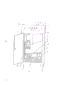
Fig. 2 is the overall structure schematic diagram of self water feeding control device.
As seen from Figure 1, Figure 2, the utility model is when assembling, at first with frequency meter 11, ammeter 12, three switch 13-15 and four indicator lamp 16-19 by fixed-site shown in Figure 2 on the panel on vertical counter 1 top, again with the printed substrate 9,10 that welds, comprise that socket and governor 2, air-break 3, fuse 4, thermal relay 5, inductance coil 6, buzzer 7,8, terminal row are fixed on the liner plate of vertical counter 1 by relative position shown in Figure 2, and with liner plate and vertical counter 1 bolt.Connect up by circuit connecting relation shown in Figure 1 then.Introducing, lead-out wire enter terminal row.
During use, close air-break 3 earlier, close power switch 14,15 again, indicator lamp 16 is bright, relay J behind the time-delay five seconds
1Adhesive, governor 2 power control terminals insert power supply.When the water surface of reservoir surpasses tested liquid level, J
2Adhesive indicator lamp 17 is bright, and two pumps outwards supply water simultaneously to cooperate and realize constant voltage control, also can realize constant voltage control separately.Reservoir is anhydrous, and indicator lamp 19 is bright, and two pumps all stop outside water supply.The constant speed pump generally is lower than the lower limit input as stand by pump at pressure, is higher than higher limit and withdraws from, and fault heating controllable silicon is by the indicator lamp 18 bright warnings simultaneously of cutting off the electricity supply automatically.Buzzer 7 is reported to the police and is stopped to supply water under governor 2 failure conditions, and the constant speed pump drops into when pressure is lower than lower limit automatically, and the elimination of governor 2 faults is restarted will be by reset switch 13, and governor 2 puts into operation automatically.
Claims (5)
1; a kind of self water feeding control device; comprise governor (2); air-break (3); fuse (4); thermal relay (5); inductance coil (6); buzzer (7); (8); frequency meter (11); ammeter (12); switch (13); (14); (15); indicator lamp (16); (17); (18); (19) and voltage-stabilized power supply, it is characterized in that this device is provided with by two bar printing wiring boards (9); (10) and electronic device form stop protection governor (2) wink; the input of governor (2) pressure inverting; the control of constant speed pump pressure; water level is controlled four partial circuits.
2, self water feeding control device according to claim 1 is characterized in that stopping holding circuit governor (2) wink is by resistance (R
1), electric capacity (C
2) get dividing potential drop time-delay input unijunction transistor (T
1), unijunction transistor (T
1) pulse signal of first base stage output is through triode (BG
1) amplification series connection cut-in relay (J
1).
3, self water feeding control device according to claim 1 is characterized in that governor (2) pressure inverting input circuit is with teletransmission pressure meter (W
1) the pressure-dependent voltage signal sent is through resistance (R
6), potentiometer (W
2) enter triode (BG
2) base stage, through triode (BG
2), (BG
3) after two-stage amplifies, again by resistance (R
11) send into the governor signal end.
4, self water feeding control device according to claim 1 is characterized in that constant speed pump pressure control circuit is that pressure controller normally closed contact (YJ) is inserted triode (BG
4) base stage, triode (BG
4) colelctor electrode output through resistance (R
13) signal is imported by unijunction transistor (T
2) and pulse transformer (B
3) the oscillation circuit formed of elementary winding, trigger each phase bidirectional triode thyristor (SCR) by three secondary windings again.
5, self water feeding control device according to claim 1 is characterized in that water-level control circuit is that water level signal is sent into triode (BG
5) amplify the relay (J that control is connected with colelctor electrode
2).
Priority Applications (1)
| Application Number | Priority Date | Filing Date | Title |
|---|---|---|---|
| CN 92245262 CN2148100Y (en) | 1992-12-20 | 1992-12-20 | Automatic water supply controller |
Applications Claiming Priority (1)
| Application Number | Priority Date | Filing Date | Title |
|---|---|---|---|
| CN 92245262 CN2148100Y (en) | 1992-12-20 | 1992-12-20 | Automatic water supply controller |
Publications (1)
| Publication Number | Publication Date |
|---|---|
| CN2148100Y true CN2148100Y (en) | 1993-12-01 |
Family
ID=33784259
Family Applications (1)
| Application Number | Title | Priority Date | Filing Date |
|---|---|---|---|
| CN 92245262 Expired - Fee Related CN2148100Y (en) | 1992-12-20 | 1992-12-20 | Automatic water supply controller |
Country Status (1)
| Country | Link |
|---|---|
| CN (1) | CN2148100Y (en) |
Cited By (1)
| Publication number | Priority date | Publication date | Assignee | Title |
|---|---|---|---|---|
| CN101058015B (en) * | 2006-04-19 | 2010-09-29 | 中芯国际集成电路制造(上海)有限公司 | Fire-fighting constant pressure water supplying system |
-
1992
- 1992-12-20 CN CN 92245262 patent/CN2148100Y/en not_active Expired - Fee Related
Cited By (1)
| Publication number | Priority date | Publication date | Assignee | Title |
|---|---|---|---|---|
| CN101058015B (en) * | 2006-04-19 | 2010-09-29 | 中芯国际集成电路制造(上海)有限公司 | Fire-fighting constant pressure water supplying system |
Similar Documents
| Publication | Publication Date | Title |
|---|---|---|
| CN2148100Y (en) | Automatic water supply controller | |
| CN201574958U (en) | Double-fan control system | |
| CN208908357U (en) | A kind of intelligent electric equipment protecting equipment | |
| CN2109466U (en) | Automatic working device for spare pump | |
| CN205753371U (en) | A kind of breaker control and coil protector | |
| CN212898768U (en) | Diesel engine pump set double-storage-battery switching device matched with direct-current 12V starting motor | |
| CN112431725B (en) | Intelligent wind driven generator | |
| CN201166386Y (en) | Ignition device | |
| US4324542A (en) | Electronic safety device for a fluid, particularly gaseous, fuel burner | |
| CN218760544U (en) | On-line monitoring system for running condition of fan of heavy-current switch equipment | |
| CN205172792U (en) | Safety arrangement of internal -combustion engine | |
| CN216250427U (en) | Low-voltage reactive compensation capacitor device with temperature control detection function | |
| CN210297591U (en) | Safe and energy-saving unattended oil pumping machine control cabinet | |
| CN109459999A (en) | Power station trailer main control module trouble hunting instrument | |
| CN211828400U (en) | Dry-type transformer that radiating effect is good | |
| CN219201756U (en) | Power failure prompting device | |
| CN218004715U (en) | Closing and locking device of circuit breaker | |
| CN217813746U (en) | Braking air brake control system of generator set | |
| CN2527838Y (en) | Gas safety monitor | |
| CN110806765B (en) | Low-temperature starting protection device for control system of wind generating set | |
| CN201835891U (en) | Automatic audible and visual oilless alarm device for engine | |
| CN2171973Y (en) | Electron protecter for transformer of neon lamp | |
| CN2276197Y (en) | Time switch capable of preventing repeated power on | |
| CA1175897A (en) | Pump failure protection for liquid transmission pipelines | |
| KR950001918B1 (en) | Power source remote control device |
Legal Events
| Date | Code | Title | Description |
|---|---|---|---|
| C14 | Grant of patent or utility model | ||
| GR01 | Patent grant | ||
| C19 | Lapse of patent right due to non-payment of the annual fee | ||
| CF01 | Termination of patent right due to non-payment of annual fee |