CN214793118U - Self-hanging type suspension leveling rod - Google Patents
Self-hanging type suspension leveling rod Download PDFInfo
- Publication number
- CN214793118U CN214793118U CN202121120698.2U CN202121120698U CN214793118U CN 214793118 U CN214793118 U CN 214793118U CN 202121120698 U CN202121120698 U CN 202121120698U CN 214793118 U CN214793118 U CN 214793118U
- Authority
- CN
- China
- Prior art keywords
- rod
- leveling rod
- rod body
- leveling
- hanging
- Prior art date
- Legal status (The legal status is an assumption and is not a legal conclusion. Google has not performed a legal analysis and makes no representation as to the accuracy of the status listed.)
- Active
Links
Images


Landscapes
- On-Site Construction Work That Accompanies The Preparation And Application Of Concrete (AREA)
Abstract
The utility model belongs to the technical field of leveling rod, in particular to a self-hanging type hanging leveling rod, which aims at the problems that the leveling rod is difficult to erect in a construction site, the measuring work efficiency is influenced and certain potential safety hazard is caused, and the following proposal is provided, which comprises a leveling rod body, a rod head is arranged at the top end of the leveling rod body, and a hook is arranged at the center of the top of the rod head; the utility model discloses in two fixed steel pipe fixed mounting hang in the building wall, hang the outside of hanging the ring through the couple, make the top of levelling rod body be in the state of hanging, place the bottom of levelling rod body inside spacing through the chi foot again, carry out spacing fixed to the bottom of levelling rod through the gag lever post, the levelling rod is the vertical state under self gravity, thereby accomplish the perpendicular installation of levelling rod body on the building, surveying staff need not be before the building installation during the observation, improve the personal safety of surveying staff when surveing, improve surveying and mapping work efficiency.
Description
Technical Field
The utility model relates to a levelling rod technical field especially relates to a from formula of hanging levelling rod that hangs.
Background
The leveling rod is a rod used for settlement observation, and the leveling rod has an invar rod and a glass fiber reinforced plastic rod according to standard rod types. In the field of settlement observation, the leveling rod is widely applied so far.
Most of leveling rods used at present are straight-plate double-sided or single-sided, general leveling rods need to be placed on settlement observation marks to be measured when settlement observation is carried out, the leveling rods can be divided into positive rod measurement and inverse rod measurement according to field conditions, cross operation conditions often exist on a construction site, and the work efficiency of measurement is influenced while great potential safety hazards are brought to surveying and mapping personnel.
Therefore, a self-hanging suspension leveling rod is needed to solve the problems that the leveling rod is difficult to erect on a construction site, the measuring working efficiency is affected and certain potential safety hazards exist.
SUMMERY OF THE UTILITY MODEL
The utility model provides a from formula of hanging levelling rod that hangs has solved the levelling rod and has erect the difficulty at the job site, influences the problem that measures work efficiency and have certain potential safety hazard.
In order to achieve the above purpose, the utility model adopts the following technical scheme: the utility model provides a from formula of hanging levelling rod that hangs, includes the levelling rod body, the chi head is installed on the top of levelling rod body, the top center department of chi head installs the couple, the top of levelling rod body and below all install with the fixed steel pipe of wall body fixed, two the same equal threaded connection in end of fixed steel pipe has locking bolt, is located the top one side of locking bolt is fixed with and hangs the ring with couple matched with, is located the top the outer surface mounting of fixed steel pipe has with locking bolt matched with lock nut, the chi foot is installed to the bottom of levelling rod body, is located the bottom fixed steel pipe one side is installed and is had the spacing subassembly with chi foot matched with.
Preferably, the limiting assembly comprises a mounting bolt in threaded connection with the fixed steel pipe at the bottom, a mounting nut matched with the mounting bolt is mounted on the outer surface of the fixed steel pipe at the bottom, a limiting frame is fixed at one end of the mounting bolt, the ruler foot is located inside the limiting frame, and a limiting rod is arranged at one end of the limiting frame.
Preferably, the cross-section of the limiting frame is U-shaped, a clamping groove is formed in one end, away from the rotating end of the limiting rod, of the limiting frame, and the other end of the limiting rod extends into the clamping groove.
Preferably, the cross sections of the ruler head and the ruler foot are both U-shaped, and the outer surface of the leveling rod body is respectively contacted with the inner surfaces of the ruler head and the ruler foot.
Preferably, the ruler head and the outer surface of the ruler foot are provided with three through holes distributed in an isosceles triangle shape, a fixing bolt is installed inside the through holes, and a fixing nut is fixed on the outer surface of the fixing bolt.
Preferably, the two fixed steel pipes are distributed in an up-down parallel mode, and the leveling rod body and the fixed steel pipes are vertically distributed.
Compared with the prior art, the beneficial effects of the utility model are that:
1. the utility model discloses in two fixed steel pipe fixed mounting install in the building wall body, install the top and the bottom of levelling rod body with chi head and chi foot respectively through fixing bolt and fixation nut, hang in the outside that hangs the ring through the couple, make the top of levelling rod body be in the suspended state, place the bottom of levelling rod body inside spacing through the chi foot again, carry out spacing fixed through the bottom of gag lever post to the levelling rod, the levelling rod is the vertical state under self gravity, thereby accomplish the perpendicular installation of levelling rod body on the building, surveying staff need not the installation to the levelling rod body before the building during the observation, improve the personal safety of surveying staff when surveing, improve surveying and mapping work efficiency.
2. The utility model discloses the setting of well spacing shape carries out spacing processing to the chi foot of levelling rod body bottom, further improves the stability of levelling rod body when surveing the use, the rotatable mode of gag lever post improves the stability of chi foot installation in spacing, easy to assemble to there is certain clearance simultaneously between spacing subassembly and the chi foot, prevent that the levelling rod body from rocking excessively under effects such as wind-force, can make the levelling rod body stretch out and draw back in the certain limit under the influence of temperature simultaneously.
Drawings
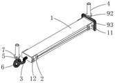
Fig. 1 is a schematic view of the overall structure of a self-hanging type suspension leveling rod of the present invention;
FIG. 2 is a schematic view of the overall structure of FIG. 1 from another perspective;
fig. 3 is a schematic view of a partially enlarged structure at the head of a self-hanging leveling rod according to the present invention;
fig. 4 is a schematic diagram of a local enlarged structure of the position-limiting component of the self-hanging type suspension leveling rod according to the present invention.
In the figure: 1. a leveling rod body; 2. a ruler head; 3. hooking; 4. fixing the steel pipe; 5. locking the bolt; 6. a suspension ring; 7. locking the nut; 8. a ruler foot; 9. a limiting component; 91. installing a bolt; 92. mounting a nut; 93. a limiting frame; 94. a limiting rod; 10. a through hole; 11. fixing the bolt; 12. and (5) fixing the nut.
Detailed Description
The technical solutions in the embodiments of the present invention will be described clearly and completely with reference to the accompanying drawings in the embodiments of the present invention, and it is obvious that the described embodiments are only some embodiments of the present invention, not all embodiments.
Referring to fig. 1-4, a self-hanging type hanging leveling rod comprises a leveling rod body 1, a rod head 2 is installed at the top end of the leveling rod body 1, a hook 3 is installed at the center of the top of the rod head 2, fixing steel pipes 4 fixed to a wall body are installed above and below the leveling rod body 1, locking bolts 5 are connected to the same ends of the two fixing steel pipes 4 through threads, a suspension ring 6 matched with the hook 3 is fixed to one side of the locking bolt 5 at the top, locking nuts 7 matched with the locking bolts 5 are installed on the outer surface of the fixing steel pipe 4 at the top, rod feet 8 are installed at the bottom end of the leveling rod body 1, a limiting component 9 matched with the rod feet 8 is installed on one side of the fixing steel pipe 4 at the bottom, specifically, screw threads are arranged at the fixing steel pipes 4, the locking bolts 5 are used for position adjustment on the fixing steel pipe 4, and the locking bolts 5 are locked through the locking nuts 7, hang on hanging ring 6 through couple 3 this moment, make the top of levelling rod body 1 hang in the wall of building, levelling rod body 1 is the vertical state under self gravity, guarantee the perpendicular installation of levelling rod body 1 and wall, the thickening is carried out to chi foot 8 bottom, further improve the stability of levelling rod body 1 when erectting, spacing subassembly 9's setting, further improve the stability of levelling rod body 1 and the perpendicular installation of fixed steel pipe 4, there is certain clearance simultaneously between spacing subassembly 9 and the chi foot 8, prevent that levelling rod body 1 from excessively rocking under effects such as wind-force, can make levelling rod body 1 stretch out and draw back in the certain limit under the influence of temperature simultaneously.
The cross-section of spacing 93 is the U-shaped, and spacing 93 is kept away from the one end that gag lever post 94 rotated the end and has been seted up the draw-in groove, and inside the other end of gag lever post 94 extended to the draw-in groove, concrete, the setting of spacing 93 shape carried out spacing processing to the chi foot 8 of 1 bottom of levelling rod body, further improved the stability of levelling rod body 1 when surveing the use, and the rotatable mode of gag lever post 94 improves the stability of chi foot 8 installation in spacing 93.
The cross-section of chi head 2 and chi foot 8 all is the U-shaped, and 1 surface of levelling rod body contacts with the internal surface of chi head 2 and chi foot 8 respectively, and is concrete, and chi head 2 presss from both sides tightly the side of levelling rod body 1 with chi foot 8, area of contact when increasing its installation to improve the stability of levelling rod body 1 when perpendicular installation.
Three through-holes 10 that are isosceles triangle and distribute are all seted up with chi head 2 and chi foot 8's surface, and the internally mounted of through-hole 10 has fixing bolt 11, and fixing bolt 11's externally fixed surface has fixation nut 12, and is concrete, fixing bolt 11 and fixation nut 12's setting further improves the stability of levelling rod body 1 and the installation of chi head 2 chi foot 8.
Two fixed steel pipes 4 are parallel distribution from top to bottom, and levelling rod body 1 is perpendicular distribution with fixed steel pipe 4, and is concrete, and parallel distribution from top to bottom guarantees the perpendicular effect of levelling rod body 1 and the perpendicular installation in ground 4.
The working principle is as follows: two fixed steel pipes 4 are fixedly arranged in a building wall, the top end and the bottom end of a leveling rod body 1 are respectively arranged with a rod head 2 and a rod foot 8 through a fixed bolt 11 and a fixed nut 12, at the moment, the positions of the fixed steel pipes 4 are respectively adjusted on the fixed steel pipes 4 through a locking nut 7 and a mounting nut 92 through a locking bolt 5 and a mounting bolt 91, the top end of the leveling rod body 1 is in a hanging state by hanging the hook 3 at the outer side of the hanging ring 6, the bottom end of the leveling rod body 1 is placed in the limiting frame 93 by the rod foot 8, the bottom end of the leveling rod is limited and fixed through the limiting rod 94, thereby completing the vertical installation of the leveling rod body 1 on the building, survey and drawing personnel need not be before the building to the installation of levelling rod body 1 during the observation, improve the personal safety of survey and drawing personnel when surveing, improve survey and drawing work efficiency.
The above, only be the concrete implementation of the preferred embodiment of the present invention, but the protection scope of the present invention is not limited thereto, and any person skilled in the art is in the technical scope of the present invention, according to the technical solution of the present invention and the utility model, the concept of which is equivalent to replace or change, should be covered within the protection scope of the present invention.
Claims (6)
1. A self-hanging type suspension leveling rod comprises a leveling rod body (1) and is characterized in that, the leveling rod comprises a leveling rod body (1), a rod head (2) is installed at the top end of the leveling rod body (1), a hook (3) is installed at the center of the top of the rod head (2), fixed steel pipes (4) fixed with a wall body are installed above and below the leveling rod body (1), locking bolts (5) are connected to the same ends of the two fixed steel pipes (4) in a threaded mode, a hanging ring (6) matched with the hook (3) is fixed to one side of each locking bolt (5) located at the top, locking nuts (7) matched with the locking bolts (5) are installed on the outer surface of each fixed steel pipe (4) located at the top, the leveling rod is characterized in that a rod foot (8) is installed at the bottom end of the leveling rod body (1), and a limiting component (9) matched with the rod foot (8) is installed on one side of the fixed steel pipe (4) located at the bottom.
2. The self-hanging type suspension leveling rod according to claim 1, wherein the limiting assembly (9) comprises a mounting bolt (91) in threaded connection with the bottom fixing steel pipe (4), a mounting nut (92) matched with the mounting bolt (91) is mounted on the outer surface of the bottom fixing steel pipe (4), a limiting frame (93) is fixed to one end of the mounting bolt (91), the rod foot (8) is located inside the limiting frame (93), and a limiting rod (94) is arranged at one end of the limiting frame (93).
3. The self-hanging type hanging leveling rod according to claim 2, wherein the cross section of the limiting frame (93) is U-shaped, a clamping groove is formed in one end, away from the rotating end of the limiting rod (94), of the limiting frame (93), and the other end of the limiting rod (94) extends into the clamping groove.
4. A self-hanging leveling rod according to claim 1, wherein the head (2) and the foot (8) are U-shaped in cross-section, and the outer surface of the leveling rod body (1) is in contact with the inner surfaces of the head (2) and the foot (8), respectively.
5. The self-hanging type hanging leveling rod according to claim 1, wherein three through holes (10) distributed in an isosceles triangle shape are formed in the outer surfaces of the rod head (2) and the rod foot (8), a fixing bolt (11) is installed inside each through hole (10), and a fixing nut (12) is fixed on the outer surface of each fixing bolt (11).
6. The self-hanging type suspension leveling rod according to claim 1, wherein the two fixed steel pipes (4) are arranged in parallel up and down, and the leveling rod body (1) and the fixed steel pipes (4) are arranged vertically.
Priority Applications (1)
| Application Number | Priority Date | Filing Date | Title |
|---|---|---|---|
| CN202121120698.2U CN214793118U (en) | 2021-05-24 | 2021-05-24 | Self-hanging type suspension leveling rod |
Applications Claiming Priority (1)
| Application Number | Priority Date | Filing Date | Title |
|---|---|---|---|
| CN202121120698.2U CN214793118U (en) | 2021-05-24 | 2021-05-24 | Self-hanging type suspension leveling rod |
Publications (1)
| Publication Number | Publication Date |
|---|---|
| CN214793118U true CN214793118U (en) | 2021-11-19 |
Family
ID=78697077
Family Applications (1)
| Application Number | Title | Priority Date | Filing Date |
|---|---|---|---|
| CN202121120698.2U Active CN214793118U (en) | 2021-05-24 | 2021-05-24 | Self-hanging type suspension leveling rod |
Country Status (1)
| Country | Link |
|---|---|
| CN (1) | CN214793118U (en) |
Cited By (1)
| Publication number | Priority date | Publication date | Assignee | Title |
|---|---|---|---|---|
| CN114593717A (en) * | 2022-02-24 | 2022-06-07 | 青建国际集团有限公司 | Wall-attached type building level detection ruler with fixed angle measurement function |
-
2021
- 2021-05-24 CN CN202121120698.2U patent/CN214793118U/en active Active
Cited By (1)
| Publication number | Priority date | Publication date | Assignee | Title |
|---|---|---|---|---|
| CN114593717A (en) * | 2022-02-24 | 2022-06-07 | 青建国际集团有限公司 | Wall-attached type building level detection ruler with fixed angle measurement function |
Similar Documents
| Publication | Publication Date | Title |
|---|---|---|
| CN214793118U (en) | Self-hanging type suspension leveling rod | |
| CN211080987U (en) | High-rise building external scaffolding fixed knot constructs | |
| CN209837698U (en) | Reinforcing apparatus of aluminium alloy template system vertical regulation back of body is stupefied | |
| CN214575849U (en) | Support for installing and positioning steel structural member | |
| CN203230696U (en) | Expansion screw hook for measurement of tunnel peripheral convergence and crown settlement | |
| CN214941085U (en) | Node component of safe steel structure for energy-saving building industry | |
| CN210767831U (en) | Civil engineering construction support | |
| CN210570387U (en) | Retaining wall verticality and flatness detection device | |
| CN217760143U (en) | Novel three-dimensional flexible set rule of curtain | |
| CN217637341U (en) | Anchor bolt support angle measuring device | |
| CN209082995U (en) | A kind of building structure of favorable expandability | |
| CN211716075U (en) | Improve rag bolt of perpendicular installation accuracy | |
| CN218541595U (en) | Suspension type prefabricated shear wall installation straightness inspection device that hangs down | |
| CN217583868U (en) | Mounting bracket of section monitor for building detection | |
| CN217541913U (en) | Template straightness detection device that hangs down | |
| CN213902379U (en) | Novel marker post for architectural survey | |
| CN215055354U (en) | Auxiliary fixing device for reinforcing sinking tank hanging mould | |
| CN221323836U (en) | Non-contact hydrologic monitoring device installing support | |
| CN217076777U (en) | Tower crane attachment system for frame structure | |
| CN216390343U (en) | Floor bridge device | |
| CN211423775U (en) | Ground deformation monitoring connecting device | |
| CN219912312U (en) | Support for building foundation pit monitoring | |
| CN215676776U (en) | Accurate mechanical type climbs a displacement monitoring devices | |
| CN218937376U (en) | Balance bracket for fixing leveling rod | |
| CN210715465U (en) | Screw joint for anti-seismic support and hanger system |
Legal Events
| Date | Code | Title | Description |
|---|---|---|---|
| GR01 | Patent grant | ||
| GR01 | Patent grant |