CN214791854U - Panel assembly of air conditioner and air conditioner with same - Google Patents
Panel assembly of air conditioner and air conditioner with same Download PDFInfo
- Publication number
- CN214791854U CN214791854U CN202121003279.0U CN202121003279U CN214791854U CN 214791854 U CN214791854 U CN 214791854U CN 202121003279 U CN202121003279 U CN 202121003279U CN 214791854 U CN214791854 U CN 214791854U
- Authority
- CN
- China
- Prior art keywords
- microphone
- panel
- assembly
- clamping
- air conditioner
- Prior art date
- Legal status (The legal status is an assumption and is not a legal conclusion. Google has not performed a legal analysis and makes no representation as to the accuracy of the status listed.)
- Active
Links
Images


Abstract
The utility model discloses a panel components of air conditioner and have its air conditioner, according to the utility model discloses a panel components of air conditioner includes: the panel bracket is provided with a clamping installation part and a positioning installation part; the microphone assembly is provided with a clamping protrusion matched with the clamping installation part, and the clamping protrusion abuts against the clamping installation part in a first direction; the positioning installation part protrudes out of the panel support and is suitable for abutting against the outer surface of the microphone assembly so as to limit the displacement of the microphone assembly in a second direction, and the first direction is orthogonal to the second direction. Set up joint installation department and location installation department on the panel support, can fix a position microphone subassembly's a plurality of directions, improved microphone subassembly and panel support's installation reliability. The installation difficulty of the panel component is reduced, and the assembly efficiency of the panel component is improved.
Description
Technical Field
The utility model belongs to the technical field of life electrical apparatus and specifically relates to a panel components and have its air conditioner of air conditioner is related to.
Background
In the correlation technique, the installation of the microphone subassembly of air conditioner is not firm, and the cooperation has the virtual position, rocks easily, assembles the poor scheduling problem of reliability.
SUMMERY OF THE UTILITY MODEL
The utility model discloses aim at solving one of the technical problem that exists among the prior art at least. Therefore, an object of the utility model is to provide a panel component sets up joint installation department and location installation department on panel support of panel component, can fix a position microphone subassembly's a plurality of directions, has improved microphone subassembly and panel support's installation reliability. The installation difficulty of the panel component is reduced, and the assembly efficiency of the panel component is improved.
The utility model discloses still provide an air conditioner with above-mentioned panel components.
According to the utility model discloses a panel components of air conditioner includes: the panel bracket is provided with a clamping installation part and a positioning installation part; the microphone assembly is provided with a clamping protrusion matched with the clamping installation part, and the clamping protrusion abuts against the clamping installation part in a first direction; the positioning installation part protrudes out of the panel support and is suitable for abutting against the outer surface of the microphone assembly so as to limit the displacement of the microphone assembly in a second direction, and the first direction is orthogonal to the second direction.
According to the utility model discloses a panel component through set up joint installation department and location installation department on panel support, has realized having improved the installation reliability of microphone subassembly and panel support to the ascending location of a plurality of directions of microphone subassembly. The installation difficulty of the panel component is reduced, and the assembly efficiency of the panel component is improved.
According to the utility model discloses an embodiment, be formed with in the joint installation department and be suitable for and hold the bellied joint cooperation groove of joint, joint cooperation groove has the just right cooperation groove surface of panel support second direction, the joint protruding with cooperation groove surface ends to.
According to the utility model discloses an embodiment, be formed with microphone subassembly holding tank on the panel support, the location installation department structure is a plurality of and encircles microphone subassembly holding tank sets up. According to an embodiment of the invention, each free end of the positioning and mounting portion is configured as an arc segment bent towards a direction away from the microphone assembly.
According to an embodiment of the present invention, the microphone assembly includes: the outer surface of the microphone box body is provided with the clamping bulge; the microphone box cover is in clamping fit with the microphone box body; the microphone is arranged in the accommodating space defined by the microphone box body and the microphone box cover.
According to the utility model discloses an embodiment, be provided with the microphone mounting hole on the microphone box body, at least part of microphone set up in the microphone mounting hole, be provided with on the panel support with the just right pronunciation hole of microphone.
According to the utility model discloses an embodiment, set up the orientation on the microphone box body the microphone lid is open crosses the line breach.
According to an embodiment of the present invention, the microphone assembly further comprises: a sealing member disposed between the microphone case and the panel bracket.
According to an embodiment of the present invention, the microphone is provided with a microphone cover on the outside.
According to the utility model discloses an embodiment, still set up the fixed part on the panel support, the fixed part is suitable for microphone subassembly with behind the cooperation of joint installation department joint with microphone subassembly is fixed to be linked to each other.
According to the utility model discloses an embodiment, the both sides of microphone box body be provided with fixed part complex journal stirrup, the journal stirrup with the fixed part passes through fastener fixed connection.
An air conditioner according to a second aspect of the present invention is briefly described below.
According to the utility model discloses an air conditioner includes panel support and microphone subassembly, panel subassembly be arbitrary one in the above-mentioned embodiment panel subassembly, because according to the utility model discloses a be provided with the panel subassembly of above-mentioned embodiment on the air conditioner, consequently according to the utility model discloses an installation between panel subassembly and the microphone subassembly is accurate reliable with the location in the air conditioner, and the simple to operate firm in connection of microphone subassembly has improved the quality of air conditioner.
Additional aspects and advantages of the invention will be set forth in part in the description which follows and, in part, will be obvious from the description, or may be learned by practice of the invention.
Drawings
The above and/or additional aspects and advantages of the present invention will become apparent and readily appreciated from the following description of the embodiments, taken in conjunction with the accompanying drawings of which:
fig. 1 is a schematic structural view of an air conditioner according to an embodiment of the present invention;
fig. 2 is an exploded view of an air conditioner according to an embodiment of the present invention;
fig. 3 is a schematic structural view of a panel bracket according to an embodiment of the present invention;
FIG. 4 is an enlarged partial view of circled A in FIG. 3;
FIG. 5 is an enlarged partial view of circle B in FIG. 3;
FIG. 6 is an enlarged partial view of circle C in FIG. 3;
fig. 7 is a schematic structural view of a second face of a panel bracket according to an embodiment of the present invention;
fig. 8 is a schematic view illustrating the second engaging member of the panel bracket and the second engaging portion of the air-out frame according to the embodiment of the present invention;
fig. 9 is a schematic view illustrating the cooperation between the panel bracket and the air outlet frame in the up-down direction;
fig. 10 is a schematic view illustrating the engagement between the panel bracket and the air outlet frame in the front-rear direction according to the embodiment of the present invention;
fig. 11 is an exploded view of a panel assembly according to an embodiment of the present invention;
fig. 12 is a schematic view of the mating of the first face of the panel bracket to the trim panel according to an embodiment of the present invention;
fig. 13 is a structural intention of a decorative panel according to an embodiment of the present invention;
fig. 14 is a structural intent of a panel bracket according to an embodiment of the present invention;
FIG. 15 is an enlarged fragmentary view of circle D in FIG. 14;
FIG. 16 is an enlarged partial view of circled E in FIG. 14;
fig. 17 is a schematic diagram of a microphone assembly and a panel bracket according to an embodiment of the present invention;
fig. 18 is a schematic view of a microphone assembly being snapped to a panel bracket according to an embodiment of the present invention;
FIG. 19 is an enlarged fragmentary view of circle F in FIG. 18;
fig. 20 is an exploded view of a microphone assembly according to an embodiment of the invention;
FIG. 21 is a schematic structural view of an upper portion of an air-out frame according to an embodiment of the present invention;
FIG. 22 is an enlarged partial view of circled G in FIG. 21;
fig. 23 is a partially enlarged view of circle H in fig. 21.
Reference numerals:
the air-conditioner (10) is provided with,
the panel assembly 1 is provided with a panel assembly,
the panel holder 11, the first face 101, the second face 102,
the first fitting part 111 is provided with a first fitting part,
a hook portion 1111, a horizontally extending portion 1111a, a vertically extending portion 1111b, a first surface 111a, a weight-reduction groove 111c,
the support ribs 1112, the second surface 111b,
the second mating member 112, the third surface 112a, the fourth surface 112b,
the adhesive layer 113, the adhesive receiving groove 113a,
a clamping installation part 114, a fixing part 115, an installation boss 116,
a decorative panel 12, a touch screen mounting area 121, an identification line 122, a sound pickup hole 123, a touch screen 124,
the microphone assembly 13 is provided with a microphone assembly,
the air-out frame 2, the first matching part 21 and the second matching part 22.
Detailed Description
Reference will now be made in detail to embodiments of the present invention, examples of which are illustrated in the accompanying drawings, wherein like reference numerals refer to the same or similar elements or elements having the same or similar function throughout. The embodiments described below with reference to the drawings are exemplary only for the purpose of explaining the present invention, and should not be construed as limiting the present invention.
A panel assembly 1 according to an embodiment of the present invention is described below with reference to fig. 1 to 13.
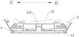
The air conditioner 10 according to the present invention may be an indoor unit of an air conditioner, and may be a cabinet type air conditioner. With reference to fig. 1 and 2, the panel assembly 1 is mounted on the air outlet frame 2 of the air conditioner 10, and the panel assembly 1 can shield the component at the air outlet frame 2, so as to prevent the component from being exposed and improve the aesthetic property of the air conditioner 10.
The display screen is installed to panel assembly 1 in this application, and the user can acquire the operating condition of air conditioner 10 in real time through the display screen, can also adjust the operating condition of air conditioner 10 through the display screen to satisfy user's user demand. The panel assembly 1 serves as a mounting carrier of the display screen, can bear the display screen, and can improve the reliability and the attractiveness of the air conditioner 10.
Wherein the panel assembly 1 comprises a panel bracket 11 and a decorative panel 12, the panel bracket 11 has a first face 101 and a second face 102 facing each other in a first direction, wherein the projections of the first face 101 and the second face 102 in the first direction coincide, the panel bracket 11 may be configured in a plate-like structure, and when the panel bracket 11 is mounted on the air-out frame 2 of the air conditioner 10, the side of the panel bracket 11 facing a user may be the first face 101, and the side facing the air-out frame 2 may be the second face 102.
A decorative panel 12 is disposed on the first side 101, the decorative panel 12 may be used to enhance the aesthetic appearance of the air conditioner 10 on the side facing the user, and the display screen may be a touch screen 124 and mounted on the decorative panel 12.
In some embodiments, the decorative panel 12 may be configured as a glass panel to enhance the tactile feel of the air conditioner 10, to make the user smoother when operating the touch screen 124, and to enhance the user experience.
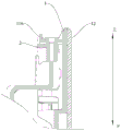
Further, a first fitting member 111 fitted with the air-out frame 2 is provided on the second face 102 of the panel bracket 11, the first fitting member 111 having a first surface 111a and a second surface 111b, the first surface 111a and the second surface 111b being disposed at a distance from each other in the first direction. The first surface 111a and the second surface 111b may define a relative position between the air-out frame 2 and the panel bracket 11 in the first direction.
In the related art, the panel bracket 11 and the air-out frame 2 are mounted by clamping or fastening members, and the conventional connection method can only limit the position between the panel bracket 11 and the air-out frame 2 in one direction, for example, when the panel bracket 11 is mounted on the air-out frame 2, the position between the panel bracket 11 and the air-out frame 2 may have a virtual position, which may shake in the direction perpendicular to the panel bracket 11, thereby affecting the quality of the air conditioner 10.
And according to the utility model discloses a panel component 1, after panel support 11 installs on air-out frame 2, the first cooperation portion 21 that sets up on the air-out frame 2 can be located between first surface 111a and the second surface 111b, and first cooperation portion 21 ends with first surface 111a and second surface 111b respectively to make the position of the restriction of the first cooperation portion 21 of air-out frame 2 between first surface 111a and second surface 111b, restricted panel support 11 and the relative position of air-out frame 2. Make the cooperation between panel support 11 and the air-out frame 2 more firm reliable, avoid appearing virtual position between panel support 11 and the air-out frame 2, make the panel component 1 of this application install to air-out frame 2 after the cooperation on the first direction more reliable and more stable, improved the inseparable degree of installation between panel component 1 and the air-out frame 2, promoted the quality of air conditioner 10.
A second mating member 112 is further disposed on the second side 102 of the panel bracket 11, the second mating member 112 having a third surface 112a and a fourth surface 112b, the third surface 112a and the fourth surface 112b being spaced from each other in the second direction. The third surface 112a and the fourth surface 112b may restrict a relative position between the air-out frame 2 and the panel bracket 11 in the second direction.
Similarly, due to the matching between the panel bracket 11 and the air-out frame 2 in the related art, the panel bracket also needs to be limited in the first direction and the second direction perpendicular to the first direction, and the dimension of the second direction is only matched with one side, so that the panel assembly 1 and the air-out frame 2 are difficult to be kept in stable positions, and the panel assembly 1 and the air-out frame 2 also have the problems of virtual positions and easy shaking in the second direction.
As shown in fig. 8, according to the panel assembly 1 of the present invention, after the panel bracket 11 is mounted on the air-out frame 2, the second mating portion 22 disposed on the air-out frame 2 wraps the second mating member 112, the second mating portion 22 respectively abuts against the third surface 112a and the fourth surface 112b, and the second mating portion 22 respectively abuts against the third surface 112a and the fourth surface 112b, so that the second mating portion 22 of the air-out frame 2 is used for limiting the relative movement between the third surface 112a and the fourth surface 112b on the second mating member 112, and limiting the relative position between the panel bracket 11 and the air-out frame 2. Make the cooperation between panel support 11 and the air-out frame 2 more firm reliable, avoid appearing virtual position between panel support 11 and the air-out frame 2, make the panel component 1 of this application more reliable and more stable in the ascending cooperation of second side after installing to air-out frame 2, improved the inseparable degree of installation between panel component 1 and the air-out frame 2, promoted the quality of air conditioner 10.
Further, the first direction is orthogonal to the second direction, the first direction may be a front-back direction of the air conditioner 10, when the panel assembly 1 is mounted on the air-out frame 2, the first fitting piece 111 of the panel assembly 1 and the first fitting portion 21 of the air-out frame 2 are limited in the front-back direction, so that it is ensured that no virtual position is generated between the panel assembly 1 and the air-out frame 2 in the front-back direction; the second direction can be the left and right directions or the upper and lower direction of air conditioner 10 or the arbitrary direction in the vertical plane, second fitting piece 112 of panel components 1 and the second cooperation portion 22 of air-out frame 2 end up to support in two directions in the vertical plane, thereby restricted panel components 1 and the relative position of air-out frame 2 in the vertical plane, guarantee the relative position between panel components 1 and the air-out frame 2 reliable and stable, the cooperation error between panel components 1 and the air-out frame 2 has been reduced greatly, prevent to take place the dislocation between panel support 11 and the air-out frame 2.
According to the utility model discloses a panel components 1 of air conditioner 10, through set up first fitting piece 111 and second fitting piece 112 on the second face 102 at panel support 11, make panel support 11 and the cooperation of going out between the wind frame 2 more reliable, prescribe a limit to panel support 11 and the relative position of going out between the wind frame 2 from first direction and second direction respectively, improved panel support 11 and the reliability of going out assembly between the wind frame 2.
As shown in fig. 3, 4 and 10, according to an embodiment of the present invention, the first mating member 111 includes a hook portion 1111, a hook notch is provided in the hook portion 1111 to accommodate the first mating portion 21, and a side wall of an inner surface of the hook notch facing the first face 101 is configured as a first surface 111 a.
Wherein, the hook portion 1111 is constructed as a protruding hook disposed on the protruding second surface 102, the first engaging portion 21 can engage with the hook portion 1111, so that the panel assembly 1 is supported on the first engaging portion 21 through the hook portion 1111, and the weight of the panel assembly 1 can be transmitted to the framework structure of the air conditioner 10 through the hook portion 1111 and the first engaging portion 21. And the hook notch 1111 is formed with the couple breach in, the lateral wall that the couple breach faced first surface 111a is first surface 111a, through the surface stop of first surface 111a with first cooperation portion 21, can realize keeping away from the ascending removal in the direction of air-out frame 2 to panel subassembly 1 orientation, restricts the removal of panel subassembly 1 towards the front side promptly.
According to an embodiment of the present invention, the hook portion 1111 includes a horizontal extension portion 1111a and a vertical extension portion 1111b, one end of the horizontal extension portion 1111a is disposed on the second surface 102 and the other end extends toward a direction away from the second surface 102, and the lower surface of the horizontal extension portion 1111a can be supported on the upper surface of the first fitting portion 21, so that the whole weight of the panel assembly 1 is supported on the air-out frame 2 through the hook portion 1111.
The vertical extension 1111b is disposed at the other end of the horizontal extension 1111a and defines a hook gap with the second surface 102, a surface of the vertical extension 1111b facing the second surface 102 is configured as a first surface 111a, and the first surface 111a can limit a relative movement of the hook portion 1111 and the first mating portion 21 in a direction perpendicular to the first direction when being stopped with the first mating portion 21.
As shown in fig. 4, according to an embodiment of the present invention, one side of the vertical extension 1111b departing from the second surface 102 is provided with a plurality of weight reduction grooves 111c, according to the present invention, the hook portion 1111 can be constructed as an integral member with the panel bracket 11, and the hook portion 1111 needs to be used for supporting the panel assembly 1, and the load to be transmitted is large, so the hook portion 1111 needs to have a large volume when designing, but the weight of the whole panel assembly 1 can be increased due to the fact that the volume of the hook portion 1111 is simply increased.
In the present application, by configuring the portion of the vertically extending section 1111b of the hook portion 1111 as a hollow structure to form a plurality of weight-reducing grooves 111c, and forming the support ribs 1112 between two adjacent weight-reducing grooves 111c, the structural strength of the hook portion 1111 is maintained, and the weight of the panel assembly 1 can be reduced by providing the plurality of weight-reducing grooves 111c while maintaining the same load-bearing effect, and the molding cost of the panel assembly 1 can be reduced.
The first surface 111a opposite to the side of the vertically extending section 1111b away from the second surface 102, in which the lightening groove 111c is disposed, may be configured as a flat surface, and the lightening groove 111c does not penetrate through the vertically extending section 1111b, so as to maintain the flatness of the first surface 111a, increase the contact area between the first surface 111a and the first mating portion 21, and improve the reliability of the mating.
As shown in fig. 4, 5, 7 and 10, according to an embodiment of the present invention, the first fitting member 111 further includes a supporting rib 1112, the supporting rib 1112 protrudes from the second surface 102 and protrudes toward the air-out frame 2, and a surface of the supporting rib 1112 facing one side of the air-out frame 2 is configured as a second surface 111 b.
The second surface 111b in the present application is provided on the support rib 1112 instead of taking the entire second face 102 of the panel holder 11 as the second surface 111 b. When the entire second surface 102 of the panel bracket 11 is used as the second surface 111b to mate with the first mating portion 21 of the air-out frame 2, the thickness and weight of the panel assembly 1 are increased, the cost is increased, and the difficulty of assembly is further increased.
This application is through setting up brace 1112, set up brace 1112 on panel support 11's second face 102, and regard brace 1112 as second face 102 towards air-out frame 2 side surface, support out frame 2 with forming solitary structure, under the condition that does not increase panel support 11 thickness, make panel support 11 and air-out frame 2 between realize closely laminating in the first direction, thereby the cost is reduced, second face 102 of panel support 11 and air-out frame 2 are spaced apart simultaneously, the installation clearance has been reserved, it assembles conveniently in the workman, the assembly degree of difficulty between panel support 11 and the air-out frame 2 has been reduced.
Further, as shown in fig. 10, the supporting rib 1112 and the hook portion 1111 may be used in cooperation, the first engaging portion 21 may be configured as a protruding block disposed on the air-out frame 2 and protruding from the surface of the air-out frame 2, a hook engaging groove adapted to receive the vertically extending section 1111b is disposed on the protruding block, and the first surface 111a of the vertically extending section 1111b is abutted against the inner wall of the hook engaging groove to realize the forward direction limitation of the first direction. After the hook portion 1111 is engaged with the hook engaging groove, the surface of the protrusion facing the panel bracket 11 is stopped against the second surface 111b of the support rib 1112, thereby realizing the reverse position limitation in the first direction.
Divide into two kinds of structures of hook portion 1111 and brace rod 1112 with first cooperation portion 21, set up first surface 111a and second surface 111b respectively in two kinds of structural spacing in positive and negative two directions of first direction between panel support 11 and the air-out frame 2, under the condition that does not increase panel support 11 thickness, avoid taking place the phenomenon of virtual position between panel support 11 and the air-out frame 2, improved the cooperation reliability between panel support 11 and the air-out frame 2 subassembly.
According to an embodiment of the present invention, the thickness of the support rib 1112 increases gradually in the direction away from the opening of the hook gap, and it can also be understood that the thickness of the support rib 1112 decreases gradually in the direction of the opening of the hook gap. Wherein the couple breach on pothook portion 1111 can be opened towards the downside, and when installing panel components 1, panel support 11 from top to bottom joint is on air-out frame 2, supports to advance 1112 and is reducing gradually in the thickness in the direction from top to bottom.
In order to ensure that the panel bracket 11 can be assembled smoothly during the assembly process, the contact area and the relative friction between the second surface 111b and the air-out frame 2 need to be reduced.
Therefore, by minimizing the thickness of the lowermost end of the support rib 1112, during the preliminary fitting of the panel holder 11 with the first fitting portion 21, will not bear excessive friction force, ensure the lowest end of the support rib 1112 to contact with the surface of the first matching part 21 of the air-out frame 2 facing the panel bracket 11 first, during further engagement of the hook portion 1111 on the panel bracket 11 with the first engagement portion 21, since the thickness of the support rib 1112 is increased continuously, the contact between the second surface 111b of the support rib 1112 and the first mating portion 21 is also increased, the support rib 1112 supports the first mating portion 21 between the first surface 111a and the second surface 111b, thereby inject the relative movement on the first direction between panel assembly 1 and the air-out frame 2, prevent to take place virtual position between panel assembly 1 and the air-out frame 2, improve the reliability of cooperation between panel assembly 1 and the air-out frame 2.
According to an embodiment of the present invention, the support rib 1112 is disposed adjacent to the hook portion 1111, and the support rib 1112 is disposed adjacent to the hook portion 1111, so that the first surface 111a and the second surface 111b can be closer to each other, when the first engaging portion 21 is limited, the first surface 111a and the second surface 111b are all used to generate positive pressure in the first direction, but the first surface 111a and the second surface 111b can be opposite to each other or not, when the second surface 111b is not opposite to each other, a torque can be generated on the hook portion 1111, and the force applied to the hook portion 1111 is unbalanced. The support rib 1112 is disposed adjacent to the hook portion 1111 to reduce the torque to be applied to the hook portion 1111.
In an embodiment of the present invention, the hook portion 1111 is configured to be a plurality of and arranged at intervals at the periphery of the panel bracket 11, the support ribs 1112 are also configured to be a plurality of in one-to-one correspondence, the extending direction of each support rib 1112 is the same as the extending direction of the vertical extending section 1111b of each hook portion 1111, and each support rib 1112 is disposed adjacent to the hook notch of the hook portion 1111, so that the second surface 111b in the hook notch is closer to the first surface 111a on the support rib 1112.
As shown in fig. 8, according to an embodiment of the present invention, the second fitting member 112 is configured as a limit projection extending away from the second surface 102, and the surfaces of the peripheral walls of the limit projection facing each other in the width direction of the panel holder 11 are configured as a third surface 112a and a fourth surface 112 b. The second matching part 22 disposed on the air-out frame 2 may be provided with a notch structure for accommodating the limiting protrusion, and the inner wall of the notch is provided with an inner wall surface which abuts against the third surface 112a and the fourth surface 112b, so that the movement of the panel bracket 11 on the plane perpendicular to the first direction is limited by the limiting protrusion abutting against the inner wall surface of the notch.
And the plane perpendicular to first direction can be vertical plane, sets up spacing bellied aim at restriction panel support 11 and the relative position between the air-out frame 2, guarantees that panel support 11 can not remove in vertical plane after installing to air-out frame 2, improves the installation accuracy between panel components 1 and the air-out frame 2.
The outer peripheral walls of the limiting protrusions facing each other in width are constructed into a third surface 112a and a fourth surface 112b, the third surface 112a abuts against the inner wall of the gap, and when the fourth surface 112b abuts against the inner wall of the gap, the panel assembly 1 and the air outlet frame 2 are limited in width direction, so that the positions of the panel assembly 1 and the air outlet frame 2 in the left-right direction are kept accurate.
Furthermore, the lower side surface of the peripheral wall of the limiting protrusion can be abutted against the inner wall of the notch, the limiting protrusion can also be used for sharing the weight of the panel assembly 1, and the weight of the panel assembly 1 is transmitted to the air outlet frame 2 through the plurality of hook portions 1111 and the limiting protrusion respectively.
According to the utility model discloses an embodiment, spacing bellied width reduces gradually in the open direction of couple breach, and the couple breach can open towards the downside to install to air-out frame 2 from top to bottom at the in-process of panel components 1 installation, spacing bellied width reduces gradually in the direction from top to bottom. The width of the lower end of the limiting protrusion is small, the lower end of the limiting protrusion can be matched with the notch more easily, coarse positioning between the limiting protrusion and the notch is realized, and the width of the limiting protrusion is gradually increased in the direction from bottom to top, so that the panel assembly 1 is gradually matched with the air outlet frame 2, the distance between the third surface 112a and the fourth surface 112b is gradually increased, the limiting protrusion can be tightly supported in the notch, the third surface 112a and the fourth surface 112b are more tightly contacted with the second matching part 22 in the air outlet frame 2 respectively, and the relative positions of the panel assembly 1 and the air outlet frame 2 in the left-right direction are limited.
The width of the limiting bulge is gradually increased from bottom to top, the assembly difficulty between the panel assembly 1 and the air outlet frame 2 is reduced, the matching precision between the limiting bulge and the second matching part 22 is improved, the position of the panel assembly 1 relative to the air outlet frame 2 in the left-right direction is more accurate, and the panel assembly 1 cannot move relative to the air outlet frame 2 in the left-right direction.
According to the utility model discloses an embodiment, spacing arch sets up in panel support 11 at the ascending center of symmetry of width direction, can guarantee panel support 11's weight balance on the one hand, spacing arch can carry on spacingly at panel support 11's middle part position panel support 11, and pothook portion 1111 sets up the border position at panel support 11, the cooperation structure of two kinds of differences can lead to the assembling process to take place to interfere if setting up too closely, set up spacing arch at the ascending center of symmetry of panel support 11 left and right sides, pothook portion 1111 can be kept away from to messenger spacing arch, cooperation between pothook portion 1111 and the spacing arch does not influence each other.
According to the utility model discloses an embodiment is provided with bonding glue film 113 between decoration panel 12 and the panel support 11, and panel support 11 passes through bonding glue film 113 to be fixed on panel support 11, need not to set up connection structure on decoration panel 12, has reduced the development cost of decoration panel 12, has also simplified the assembly process of panel components 1.
According to the utility model discloses an embodiment is formed with the bonding glue holding tank 113a that is suitable for holding bonding glue layer 113 on the first face 101 of panel support 11, and bonding glue holding tank 113a provides the space for setting up bonding glue layer 113, and bonding glue holding tank 113a can fix a position bonding glue layer 113 simultaneously, ensures that the relative position between bonding glue layer 113 and the panel support 11 is accurate.
In some embodiments, the adhesive receiving groove 113a may be disposed around the periphery of the first face 101, and the decorative panel 12 may couple the periphery of the decorative panel 12 to the panel bracket 11 when secured to the adhesive receiving groove 113. The adhesive receiving groove 113a may include an annular portion surrounding the periphery of the first surface 101, and the annular portion has a first adhesive receiving groove and a second adhesive receiving groove facing each other in the up-down direction, and a third adhesive receiving groove and a fourth adhesive receiving groove facing each other in the width direction, and the first adhesive receiving groove, the third adhesive receiving groove, the second adhesive receiving groove and the fourth adhesive receiving groove are sequentially connected end to form an annular adhesive receiving groove.
The adhesive receiving groove 113a further includes an enhanced adhesive receiving groove disposed between the first adhesive receiving groove and the second adhesive receiving groove or between the third adhesive receiving groove and the fourth adhesive receiving groove, and the enhanced adhesive receiving groove can further bond the center of the decorative panel 12 and the center of the panel, thereby further improving the connection strength between the panel bracket 11 and the decorative panel 12.
According to the utility model discloses an embodiment, bonding glue film 113 can be constructed as the VBH sticky tape, and the bonding strength of VBH sticky tape is high, can ensure the joint strength between decoration panel 12 and the panel.
As shown in fig. 7 and 9, according to an embodiment of the present invention, the upper end of the second face 102 is provided with a mounting boss 116 protruding away from the second face 102, the mounting boss 116 abuts against the air-out frame 2 in the height direction, the mounting boss 116 is fixedly connected to the air-out frame 2, after the panel bracket 11 is fixed to the air-out frame 2, the panel bracket 11 and the air-out frame 2 need to be vertically limited, the mounting boss 116 provided at the upper end of the second face 102 can abut against the surface of the air-out frame 2 in the height direction to limit the displacement of the panel bracket 11 relative to the air-out frame 2 in the height direction, the mounting boss 116 is provided with a plurality of first fastener mounting holes, the first fastener mounting holes can extend in the vertical direction, the air-out frame 2 is provided with second fastener mounting holes corresponding to the first fastener mounting holes, after the mounting boss 116 abuts against the air-out frame 2, the fastener cooperates with first fastener mounting hole and second fastener mounting hole respectively to realize spacing panel support 11 and air-out frame 2 in the upper and lower direction.
According to the utility model discloses a panel component 1, through setting up hook portion 1111 respectively, brace rod 1112, spacing arch and installation base 116, respectively at panel component 1's fore-and-aft direction, about direction and upper and lower direction are injectd panel component 1 and the relative position that goes out between the air-out frame 2, make panel component 1 and the installation between the air-out frame 2 reliable stable, improved panel component 1 and the installation accuracy who goes out between the air-out frame 2, avoid producing the installation virtual position, improved panel component 1's reliability.
As shown in fig. 13, according to an embodiment of the present invention, a touch screen mounting area 121 is disposed on the decoration panel 12, the touch screen mounting area 121 is suitable for mounting a touch screen 124, and an identification line 122 is disposed at an edge of the touch screen mounting area 121. According to the utility model discloses a touch-sensitive screen 124 can be installed in touch-sensitive screen installing zone 121 through the mode of pasting, and for guaranteeing that the installation of touch-sensitive screen 124 is accurate, sets up the installation accuracy of identification line 122 in order to be used for improving touch-sensitive screen 124 through the periphery at touch-sensitive screen installing zone 121, has conveniently optimized assembly process in manual operation or machine identification.
According to the utility model discloses an embodiment, decoration panel 12 can be constructed for glass panels, and identification line 122 can set up on glass panels through the silk screen printing technology.
As shown in fig. 7 and 11, according to an embodiment of the present invention, the panel assembly 1 further includes a microphone assembly 13, the microphone assembly 13 is disposed on the second surface 102, and the microphone assembly 13 can be used to receive the voice sent by the user, so that the air conditioner 10 operates the air conditioner according to the voice command sent by the user, and the functions of the air conditioner 10 are enriched. The glass panel is provided with a sound pickup hole 123 facing the microphone unit 13.
Still be provided with joint installation department 114 on the panel support 11, joint installation department 114 cooperates with microphone subassembly 13 joint, is connected between microphone subassembly 13 and the panel through the mode of joint, can improve assembly efficiency effectively for the production rhythm, the mode through the joint simultaneously need not other spare parts, can reduce the quantity of spare part in the panel subassembly 1.
The snap-fit mounting portion 114 may be configured as a plurality of snaps provided on the panel bracket 11, wherein the second surface 102 protrudes away from the second surface 102, and the microphone assembly 13 is provided with a plurality of latches corresponding to the snaps, wherein the latches and the snaps cooperate to stop in the first direction to limit the movement of the microphone assembly 13 in the first direction.
Simultaneously, a plurality of buckles can also be used for supporting microphone subassembly 13 in the upper and lower direction, can also carry out spacingly to microphone subassembly 13's position in the left and right sides direction, improves microphone subassembly 13's installation accuracy.
The panel bracket 11 is further provided with a fixing portion 15, and the fixing portion 15 is suitable for being fixedly connected with the microphone assembly 13 after the microphone assembly 13 is clamped and matched with the clamping installation portion 114. The fixing portion 15 may be configured as a boss structure formed on the second surface 102, a lug opposite to the boss structure in the first direction is provided in the microphone assembly 13, a fastener through hole is provided on the lug, and a third fastener mounting hole may be provided on the boss structure, and the fastener through hole is matched with the third fastener mounting hole to press the microphone assembly 13 on the fixing portion 15.
In the above description of the present invention, the first direction may be a front-rear direction perpendicular to the decorative panel 12, the panel bracket 11, and the air-out frame 2; the second direction may be a width direction of the decorative panel 12, the panel bracket 11, and the air-out frame 2.
An air conditioner 10 according to a second aspect of the present invention is briefly described below.
According to the utility model discloses an air conditioner 10 is including going out fan frame 2 and panel components 1, and panel components 1 sets up on going out fan frame 2, panel components 1 be arbitrary one in the above-mentioned embodiment panel components 1, because according to the utility model discloses an air conditioner 10 is last to be provided with the panel components 1 of the above-mentioned embodiment, consequently according to the utility model discloses an installation and the location of panel components 1 are accurate reliable in air conditioner 10, and panel components 1 and the play connection between the fan frame 2 are difficult to take place to rock, have improved air conditioner 10's quality.
A panel assembly 1 according to an embodiment of the present invention is described below with reference to fig. 14 to 20.
According to the utility model discloses a panel assembly 1 includes panel support 11 and microphone subassembly 13, and panel assembly 1 can be installed on air conditioner 10 indoor set, and air conditioner 10 indoor set can be for the cabinet-type air conditioner, can further enrich the function of air conditioner 10 through setting up microphone subassembly 13, and can improve microphone subassembly 13's integrated level with microphone subassembly 13 setting on panel support 11 of panel assembly.
The panel bracket 11 is provided with a snap-fit mounting portion 114, and a snap-fit protrusion 1312 is provided on an outer surface of the microphone assembly 13, wherein the snap-fit protrusion 1312 can abut against the snap-fit mounting portion 114 in the first direction to limit the movement of the microphone assembly 13 relative to the panel bracket 11 in the first direction. It should be noted that the first direction may be an assembling direction of the microphone assembly 13, for example, the first direction may be a front-back direction of the air conditioner 10, the snap-fit mounting portion 114 may be disposed on the second surface 102 of the panel bracket 11, and during the mounting process, the microphone assembly 13 may be mounted on the panel bracket 11 from a back to a front on a back side of the panel bracket 11.
The one-directional position of the microphone assembly 13 is achieved by the click projection 1312 abutting the click mounting portion 114 in the first direction.
A positioning mounting portion 117 is further provided on the panel bracket 11, and the positioning mounting portion 117 is configured to abut against an outer surface of the microphone assembly 13 in the second direction, thereby limiting displacement of the microphone assembly 13 in the second direction. The second direction may be any direction in a plane perpendicular to the first direction.
For example, the second direction may be an up-down direction, and the microphone assembly 13 is further limited in the up-down direction by the positioning and mounting portion 117, so as to further improve the accuracy of the position of the microphone assembly 13, and improve the reliability of the fitting of the microphone assembly 13 with the panel bracket 11.
In other embodiments, the second direction may also be a left-right direction.
Furthermore, the positioning and mounting portion 117 can limit the position of the microphone assembly 13 in the up-down and left-right directions, so as to ensure that the microphone assembly 13 maintains the relative position with the panel bracket 11 after being clamped and fixed to the panel bracket 11.
According to the utility model discloses a panel component 1 through set up joint installation department 114 and location installation department 117 on panel support 11, has realized the location to microphone subassembly 13a plurality of ascending directions, has improved the installation reliability of microphone subassembly 13 with panel support 11. The installation difficulty of the panel component 1 is reduced, and the assembly efficiency of the panel component 1 is improved.
According to an embodiment of the present invention, a card fitting groove 114a adapted to receive the card protrusion 1312 is formed in the card mounting portion 114, the surface of the card fitting groove 114a facing the second surface 102 and the card protrusion 1312 limit the microphone assembly 13 in the front-rear direction of the panel bracket 11, and a card fitting groove surface facing right in the second direction is further formed in the card fitting groove 114a, and the card protrusion 1312 and the card fitting groove 114a are surface-stopped.
As shown in fig. 15, the snap-fit groove 114a may be configured as a rectangular groove, and a rear side surface of the rectangular groove abuts against the snap projection 1312 in the first direction, that is, in the front-rear direction, two surfaces facing each other in the rectangular groove may face each other in the up-down direction or the left-right direction, and after the snap projection 1312 is received in the snap-fit groove 114a, an end surface of the snap projection 1312 in the up-down direction or the left-right direction abuts against an inner surface of the rectangular groove, so that the snap-fit mounting portion 114 and the snap projection 1312 are further restrained in the second direction, and the fitting reliability between the microphone assembly 13 and the panel holder 11 is further improved.
Furthermore, the clamping protrusion 1312 is arranged on the microphone assembly 13, the deformation amount of the clamping protrusion 1312 is small, the deflection change of the free end of the clamping installation part 114 is small, the plastic deformation is not easy to occur, and the possibility of failure of the clamping installation part 114 is reduced.
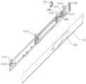
As shown in fig. 14, according to an embodiment of the present invention, a microphone assembly receiving groove 104 is formed on the panel bracket 11, the positioning installation portion 117 is configured in a plurality and is disposed around the microphone assembly receiving groove 104, so that the positioning installation portion 117 can surround the outer periphery of the microphone assembly 13, and the positioning installation portion 117 can surround the microphone 133 in a vertical plane perpendicular to the first direction to restrict the microphone assembly 13 from moving in a plane perpendicular to the first direction. On the one hand, the positioning accuracy of the microphone assembly 13 can be improved, and on the other hand, the positioning mount 117 can carry the weight of the microphone assembly 13 in the vertical plane.
As shown in fig. 14 and 17, according to an embodiment of the present invention, the free end of each positioning and mounting portion 117 is bent, and the free end of each positioning and mounting portion 117 is configured as an arc-shaped segment bent toward a direction away from the microphone assembly 13. The plurality of positioning installation parts 117 are distributed in a vertical plane, the microphone assembly 13 is positioned in the vertical plane after the microphone assembly 13 is installed on the panel bracket 11 in the front and back direction, during the installation process, the free end of the positioning installation part 117 may interfere with the peripheral wall of the microphone assembly 13, and the microphone assembly 13 is prevented from being assembled, and the free end of each positioning installation part 117 is configured into an arc-shaped section bending towards the direction far away from the microphone assembly 13, so that during the assembly process, the microphone assembly 13 is firstly contacted with the arc-shaped section and is gradually positioned to the correct position under the guidance of the arc-shaped section, and the installation difficulty of the microphone assembly 13 is reduced.
As shown in fig. 20, according to an embodiment of the present invention, the microphone assembly 13 includes a microphone case 131, a microphone case cover 132 and a microphone 133, the microphone case 131 may be configured as a cube, and a plurality of clamping protrusions 1312 are provided on an outer circumferential surface of the microphone case 131 for being matched with the clamping installation portion 114, the clamping protrusions 1312 and the clamping installation portion 114 are configured as a plurality in a one-to-one correspondence, and a clamping matching groove 114a is formed in at least one of the clamping installation portions 114 for limiting movement of the clamping protrusions 1312 in the second direction.
Also fixed through the joint cooperation between microphone box body 131 and the microphone lid 132, be provided with accommodation space in the microphone box body 131, microphone lid 132 can cover and establish the open mouthful department of accommodation space at microphone lid 132 to seal microphone lid 132. A plurality of snap rings 1321 are provided on the outer circumference of the microphone case cover 132, and a plurality of protrusions engaged with the snap rings 1321 are provided on the outer circumference of the microphone case body 131, and the protrusions are abutted against the inner surface of the snap rings 1321, so that the microphone case cover 132 is engaged with and fixed to the microphone case body 131.
A microphone 133 is also disposed in the microphone assembly 13, and the microphone 133 can be disposed in the accommodating space for receiving voice commands issued by the user.
According to the utility model discloses an embodiment is provided with microphone mounting hole 1311 on the microphone box body 131, and microphone 133 at least part sets up in microphone mounting hole 1311, is provided with the pronunciation hole 103 just right with microphone mounting hole 1311 on the panel support 11, and the pronunciation that the user sent can pass through pronunciation hole 103 and transmit to microphone 133 to make microphone subassembly 13 receive the pronunciation that the user sent.
The decoration panel 12 is arranged on the panel bracket 11, the sound pickup holes 123 right opposite to the microphones 133 are arranged on the decoration panel 12, the number of the microphones 133 can be multiple, the sound pickup holes 123 and the microphones 133 are arranged in a one-to-one correspondence manner, and the sound pickup holes 123 are arranged to reduce the separation of the decoration panel 12 on sound, so that the accuracy of the voice recognition of the microphone assembly 13 is improved.
According to the utility model discloses an embodiment is provided with on the microphone 133 casing towards the microphone lid 132 open cross line breach 1313, crosses opening of line breach 1313 end and microphone lid 132 and ends to seal the breach in the open direction of crossing line breach 1313, and the pencil can enter into to the internal portion of microphone 133 through crossing line breach 1313, in order to realize the connection of the inside components and parts of microphone subassembly 13.
According to an embodiment of the present invention, the microphone assembly 13 further includes a sealing member 134, the sealing member 134 is disposed between the microphone case 131 and the panel bracket 11, and the sealing member 134 can be configured as a sealing sponge for improving the air tightness between the microphone assembly 13 and the panel bracket 11, so as to make the elements inside the microphone assembly 13 more stable and reliable.
According to the utility model discloses an embodiment, microphone 133's the outside is provided with miaow cover 135, and miaow cover 135 can overlap and establish in microphone 133's periphery in order to be used for noise absorption, reduces the noise that microphone 133 received to further improve microphone subassembly 13's speech recognition rate of accuracy.
According to an embodiment of the present invention, the two sides of the microphone case 131 are provided with the support lugs 1314 matched with the fixing portion 115, the fixing portion 115 can be configured to form a boss structure on the second surface 102, the support lugs 1314 are provided with the fastener through holes, and the boss structure can be provided with the third fastening installation holes, and the fastener through holes are matched with the third fastening installation holes to compress the microphone assembly 13 on the fixing portion 115.
A connecting rib is arranged between the support lug 1314 and the microphone case body 131 to improve the connection strength between the support lug 1314 and the outer peripheral wall of the microphone case body 131.
The panel holder 11 is formed with a microphone assembly receiving groove 104, and the microphone assembly 13 is stopped by the side walls of the receiving groove facing each other in the width direction. An installation position for installing the microphone assembly 13 is provided on the panel bracket 11, the installation position may be configured as a microphone assembly receiving groove 104, the clamping installation part 114 and the positioning installation part 117 may be both provided at the periphery of the bottom wall of the microphone assembly receiving groove 104, and a voice hole 103 is further provided on the bottom wall of the microphone assembly receiving groove 104, so that the microphone 133 picks up sound through the voice hole 103 after the microphone assembly 13 is installed. The side walls facing each other in the width direction of the microphone set accommodating groove 104 may abut against the side walls of the microphone case 131 in the width direction to restrict the movement of the microphone set 13.
An air conditioner 10 according to a second aspect of the present invention is briefly described below.
According to the utility model discloses an air conditioner 10 includes panel support 11 and microphone subassembly 13, panel subassembly 1 is arbitrary one in the above-mentioned embodiment panel subassembly 1, because according to the utility model discloses an air conditioner 10 is last to be provided with the panel subassembly 1 of above-mentioned embodiment, consequently according to the utility model discloses an installation between panel subassembly 1 and the microphone subassembly 13 is accurate reliable with the location in air conditioner 10, and microphone subassembly 13's simple to operate firm in connection has improved air conditioner 10's quality.
In the description of the present invention, it is to be understood that the terms "center", "longitudinal", "lateral", "length", "width", "thickness", "upper", "lower", "front", "rear", "left", "right", "vertical", "horizontal", "top", "bottom", "inner", "outer", "clockwise", "counterclockwise", "axial", "radial", "circumferential", and the like, indicate the orientation or positional relationship based on the orientation or positional relationship shown in the drawings, and are only for convenience of description and simplicity of description, and do not indicate or imply that the device or element referred to must have a particular orientation, be constructed and operated in a particular orientation, and therefore, should not be construed as limiting the present invention.
In the description of the present invention, "the first feature" and "the second feature" may include one or more of the features.
In the description of the present invention, "a plurality" means two or more.
In the description of the present invention, the first feature "on" or "under" the second feature may include the first and second features being in direct contact, and may also include the first and second features being in contact with each other not directly but through another feature therebetween.
In the description of the invention, the first feature being "on", "above" and "above" the second feature includes the first feature being directly above and obliquely above the second feature, or merely indicating that the first feature is at a higher level than the second feature.
In the description herein, references to the description of the term "one embodiment," "some embodiments," "an illustrative embodiment," "an example," "a specific example," or "some examples" or the like mean that a particular feature, structure, material, or characteristic described in connection with the embodiment or example is included in at least one embodiment or example of the present invention. In this specification, the schematic representations of the terms used above do not necessarily refer to the same embodiment or example. Furthermore, the particular features, structures, materials, or characteristics described may be combined in any suitable manner in any one or more embodiments or examples.
While embodiments of the present invention have been shown and described, it will be understood by those of ordinary skill in the art that: various changes, modifications, substitutions and alterations can be made to the embodiments without departing from the principles and spirit of the invention, the scope of which is defined by the claims and their equivalents.
Claims (12)
1. A panel assembly of an air conditioner, comprising:
the panel bracket is provided with a clamping installation part and a positioning installation part;
the microphone assembly is provided with a clamping protrusion matched with the clamping installation part, and the clamping protrusion abuts against the clamping installation part in a first direction;
the positioning installation part protrudes out of the panel support and is suitable for abutting against the outer surface of the microphone assembly so as to limit the displacement of the microphone assembly in a second direction, and the first direction is orthogonal to the second direction.
2. The panel assembly of the air conditioner as claimed in claim 1, wherein a clamping fitting groove adapted to receive the clamping protrusion is formed in the clamping mounting portion, the clamping fitting groove has a fitting groove surface right facing to the second direction of the panel bracket, and the clamping protrusion abuts against the fitting groove surface.
3. The panel assembly of claim 2, wherein a microphone assembly receiving groove is formed on the panel bracket, and the positioning and mounting part is constructed in a plurality and arranged around the microphone assembly receiving groove.
4. The air conditioner panel assembly as claimed in claim 3, wherein the free end of each of said positioning and mounting portions is configured as an arc-shaped segment bent toward a direction away from the microphone assembly.
5. The panel assembly of claim 1, wherein the microphone assembly comprises:
the outer surface of the microphone box body is provided with the clamping bulge;
the microphone box cover is in clamping fit with the microphone box body;
the microphone is arranged in the accommodating space defined by the microphone box body and the microphone box cover.
6. The panel unit of claim 5, wherein the microphone case has a microphone mounting hole, at least a portion of the microphone is disposed in the microphone mounting hole, and the panel bracket has a voice hole opposite to the microphone.
7. The panel assembly of claim 6, wherein the microphone case body is provided with a wire passing notch opened toward the microphone case cover.
8. The panel assembly of claim 6, wherein the microphone assembly further comprises: a sealing member disposed between the microphone case and the panel bracket.
9. The panel assembly of claim 8, wherein a microphone sleeve is provided on an outer side of the microphone.
10. The panel assembly of claim 5, wherein the panel bracket is further provided with a fixing portion, and the fixing portion is adapted to be fixedly connected with the microphone assembly after the microphone assembly is clamped and matched with the clamping mounting portion.
11. The panel assembly of claim 10, wherein the microphone case is provided at both sides thereof with support lugs engaged with the fixing portions, and the support lugs are fixedly connected with the fixing portions by fasteners.
12. An air conditioner characterized by comprising the panel assembly as recited in any one of claims 1 to 11.
Priority Applications (1)
| Application Number | Priority Date | Filing Date | Title |
|---|---|---|---|
| CN202121003279.0U CN214791854U (en) | 2021-05-11 | 2021-05-11 | Panel assembly of air conditioner and air conditioner with same |
Applications Claiming Priority (1)
| Application Number | Priority Date | Filing Date | Title |
|---|---|---|---|
| CN202121003279.0U CN214791854U (en) | 2021-05-11 | 2021-05-11 | Panel assembly of air conditioner and air conditioner with same |
Publications (1)
| Publication Number | Publication Date |
|---|---|
| CN214791854U true CN214791854U (en) | 2021-11-19 |
Family
ID=78693349
Family Applications (1)
| Application Number | Title | Priority Date | Filing Date |
|---|---|---|---|
| CN202121003279.0U Active CN214791854U (en) | 2021-05-11 | 2021-05-11 | Panel assembly of air conditioner and air conditioner with same |
Country Status (1)
| Country | Link |
|---|---|
| CN (1) | CN214791854U (en) |
-
2021
- 2021-05-11 CN CN202121003279.0U patent/CN214791854U/en active Active
Similar Documents
| Publication | Publication Date | Title |
|---|---|---|
| US11930291B2 (en) | Display module and television | |
| US6536855B2 (en) | Front cabinet and television set | |
| GB2381064A (en) | Roof lamp fixing structure | |
| US11800052B2 (en) | Display module and television | |
| CN105355143B (en) | A kind of display product frame and its production technology | |
| CN214791854U (en) | Panel assembly of air conditioner and air conditioner with same | |
| JP5113345B2 (en) | Liquid crystal display | |
| CN215909386U (en) | Air conditioner | |
| JP2005180793A (en) | Air conditioner | |
| CN211823452U (en) | Household electrical appliances display screen mounting structure, refrigerator display screen door body, refrigerator | |
| WO2006090543A1 (en) | Panel attaching bracket and display device | |
| CN115325687A (en) | Air conditioner | |
| CN110595068A (en) | Gas heater face lid subassembly and gas heater | |
| CN106820808B (en) | A kind of screen corner component and the screen using it | |
| CN211823454U (en) | Household appliance display screen mounting structure with horn, refrigerator display screen door body and refrigerator | |
| CN209068718U (en) | A kind of decorative strip of air conditioner assembling structure and air conditioner | |
| CN217835535U (en) | Side wall window assembly and vehicle | |
| CN219164728U (en) | Horn net installation component and playback equipment | |
| CN217948552U (en) | Door seal structure and clothes dryer | |
| CN212064202U (en) | Ornamental strip and TV set of TV set front cover | |
| CN218333113U (en) | Voice module and robot | |
| CN210638303U (en) | Gas heater face lid subassembly and gas heater | |
| CN210864351U (en) | Formula hanging control panel is inhaled to magnetism | |
| CN215499568U (en) | Vehicle microphone | |
| CN217482979U (en) | Air conditioner panel decoration strip, air conditioner shell assembly and air conditioner |
Legal Events
| Date | Code | Title | Description |
|---|---|---|---|
| GR01 | Patent grant | ||
| GR01 | Patent grant |