CN214778132U - Full-closed receiving and storing storage bin - Google Patents
Full-closed receiving and storing storage bin Download PDFInfo
- Publication number
- CN214778132U CN214778132U CN202121006451.8U CN202121006451U CN214778132U CN 214778132 U CN214778132 U CN 214778132U CN 202121006451 U CN202121006451 U CN 202121006451U CN 214778132 U CN214778132 U CN 214778132U
- Authority
- CN
- China
- Prior art keywords
- bearing plate
- bin
- totally enclosed
- bearing
- machine body
- Prior art date
- Legal status (The legal status is an assumption and is not a legal conclusion. Google has not performed a legal analysis and makes no representation as to the accuracy of the status listed.)
- Active
Links
Images


Abstract
The utility model discloses a totally enclosed receiving and storing stock bin body, which is horizontally and stably placed in a factory building, a servo motor is fixed on the outer bolt on the left side of the body, a bearing plate is fixed in the body by welding, and a spiral flood dragon is installed on the inner bearing of the lower end of the body; the bin body is movably arranged inside the upper end of the machine body and is placed above the bearing plate, and a connecting hose is connected between the bin body and the bearing plate in a hot melting mode; the method comprises the following steps: the bearing of the conical tooth disc is mounted in the middle of the lower end of the bearing plate, a hemispherical sieve drum is welded at the lower end of the conical tooth disc, and the sieve drum is positioned above one end of the spiral flood dragon; and a guide groove which penetrates through the inside of the receiving plate. This feed bin organism is stored in totally enclosed receipt avoids the material when the ejection of compact, takes place to pile up in the internal portion in storehouse, can realize the ration unloading to the material simultaneously, improves whole practicality.
Description
Technical Field
The utility model relates to a store feed bin technical field, specifically be totally enclosed and receive and store feed bin.
Background
Store the feed bin and provide the place of storing for the material that uses in the production and processing process, the feed bin is totally enclosed for most storage, has guaranteed that the material does not receive external impurity's influence, nevertheless current storage feed bin still has following problem:
the storage bin with the auxiliary discharging function disclosed in the publication No. CN211769053U solves the technical problems that in the storage process of the existing storage bin, a bin gate for directly discharging is generally adopted to lead out the powder in the storage bin, but because the powder in the storage bin is accumulated for a long time, the caking phenomenon easily occurs, the powder is further led out from the discharge bin, the blockage phenomenon of a bin outlet door caused by the powder is easily caused, and the discharging work efficiency of the storage bin is further reduced, a controller controls a closing device to open and close, so that the powder in the storage bin is freely discharged, the powder is ground through a discharging structure, the caked powder is scattered and converted into fine powder, the discharging port is prevented from being blocked by the caked powder, the discharging work efficiency of the storage bin is improved, when the storage bin discharges the material through opening a baffle, the material is very easy to accumulate on one side of the inner part of the storage bin body, meanwhile, the quantitative discharging of the materials is inconvenient to realize, and the practicability is low.
We propose a totally enclosed receiving and storing silo in order to solve the problems set out above.
SUMMERY OF THE UTILITY MODEL
An object of the utility model is to provide a totally enclosed receives stores feed bin to when solving the current storage feed bin of on the existing market that above-mentioned background art provided and carrying out the ejection of compact to the material through opening the baffle, the material very easily piles up in inside one side of storing the feed bin body, inconvenient realization is to the quantitative ejection of compact of material, the lower problem of practicality simultaneously.
In order to achieve the above object, the utility model provides a following technical scheme: the totally enclosed type receives and stores the feed bin:
the machine body is horizontally and stably placed in a factory building, a servo motor is fixed on the outer portion of the left side of the machine body through a bolt, a bearing plate is fixed inside the machine body in a welded mode, and a spiral flood dragon is installed on a bearing inside the lower end of the machine body;
the bin body is movably arranged inside the upper end of the machine body and is placed above the bearing plate, and a connecting hose is connected between the bin body and the bearing plate in a hot melting mode;
the method comprises the following steps:
the bearing of the conical tooth disc is mounted in the middle of the lower end of the bearing plate, a hemispherical sieve drum is welded at the lower end of the conical tooth disc, and the sieve drum is positioned above one end of the spiral flood dragon;
and a guide groove which penetrates through the inside of the receiving plate.
Preferably, the inside of organism has 4 groups of awl fluted roller such as angularly distributed, just the awl fluted roller with be connected for the bearing between the organism, and one of them the awl fluted roller with servo motor's output interconnect, 4 moreover the awl fluted roller all constitutes the meshing structure with the awl fluted disc, simultaneously wherein 1 be connected with the drive belt between awl fluted roller and the spiral flood dragon for after servo motor starts, can realize holistic stability operation through the engaging action between awl fluted roller and the awl fluted disc.
Preferably, the through-holes have evenly been seted up respectively in the middle part of awl fluted disc and accepting the board, just the through-holes on awl fluted disc and the accepting board correspond the distribution each other for the awl fluted disc rotates the back, accepts the through-hole that corresponds each other and set up between board and the awl fluted disc, can realize quantitative unloading to the material.
Preferably, the inside laminating of guide way is provided with the regulation pole, just the central axis of guide way is parallel to each other with the central axis of organism for adjust the pole and can restrict the direction of reciprocating under the effect of guide way.
Preferably, the lower end of the adjusting rod is attached with a cam, the cam is fixedly installed in the middle of the conical tooth roller, and a pressure spring is welded between the adjusting rod and the bearing plate, so that the adjusting rod can move up and down under the action of the cam and the pressure spring.
Preferably, the upper end welded fastening of adjusting the pole has the control panel, just the control panel is the slope form setting, and the up end of control panel with the lower terminal surface of the storehouse body is laminated each other for the storehouse body can be under the effect of control panel, and the shake about realizing, and then can avoid the material to take place to pile up in storehouse internal portion.
Compared with the prior art, the beneficial effects of the utility model are that: the totally enclosed receiving and storing bin;
1. the automatic discharging device is provided with the control panel and the adjusting rod, so that after one of the bevel gear rollers is driven by the servo motor to rotate, 4 bevel gear rollers synchronously rotate through the meshing action between the bevel gear rollers and the bevel gear disc, and further can drive the cam to continuously extrude the adjusting rod, so that the bin body can shake up and down under the assistance of the control panel, materials in the bin body can be vibrated by external force to fall off, and the situation that the materials are accumulated in the bin body to influence the discharging condition is avoided;
2. be provided with the awl fluted disc and accept the board for after the awl fluted disc took place to rotate under the meshing between with the awl fluted roller, the material can fall from the through-hole of accepting board and awl fluted disc middle part to the realization is to the ration blanking of material in proper order, and the material will be under the effect of continuous pivoted sieve section of thick bamboo, can avoid taking place the caking, improves the result of use of follow-up material, and then can discharge outside the organism through spiral flood dragon, improves the practicality.
Drawings
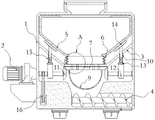
FIG. 1 is a schematic view of a front cross-sectional structure of the present invention;
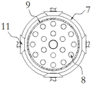
FIG. 2 is a schematic view of a dive structure of a bevel gear disc of the present invention;
FIG. 3 is a schematic view of a cam profile structure of the present invention;
FIG. 4 is a schematic view of a front cross-section structure of the adjusting rod of the present invention;
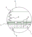
fig. 5 is an enlarged schematic view of a portion a in fig. 1 according to the present invention.
In the figure: 1. a body; 2. a servo motor; 3. a bearing plate; 4. a spiral flood dragon; 5. a bin body; 6. a connecting hose; 7. a conical fluted disc; 8. a through hole; 9. a screen cylinder; 10. a guide groove; 11. a tapered tooth roller; 12. a cam; 13. adjusting a rod; 14. a control panel; 15. a pressure spring; 16. a transmission belt.
Detailed Description
The technical solutions in the embodiments of the present invention will be described clearly and completely with reference to the accompanying drawings in the embodiments of the present invention, and it is obvious that the described embodiments are only some embodiments of the present invention, not all embodiments. Based on the embodiments in the present invention, all other embodiments obtained by a person skilled in the art without creative work belong to the protection scope of the present invention.
Referring to fig. 1-5, the present invention provides a technical solution: totally enclosed receives stores feed bin, including organism 1, servo motor 2, accept board 3, spiral flood dragon 4, the storehouse body 5, coupling hose 6, awl fluted disc 7, through-hole 8, a sieve section of thick bamboo 9, guide way 10, awl fluted roller 11, cam 12, regulation pole 13, control panel 14, pressure spring 15 and drive belt 16:
the machine body 1 is horizontally and stably placed in a factory building, a servo motor 2 is fixed on the outer portion of the left side of the machine body 1 through a bolt, a bearing plate 3 is fixed inside the machine body 1 in a welded mode, and a spiral flood dragon 4 is installed on a bearing inside the lower end of the machine body 1;
the bin body 5 is movably arranged inside the upper end of the machine body 1, the bin body 5 is placed above the bearing plate 3, and a connecting hose 6 is connected between the bin body 5 and the bearing plate 3 in a hot melting mode;
the method comprises the following steps:
the bearing of the conical fluted disc 7 is arranged in the middle of the lower end of the bearing plate 3, the lower end of the conical fluted disc 7 is welded with a hemispherical sieve drum 9, and the sieve drum 9 is positioned above one end of the spiral flood dragon 4;
a guide groove 10 that is provided in the receiving plate 3 in a penetrating manner;
4 groups of bevel rollers 11 are distributed in the machine body 1 at equal angles, the bevel rollers 11 are connected with the machine body 1 through bearings, one of the bevel rollers 11 is connected with the output end of the servo motor 2, the 4 bevel rollers 11 and the bevel gear disc 7 form a meshing structure, meanwhile, a transmission belt 16 is connected between the 1 bevel roller 11 and the spiral auger 4, through holes 8 are respectively and uniformly formed in the middle parts of the bevel gear disc 7 and the bearing plate 3, the bevel gear disc 7 and the through holes 8 on the bearing plate 3 are correspondingly distributed, as shown in figures 1-2 and 5, after the servo motor 2 is started, the servo motor 2 drives one of the bevel rollers 11 to rotate, as the 4 bevel rollers 11 are respectively meshed with the bevel gear disc 7, the transmission belt 16 is sleeved between the spiral auger 4 and the bevel rollers 11, and further the 4 bevel rollers 11, the bevel gear disc 7 and the spiral auger 4 can realize synchronous rotation, due to the fact that the through holes 8 are correspondingly formed between the bearing plate 3 and the bevel gear disc 7 up and down, materials can intermittently fall from the through holes 8 in the rotating process of the bevel gear disc 7, and quantitative blanking of the materials is achieved;
an adjusting rod 13 is attached inside the guide groove 10, the central axis of the guide groove 10 is parallel to the central axis of the machine body 1, a cam 12 is attached to the lower end of the adjusting rod 13, the cam 12 is fixedly installed in the middle of the conical tooth roller 11, a pressure spring 15 is welded between the adjusting rod 13 and the bearing plate 3, a control plate 14 is welded and fixed to the upper end of the adjusting rod 13, the control plate 14 is arranged in an inclined manner, the upper end face of the control plate 14 is attached to the lower end face of the bin body 5, as shown in fig. 1 and 3-4, after the cam 12 rotates along with the conical tooth roller 11, the bottom of the adjusting rod 13 is attached to the cam 12, and the pressure spring 15 is welded between the adjusting rod 13 and the bearing plate 3, so that the up-down movement can be realized, the bin body 5 can be driven to shake up and down through the control plate 14, and the material inside the bin body 5 can be prevented from being blocked, the practicability is improved.
The working principle is as follows: when the totally-enclosed receiving and storing bin is used, as shown in fig. 1-5, firstly, materials are stored in the bin body 5, when the materials in the bin body 5 need to be taken, the servo motor 2 is started, the servo motor 2 drives the bevel gear disk 7 to rotate through the meshing action between the bevel gear roller 11 and the bevel gear disk 7, then under the action of the through hole 8 correspondingly formed between the bevel gear disk 7 and the receiving plate 3, the materials can realize quantitative blanking, under the action of the rotating sieve tube 9, the materials can be prevented from caking and fall above the spiral dragon 4, the materials are pushed by the spiral dragon 4 to be discharged out of the machine body 1, meanwhile, the bevel gear roller 11 can drive the cam 12 to synchronously rotate, because the bottom of the adjusting rod 13 is mutually attached to the cam 12, and under the action of the pressure spring 15, the materials can shake up and down, and then the materials in the bin body 5 can be vibrated, avoiding the accumulation in the bin body 5 to influence the normal use.
Those not described in detail in this specification are within the skill of the art.
Although the present invention has been described in detail with reference to the foregoing embodiments, it will be apparent to those skilled in the art that modifications may be made to the embodiments or portions thereof without departing from the spirit and scope of the invention.
Claims (6)
1. Totally enclosed receives stores up feed bin, includes:
the machine body (1) is horizontally and stably placed in a factory building, a servo motor (2) is fixed on the outer portion of the left side of the machine body (1) through a bolt, a bearing plate (3) is fixed inside the machine body (1) in a welded mode, and a spiral flood dragon (4) is installed on an inner bearing of the lower end of the machine body (1);
the bin body (5) is movably arranged inside the upper end of the machine body (1), the bin body (5) is placed above the bearing plate (3), and a connecting hose (6) is connected between the bin body (5) and the bearing plate (3) in a hot melting mode;
it is characterized by comprising:
the bearing of the conical tooth disc (7) is mounted in the middle of the lower end of the bearing plate (3), a hemispherical sieve drum (9) is welded at the lower end of the conical tooth disc (7), and the sieve drum (9) is located above one end of the spiral flood dragon (4);
and a guide groove (10) which penetrates through the receiving plate (3).
2. The totally enclosed receiving and storing silo according to claim 1, characterized in that: the inside of organism (1) is equant angularly distributed has 4 sets of awl fluted roller (11), just awl fluted roller (11) with be the bearing connection between organism (1), and one of them awl fluted roller (11) with the output interconnect of servo motor (2), 4 moreover awl fluted roller (11) all constitute the engagement structure with awl fluted disc (7), simultaneously wherein 1 be connected with drive belt (16) between awl fluted roller (11) and spiral flood dragon (4).
3. The totally enclosed receiving and storing silo according to claim 1, characterized in that: through-holes (8) are respectively and evenly arranged at the middle parts of the conical fluted disc (7) and the bearing plate (3), and the through-holes (8) on the conical fluted disc (7) and the bearing plate (3) are mutually and correspondingly distributed.
4. The totally enclosed receiving and storing silo according to claim 1, characterized in that: an adjusting rod (13) is attached to the inner portion of the guide groove (10), and the central axis of the guide groove (10) is parallel to the central axis of the machine body (1).
5. The totally enclosed receiving and storing silo according to claim 4, characterized in that: the lower end of the adjusting rod (13) is attached with a cam (12), the cam (12) is fixedly installed in the middle of the conical tooth roller (11), and a pressure spring (15) is welded between the adjusting rod (13) and the bearing plate (3).
6. The totally enclosed receiving and storing silo according to claim 4, characterized in that: the upper end of the adjusting rod (13) is fixedly welded with a control panel (14), the control panel (14) is arranged in an inclined manner, and the upper end face of the control panel (14) is attached to the lower end face of the bin body (5).
Priority Applications (1)
| Application Number | Priority Date | Filing Date | Title |
|---|---|---|---|
| CN202121006451.8U CN214778132U (en) | 2021-05-12 | 2021-05-12 | Full-closed receiving and storing storage bin |
Applications Claiming Priority (1)
| Application Number | Priority Date | Filing Date | Title |
|---|---|---|---|
| CN202121006451.8U CN214778132U (en) | 2021-05-12 | 2021-05-12 | Full-closed receiving and storing storage bin |
Publications (1)
| Publication Number | Publication Date |
|---|---|
| CN214778132U true CN214778132U (en) | 2021-11-19 |
Family
ID=78693465
Family Applications (1)
| Application Number | Title | Priority Date | Filing Date |
|---|---|---|---|
| CN202121006451.8U Active CN214778132U (en) | 2021-05-12 | 2021-05-12 | Full-closed receiving and storing storage bin |
Country Status (1)
| Country | Link |
|---|---|
| CN (1) | CN214778132U (en) |
Cited By (3)
| Publication number | Priority date | Publication date | Assignee | Title |
|---|---|---|---|---|
| CN114537908A (en) * | 2022-04-28 | 2022-05-27 | 泉州市风火轮机械设备有限公司 | Stirring quantitative disc feeder |
| CN115384960A (en) * | 2022-08-10 | 2022-11-25 | 中核混凝土股份有限公司 | Concrete aggregate bin |
| CN116945371A (en) * | 2023-09-18 | 2023-10-27 | 南通友善金属容器有限公司 | Discharging and stirring device for dry-mixed mortar storage tank |
-
2021
- 2021-05-12 CN CN202121006451.8U patent/CN214778132U/en active Active
Cited By (5)
| Publication number | Priority date | Publication date | Assignee | Title |
|---|---|---|---|---|
| CN114537908A (en) * | 2022-04-28 | 2022-05-27 | 泉州市风火轮机械设备有限公司 | Stirring quantitative disc feeder |
| CN114537908B (en) * | 2022-04-28 | 2022-07-12 | 泉州市风火轮机械设备有限公司 | Stirring quantitative disk feeder |
| CN115384960A (en) * | 2022-08-10 | 2022-11-25 | 中核混凝土股份有限公司 | Concrete aggregate bin |
| CN115384960B (en) * | 2022-08-10 | 2023-08-15 | 中核混凝土股份有限公司 | Concrete aggregate bin |
| CN116945371A (en) * | 2023-09-18 | 2023-10-27 | 南通友善金属容器有限公司 | Discharging and stirring device for dry-mixed mortar storage tank |
Similar Documents
| Publication | Publication Date | Title |
|---|---|---|
| CN214778132U (en) | Full-closed receiving and storing storage bin | |
| CN112058629A (en) | A sieve material mechanism for crops | |
| CN211470116U (en) | Feed opening surge bin | |
| CN211545131U (en) | Adjustable guardrail plate production line automatic feeding machine | |
| CN218321371U (en) | Utilize bean dregs fermentation fodder batching fermenting installation | |
| CN218399368U (en) | Double-screw extruder | |
| CN215905463U (en) | Blanking mechanism for shearing machine | |
| CN211253093U (en) | Unloader is used in black tea production | |
| CN106804505A (en) | A kind of aquaculture feeds device | |
| CN215694323U (en) | A prevent blockking up sand mill for pesticide preparation | |
| CN211792829U (en) | Printing is vibration hopper structure for seeder | |
| CN210192675U (en) | A even unloader for insulating material production | |
| CN216614965U (en) | High-efficient carding cashmere machine is with giving fine hair device | |
| CN111772006A (en) | Tea rolling device | |
| CN216637573U (en) | Electromagnetic vibration feeder with material quantity control structure for industrial silicon | |
| CN219057736U (en) | Feeding device capable of automatically collecting raw materials | |
| CN217414819U (en) | Extruder automatic material conveying device is used in processing of degradable disposal bag | |
| CN220115728U (en) | Wood flour feeding machine | |
| CN216466232U (en) | Feeding mechanism of 3D printing vertical extruder | |
| CN218019800U (en) | Novel injection molding machine feeding structure | |
| CN213325697U (en) | Feeding device is used in paper handkerchief machine production | |
| CN218618704U (en) | Intelligent control mechanism of double-screw conveyor | |
| CN211937901U (en) | Wheat original seed classificator | |
| CN211334256U (en) | High sheet machine of stability | |
| CN209320256U (en) | A kind of adhesive article feeder |
Legal Events
| Date | Code | Title | Description |
|---|---|---|---|
| GR01 | Patent grant | ||
| GR01 | Patent grant |