CN214774602U - Compounding machine of preheating mechanism - Google Patents
Compounding machine of preheating mechanism Download PDFInfo
- Publication number
- CN214774602U CN214774602U CN202121410071.0U CN202121410071U CN214774602U CN 214774602 U CN214774602 U CN 214774602U CN 202121410071 U CN202121410071 U CN 202121410071U CN 214774602 U CN214774602 U CN 214774602U
- Authority
- CN
- China
- Prior art keywords
- preheating
- fan
- heating
- servo motor
- clamping plate
- Prior art date
- Legal status (The legal status is an assumption and is not a legal conclusion. Google has not performed a legal analysis and makes no representation as to the accuracy of the status listed.)
- Active
Links
Images


Abstract
The utility model discloses a compound machine of a preheating mechanism, which comprises two groups of clamping plates, wherein one group of the clamping plates is provided with a servo motor and a preheating fan, the servo motor is connected with a clamping mechanism which is arranged between the two groups of clamping plates, the upper end of the preheating fan is provided with a heating box, the preheating fan is provided with an air outlet pipe, the air outlet pipe is arranged in the heating box, the upper end of the heating box is provided with an air supply hose which is connected with a preheating pipe, the preheating pipe is fixedly arranged between the two groups of clamping plates, the compounding machine of the preheating mechanism can adapt to heating of materials with different thicknesses, the utilization rate of equipment is improved, and can carry out the tectorial membrane to different thickness materials, preheat the fan and blow off hot-blastly through the heating cabinet, hot-blastly can make pasting more firm between the paper-plastic composite layer with the material heating.
Description
Technical Field
The utility model relates to a drench membrane machine technical field, in particular to compound machine of preheating mechanism.
Background
When the compounding machine of the material and the electrochemical aluminum film works, the material and the plastic film are pressed and adhered together in a compounding unit of the compounding machine. Before entering a compound machine, the surface of the electrochemical aluminum film is coated with glue and the electrochemical aluminum film is pasted to a material by a glue coating layer. In the compound mode, because the material temperature is lower, the glue coating layer is only pasted on the surface of the material, the unstable pasting phenomenon between the paper-plastic compound layers is easy to occur after compounding, and in addition, because the material temperature is low, certain moisture is contained, and the drying speed after pasting is slower.
The machine comprises a frame, a paper roll, a pressing roller, a leveling device and a slider, wherein the paper roll is arranged on the frame, a limiting roller is arranged beside the paper roll, a horizontal roller is arranged on one side of the limiting roller, which is far away from the paper roll, an upper heating roller is arranged on one side of the horizontal roller, which is far away from the limiting roller, a lower heating roller is arranged below the upper heating roller, uniform heating layers are arranged on the surface layers of the upper heating roller and the lower heating roller, a heating module is arranged in each uniform heating layer, and the leveling device is arranged beside the lower heating roller.
The heating module of the double anti-warping device of the full-automatic laminating machine can adjust the temperature according to different climatic conditions, ensure that paper is leveled at the optimal temperature, avoid the influence of the climatic conditions, and the adjustable pressing roller can adapt to the requirements of paper with different thicknesses, thereby realizing multiple purposes. However, the above-mentioned double anti-warping device of the fully automatic laminating machine still has some disadvantages, such as: the distance between the heating rollers of the film laminating machine cannot be adjusted, so that when a thin paperboard is processed, the paperboard cannot be well heated, the strength of a laminated film is insufficient, and waste products are generated; when a thicker paperboard is processed, the upper heating roller and the lower heating roller mutually extrude the paperboard to cause waste or can not be used, and the waste of equipment resources is caused.
SUMMERY OF THE UTILITY MODEL
To the problem mentioned in the background art, the utility model aims at providing a compound machine of preheating mechanism to solve the problem mentioned in the background art.
The above technical purpose of the present invention can be achieved by the following technical solutions:
the utility model provides a preheating machine constructs's compounding machine, includes the grip block, the grip block is equipped with two sets ofly, and is a set of servo motor and preheating fan are installed to one side of grip block, the last fixture that is connected with of servo motor, fixture installs two sets ofly between the grip block, preheating fan upper end is equipped with the heating cabinet, it goes out the tuber pipe to be equipped with on the preheating fan, it is in to go out the tuber pipe setting in the heating cabinet, the heating cabinet upper end is equipped with the air supply hose, be connected with the preheating tube on the air supply hose, preheating tube fixed mounting is two sets ofly between the grip block.
Through adopting the above technical scheme, this compounding machine of preheating the mechanism has the material heating that can adapt to different thickness, improve equipment's utilization ratio, reduce the effect of the probability of waste product, this compounding machine of preheating the mechanism is equipped with preheating fan and heating cabinet, can heat the paper of being convenient for and mould the complex to the material, servo motor drives fixture and carries out the centre gripping transportation to the material, preheating fan blows off hot-blastly through the heating cabinet, it is intraductal to heat-blast to get into preheating through the air supply hose, it is hot-blast to make paper mould to paste more firmly between the composite bed with the material heating, and make the dry speed of post-pasting accelerate.
Preferably, a set of clamping plate one side fixed mounting has the mounting panel, servo motor fixed mounting be in the mounting panel upper end.
Through adopting above-mentioned technical scheme, the mounting panel can be fixed with servo motor installation.
Preferably, the clamping mechanism comprises a first connecting rod and a second connecting rod, the output end of the servo motor is connected with the first connecting rod through a coupler, the first connecting rod and the second connecting rod are fixedly installed between the two groups of clamping plates, and rollers are arranged on the outer sides of the first connecting rod and the second connecting rod and are attached to curved surfaces of the rollers.
Through adopting above-mentioned technical scheme, servo motor drives the head rod and rotates, and the running roller can carry out the centre gripping transportation to the material.
Preferably, the two ends of the second connecting rod are connected with sliders, the sliders are all sleeved on the sliding rods, springs are arranged at the upper ends of the sliders, and the two ends of each sliding rod are fixedly installed on the clamping plate through fixing blocks.
Through adopting above-mentioned technical scheme, when carrying out the centre gripping to the material, the spring extrudees the slider, and the slider slides on the slide bar, and the slider drives the second connecting rod and reciprocates, can be to the better centre gripping that carries on of material of different thickness.
Preferably, the heating box is internally and fixedly provided with an electric heating wire.
Through adopting above-mentioned technical scheme, the heating wire can heat cold wind.
Preferably, the preheating pipe is provided with a plurality of hot gas exhaust nozzles.
Through adopting above-mentioned technical scheme, the steam exhaust nozzle is convenient for discharge steam.
Preferably, a fixed plate is fixedly mounted on one side of the clamping plate, and the preheating fan is fixedly mounted at the upper end of the fixed plate.
Through adopting above-mentioned technical scheme, the fixed plate is convenient for install fixedly preheating fan.
To sum up, the utility model discloses mainly have following beneficial effect:
this preheating machine constructs's compounding machine has the material heating that can adapt to different thickness, improve equipment's utilization ratio, reduce the appearance probability of waste product, this preheating machine constructs's compounding machine is equipped with preheating fan and heating cabinet, can heat the paper of being convenient for to the material and mould compound, servo motor drives fixture and carries out the centre gripping transportation to the material, when carrying out the centre gripping to the material, the spring extrudees the slider, the slider slides on the slide bar, the slider drives the second connecting rod and reciprocates, can be the better centre gripping that carries out of material to different thickness, preheating fan blows off hot-blastly through the heating cabinet, will blow off hot-blastly through the preheating tube after that, it is more firm to heat the material can make paper mould to paste between the composite bed, and make the dry speed of post-pasting accelerate.
Drawings
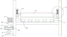
Fig. 1 is a schematic structural diagram of the present invention;
fig. 2 is a schematic front view of the present invention;
fig. 3 is an enlarged view of a in fig. 2.
Reference numerals: 1. a clamping plate; 2. a servo motor; 3. preheating a fan; 4. a heating box; 5. a preheating pipe; 6. mounting a plate; 7. a first connecting rod; 8. a second connecting rod; 9. a roller; 10. a slider; 11. a spring; 12. a fixed block; 13. an air outlet pipe; 14. an air supply hose; 15. an electric heating wire; 16. a hot gas exhaust nozzle; 17. and (7) fixing the plate.
Detailed Description
The technical solutions in the embodiments of the present invention will be described clearly and completely with reference to the accompanying drawings in the embodiments of the present invention, and it is obvious that the described embodiments are only some embodiments of the present invention, not all embodiments. Based on the embodiments in the present invention, all other embodiments obtained by a person skilled in the art without creative work belong to the protection scope of the present invention.
Examples
Referring to fig. 1 to 3, a compounding machine of preheating mechanism, including grip block 1, grip block 1 is equipped with two sets ofly, servo motor 2 and preheating fan 3 are installed to a set of grip block 1 one side, be connected with fixture on the servo motor 2, fixture installs between two sets of grip blocks 1, heating cabinet 4 is installed to preheating fan 3 upper end, be equipped with out tuber pipe 13 on preheating fan 3, it sets up in heating cabinet 4 to go out tuber pipe 13, the upper end of heating cabinet 4 is equipped with air supply hose 14, be connected with preheating tube 5 on the air supply hose 14, preheating tube 5 fixed mounting is between two sets of grip blocks 1.
Referring to fig. 1, since the mounting plate 6 is fixedly mounted on one side of the group of clamping plates 1, and the servo motor 2 is fixedly mounted on the upper end of the mounting plate 6, the mounting plate 6 can fixedly mount the servo motor 2.
Referring to fig. 2, because fixture includes head rod 7 and second connecting rod 8, the output of servo motor 2 passes through the shaft coupling and is connected with head rod 7, the equal fixed mounting of head rod 7 and second connecting rod 8 is between two sets of grip blocks 1, the head rod 7 all is equipped with running roller 9 with the second connecting rod 8 outside, the laminating of two sets of running roller 9 curved surfaces, so servo motor 2 drives head rod 7 and rotates, running roller 9 can carry out the centre gripping transportation to the material.
Referring to fig. 3, because second connecting rod 8 both ends are connected with slider 10, slider 10 all cup joints on the slide bar, slider 10 upper end all is equipped with spring 11, the slide bar both ends are through fixed block 12 fixed mounting on grip block 1, so when carrying out the centre gripping to the material, spring 11 extrudees slider 10, slider 10 slides on the slide bar, slider 10 drives second connecting rod 8 and reciprocates, can be to the better centre gripping that carries on of material of different thickness.
Referring to fig. 2, since the heating wire 15 is fixedly installed in the heating box 4, the heating wire 15 can heat cold air.
Referring to fig. 2, since the preheating pipe 5 is provided with a plurality of hot gas exhaust nozzles 16, the hot gas exhaust nozzles 16 facilitate the exhaust of hot gas.
Referring to fig. 2, since the fixing plate 17 is fixedly installed on one side of the group of clamping plates 1, and the preheating fan 3 is fixedly installed on the upper end of the fixing plate 17, the fixing plate 17 is convenient for installing and fixing the preheating fan 3.
The use principle and the advantages are as follows:
this preheating machine constructs's compounding machine has the material heating that can adapt to different thickness, improve equipment's utilization ratio, reduce the appearance probability of waste product, this preheating machine constructs's compounding machine is equipped with preheating fan 3 and heating cabinet 4, can heat the material and be convenient for paper and mould compound, servo motor 2 drives fixture and carries out the centre gripping transportation to the material, when carrying out the centre gripping to the material, spring 11 extrudees slider 10, slider 10 slides on the slide bar, slider 10 drives second connecting rod 8 and reciprocates, can be the better centre gripping that carries out of material to different thickness, preheating fan 3 blows off hot-blastly through heating cabinet 4, blow off hot-blastly through preheating pipe 5 after that, hot-blastly can make the paper mould to paste more firm between the composite bed with the material heating, and make the dry speed of back of pasting accelerate.
Although embodiments of the present invention have been shown and described, it will be appreciated by those skilled in the art that changes, modifications, substitutions and alterations can be made in these embodiments without departing from the principles and spirit of the invention, the scope of which is defined in the appended claims and their equivalents.
Claims (7)
1. The utility model provides a compounding machine of preheating machine constructs, includes grip block (1), its characterized in that: the utility model discloses a preheating device, including clamping plate (1), servo motor (2) and preheating fan (3) are installed to clamping plate (1) and are equipped with two sets ofly, and is a set of one side of clamping plate (1), be connected with fixture on servo motor (2), fixture installs two sets ofly between clamping plate (1), preheating fan (3) upper end is equipped with heating cabinet (4), be equipped with out tuber pipe (13) on preheating fan (3), it is in to go out tuber pipe (13) setting in heating cabinet (4), heating cabinet (4) upper end is equipped with air supply hose (14), be connected with preheating tube (5) on air supply hose (14), preheating tube (5) fixed mounting is two sets ofly between clamping plate (1).
2. The compound machine of the preheating mechanism as claimed in claim 1, wherein: a set of grip block (1) one side fixed mounting has mounting panel (6), servo motor (2) fixed mounting be in mounting panel (6) upper end.
3. The compound machine of the preheating mechanism as claimed in claim 1, wherein: fixture includes head rod (7) and second connecting rod (8), servo motor (2) output pass through the shaft coupling with head rod (7) are connected, head rod (7) with the equal fixed mounting of second connecting rod (8) is two sets of between grip block (1), head rod (7) with the second connecting rod (8) outside all is equipped with running roller (9), and is two sets of running roller (9) curved surface laminating.
4. A laminating machine with a preheating mechanism according to claim 3, characterized in that: the two ends of the second connecting rod (8) are connected with sliding blocks (10), the sliding blocks (10) are all sleeved on the sliding rods, springs (11) are arranged at the upper ends of the sliding blocks (10), and the two ends of each sliding rod are fixedly installed on the clamping plate (1) through fixing blocks (12).
5. The compound machine of the preheating mechanism as claimed in claim 1, wherein: and an electric heating wire (15) is fixedly arranged in the heating box (4).
6. The compound machine of the preheating mechanism as claimed in claim 1, wherein: and a plurality of hot gas exhaust nozzles (16) are arranged on the preheating pipe (5).
7. The compound machine of the preheating mechanism as claimed in claim 1, wherein: and one side of the clamping plate (1) is fixedly provided with a fixing plate (17), and the preheating fan (3) is fixedly arranged at the upper end of the fixing plate (17).
Priority Applications (1)
| Application Number | Priority Date | Filing Date | Title |
|---|---|---|---|
| CN202121410071.0U CN214774602U (en) | 2021-06-24 | 2021-06-24 | Compounding machine of preheating mechanism |
Applications Claiming Priority (1)
| Application Number | Priority Date | Filing Date | Title |
|---|---|---|---|
| CN202121410071.0U CN214774602U (en) | 2021-06-24 | 2021-06-24 | Compounding machine of preheating mechanism |
Publications (1)
| Publication Number | Publication Date |
|---|---|
| CN214774602U true CN214774602U (en) | 2021-11-19 |
Family
ID=78714516
Family Applications (1)
| Application Number | Title | Priority Date | Filing Date |
|---|---|---|---|
| CN202121410071.0U Active CN214774602U (en) | 2021-06-24 | 2021-06-24 | Compounding machine of preheating mechanism |
Country Status (1)
| Country | Link |
|---|---|
| CN (1) | CN214774602U (en) |
Cited By (1)
| Publication number | Priority date | Publication date | Assignee | Title |
|---|---|---|---|---|
| CN115654886A (en) * | 2022-10-28 | 2023-01-31 | 江苏晶杰光电科技有限公司 | Quick drying device is used in wafer processing |
-
2021
- 2021-06-24 CN CN202121410071.0U patent/CN214774602U/en active Active
Cited By (2)
| Publication number | Priority date | Publication date | Assignee | Title |
|---|---|---|---|---|
| CN115654886A (en) * | 2022-10-28 | 2023-01-31 | 江苏晶杰光电科技有限公司 | Quick drying device is used in wafer processing |
| CN115654886B (en) * | 2022-10-28 | 2023-08-22 | 江苏晶杰光电科技有限公司 | Quick drying device is used in wafer processing |
Similar Documents
| Publication | Publication Date | Title |
|---|---|---|
| CN106739452B (en) | A kind of transfer of wall paper, Embossing processing system | |
| CN206475555U (en) | Aluminium sheet film covering device | |
| CN203739368U (en) | Film laminator of rock wool board | |
| CN214774602U (en) | Compounding machine of preheating mechanism | |
| WO2010139126A1 (en) | Coating machine | |
| CN214288945U (en) | Double-gluing device of coating compound machine | |
| CN102689486A (en) | Energy-saving laminating machine | |
| CN204414693U (en) | A kind of production equipment of heat insulation clad metal sheet | |
| CN206426642U (en) | It is a kind of that there is the gilding press for cutting out mechanism | |
| CN207549607U (en) | A kind of sizing of compound fluting medium and drying system | |
| CN109878191A (en) | A kind of three layers of compounding machine of Alternative integrated synchronous | |
| CN210733522U (en) | Adhesive sticker production device | |
| CN206796749U (en) | Novel compounding machine | |
| CN207630697U (en) | A kind of novel Film laminated device | |
| CN206633555U (en) | A kind of compound hot-press arrangement of KT plates | |
| CN206124452U (en) | Seal back tectorial membrane fine processing equipment | |
| CN211491970U (en) | Hot rolling device for fiber board | |
| KR960010138B1 (en) | Manufacturing equipment for aluminium sandwich panel | |
| CN214027273U (en) | Automatic laminating machine of EPE piece | |
| CN212684962U (en) | Cloth laminating machine | |
| CN210590946U (en) | Special reflecting layer production system for long-distance heat transmission network | |
| CN207643865U (en) | A kind of adhesive sticker sheet material specific complex machine | |
| CN113601945A (en) | Hot melt film bonding composite equipment and composite method thereof | |
| CN213533856U (en) | Transfer base film production system | |
| CN219214384U (en) | Carbon-silicon composite material thermal cladding machine |
Legal Events
| Date | Code | Title | Description |
|---|---|---|---|
| GR01 | Patent grant | ||
| GR01 | Patent grant |