CN214773596U - Quick demoulding's mould - Google Patents
Quick demoulding's mould Download PDFInfo
- Publication number
- CN214773596U CN214773596U CN202022784105.4U CN202022784105U CN214773596U CN 214773596 U CN214773596 U CN 214773596U CN 202022784105 U CN202022784105 U CN 202022784105U CN 214773596 U CN214773596 U CN 214773596U
- Authority
- CN
- China
- Prior art keywords
- driving device
- die
- lifting driving
- mold
- base
- Prior art date
- Legal status (The legal status is an assumption and is not a legal conclusion. Google has not performed a legal analysis and makes no representation as to the accuracy of the status listed.)
- Active
Links
Images

Landscapes
- Moulds For Moulding Plastics Or The Like (AREA)
Abstract
The utility model discloses a fast demoulding mould, which comprises a base, an injection moulding production line, a demoulding mechanism and an injection moulding device; elastic supporting frames are arranged at the tops of the two sides of the base; the injection molding production line is positioned above the base; the demoulding mechanism comprises a first lifting driving device, a second lifting driving device and a demoulding rod; the first lifting driving device is arranged at the bottom of the injection molding production line; the second lifting driving device is arranged on the base; the demoulding rod is arranged at the top of the driving end of the second lifting driving device; the injection molding device comprises a top mold and a bottom mold; the top die is arranged at the bottom of the driving end of the first lifting driving device; the bottom die is arranged at the top of the elastic support frame, and the top die and the bottom die can surround to form a die cavity; a sliding hole communicated with the mold cavity is arranged in the bottom mold; the top of the demoulding rod is arranged in the sliding hole in a sliding way. The utility model discloses can make stripper bar and product separation automatically, need not rely on external force again behind the ejecting product of stripper bar to break away from stripper bar and product, labour saving and time saving.
Description
Technical Field
The utility model belongs to the technical field of belong to injection mold, concretely relates to quick drawing of patterns's mould.
Background
An injection mold is a tool for producing plastic products; and is also a tool for giving the plastic product complete structure and accurate dimension. Injection molding is a process used to mass produce parts of some complex shapes. Specifically, the plastic melted by heating is injected into a mold cavity from an injection molding machine at high pressure, and a formed product is obtained after cooling and solidification.
According to the existing injection mold, because the demolding rod is in contact with a melted raw material during injection molding, the top of the demolding rod is bonded with a product after the product is molded, and the product is separated from the demolding rod by means of external force after the product is ejected by the demolding rod, so that the existing injection mold is very inconvenient.
SUMMERY OF THE UTILITY MODEL
The utility model provides a solve above-mentioned technical problem and provide a mould of fast demoulding.
The utility model discloses a realize its technological effect and the solution that adopts does:
a fast demoulding mould comprises a base, an injection moulding production line, a demoulding mechanism and an injection moulding device; elastic supporting frames are arranged at the tops of the two sides of the base; the injection molding production line is positioned above the base; the demolding mechanism comprises a first lifting driving device, a second lifting driving device and a demolding rod; the first lifting driving device is arranged at the bottom of the injection molding production line; the second lifting driving device is arranged on the base; the demolding rod is arranged at the top of the driving end of the second lifting driving device; the injection molding device comprises a top mold and a bottom mold; the top die is arranged at the bottom of the driving end of the first lifting driving device; the bottom die is arranged at the top of the elastic support frame, and the top die and the bottom die can surround to form a die cavity; a sliding hole communicated with the mold cavity is formed in the bottom mold; the top of the demoulding rod is arranged in the sliding hole in a sliding mode.
Preferably, two sides of the top of the base are provided with supporting seats; a concave groove is formed in the supporting seat; the concave groove is provided with an installation cavity; the elastic support frame comprises a support column and a spring; the spring is arranged in the mounting cavity; the support column is arranged at the bottom of the bottom die; the bottom of the supporting column extends into the mounting cavity in a sliding mode and is arranged at the top of the spring in a pressing mode.
Preferably, the bottom of the top die is provided with a positioning column; the top of the bottom die is provided with a positioning hole; the positioning column is arranged in the positioning hole in a sliding mode.
The utility model has the advantages that: the bottom die is supported by the elastic support frame, and when the first lifting driving device drives the top die to press down and match the bottom die, the bottom die is pressed down elastically, so that the top of the demolding rod moves upwards relatively to block the bottom of the mold cavity; when the injection molding is finished and the demolding is needed, the first lifting driving device drives the top mold to move upwards, the bottom mold automatically moves upwards under the action of the elastic supporting frame, the demolding rod automatically separates from the product, and finally the second lifting driving device drives the demolding rod to move upwards to eject the product out of the mold. Therefore, the utility model discloses can make stripper bar and product separation automatically, need not rely on external force again behind the ejecting product of stripper bar to break away from stripper bar and product, labour saving and time saving.
Drawings
Fig. 1 is a schematic front view of a mold disclosed in an embodiment of the present invention;
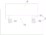
fig. 2 is a schematic view of a supporting seat and an elastic supporting frame according to an embodiment of the present invention.
And (3) identification and explanation: 1-base, 2-injection molding production line, 3-elastic support frame, 31-support column, 32-spring, 4-first lifting driving device, 5-second lifting driving device, 6-demoulding rod, 7-top mould, 8-bottom mould, 9-sliding hole, 10-support seat, 11-concave groove, 12-installation cavity, 13-positioning column and 14-positioning hole.
Detailed Description
In order to make the objects, technical solutions and advantages of the present invention more clearly understood, the present invention is further described in detail below with reference to the accompanying drawings and embodiments. It should be understood that the specific embodiments described herein are merely illustrative of the invention and are not intended to limit the invention. It will be understood that when an element is referred to as being "secured to" or "disposed on" another element, it can be directly on the other element or intervening elements may also be present. When an element is referred to as being "connected" to another element, it can be directly connected to the other element or intervening elements may also be present. When one element is referred to as being "fixedly attached" to another element, it can be fixedly attached by welding, bolting, gluing, or the like.
Referring to fig. 1-2, in a preferred embodiment of the present invention, a mold for rapid demolding is disclosed, which includes a base 1, an injection molding line 2, a demolding mechanism and an injection molding device; elastic support frames 3 are arranged at the tops of two sides of the base 1; the injection molding production line 2 is positioned above the base 1; the demoulding mechanism comprises a first lifting driving device 4, a second lifting driving device 5 and a demoulding rod 6; the first lifting driving device 4 is arranged at the bottom of the injection molding production line 2; the second lifting driving device 5 is arranged on the base 1; the demoulding rod 6 is arranged at the top of the driving end of the second lifting driving device 5; the injection molding device comprises a top mold 7 and a bottom mold 8; the top die 7 is arranged at the bottom of the driving end of the first lifting driving device 4; the bottom die 8 is arranged at the top of the elastic support frame 3, and the top die 7 and the bottom die 8 can surround to form a die cavity; a sliding hole 9 communicated with the mold cavity is formed in the bottom mold 8; the top of the demoulding rod 6 is arranged in the sliding hole 9 in a sliding way.
Specifically, two sides of the top of the base 1 are provided with supporting seats 10; a concave groove 11 is arranged on the supporting seat 10; the concave groove 11 is provided with an installation cavity 12; the elastic support frame 3 comprises a support column 31 and a spring 32; the spring 32 is arranged in the mounting cavity 12; the supporting column 31 is arranged at the bottom of the bottom die 8; the bottom of the supporting column 31 is slidably extended into the mounting cavity 12 and is pressed on the top of the spring 31. The bottom die 8 moves downwards under the pressure of the top die 7 and is finally pressed in the concave groove 11, so that the bottom die 8 is prevented from shaking in the injection molding process, and the quality of a product is prevented from being adversely affected. In particular, when the bottom mold 8 is pressed against the top of the recess 11, the top of the ejector rod 6 just needs to be in contact with the top of the mold cavity.
Specifically, a positioning column 13 is arranged at the bottom of the top die 7; a positioning hole 14 is formed in the top of the bottom die 8; the positioning column 13 is slidably disposed in the positioning hole 14. The positioning columns 13 and the positioning holes 14 can effectively ensure that the top die 7 and the bottom die 8 are quickly and accurately matched.
Specifically, the first lifting driving device 4 and the second lifting driving device 5 are both air cylinders.
According to the above description, the utility model discloses can make the product fast drawing of patterns voluntarily, labour saving and time saving.
While the preferred embodiments of the present invention have been illustrated in detail in the accompanying drawings, it should be understood that the scope of the invention includes, but is not limited to, the embodiments described above; the specific structure disclosed in the drawings is only a preferred embodiment of the present invention, and those skilled in the art can also develop other embodiments on this basis, and any simple deformation or equivalent replacement without departing from the innovative concept of the present invention is covered by the present invention, which belongs to the protection scope of the present invention.
Claims (3)
1. A mold for rapid prototyping, comprising:
a base; elastic supporting frames are arranged at the tops of the two sides of the base;
an injection molding production line; the injection molding production line is positioned above the base;
a demolding mechanism; the demolding mechanism comprises a first lifting driving device, a second lifting driving device and a demolding rod; the first lifting driving device is arranged at the bottom of the injection molding production line; the second lifting driving device is arranged on the base; the demolding rod is arranged at the top of the driving end of the second lifting driving device;
an injection molding device; the injection molding device comprises a top mold and a bottom mold; the top die is arranged at the bottom of the driving end of the first lifting driving device; the bottom die is arranged at the top of the elastic support frame, and the top die and the bottom die can surround to form a die cavity; a sliding hole communicated with the mold cavity is formed in the bottom mold; the top of the demoulding rod is arranged in the sliding hole in a sliding mode.
2. The rapid-release mold according to claim 1, wherein: supporting seats are arranged on two sides of the top of the base; a concave groove is formed in the supporting seat; the concave groove is provided with an installation cavity; the elastic support frame comprises a support column and a spring; the spring is arranged in the mounting cavity; the support column is arranged at the bottom of the bottom die; the bottom of the supporting column extends into the mounting cavity in a sliding mode and is arranged at the top of the spring in a pressing mode.
3. The rapid-release mold according to claim 1, wherein: the bottom of the top die is provided with a positioning column; the top of the bottom die is provided with a positioning hole; the positioning column is arranged in the positioning hole in a sliding mode.
Priority Applications (1)
| Application Number | Priority Date | Filing Date | Title |
|---|---|---|---|
| CN202022784105.4U CN214773596U (en) | 2020-11-26 | 2020-11-26 | Quick demoulding's mould |
Applications Claiming Priority (1)
| Application Number | Priority Date | Filing Date | Title |
|---|---|---|---|
| CN202022784105.4U CN214773596U (en) | 2020-11-26 | 2020-11-26 | Quick demoulding's mould |
Publications (1)
| Publication Number | Publication Date |
|---|---|
| CN214773596U true CN214773596U (en) | 2021-11-19 |
Family
ID=78709883
Family Applications (1)
| Application Number | Title | Priority Date | Filing Date |
|---|---|---|---|
| CN202022784105.4U Active CN214773596U (en) | 2020-11-26 | 2020-11-26 | Quick demoulding's mould |
Country Status (1)
| Country | Link |
|---|---|
| CN (1) | CN214773596U (en) |
-
2020
- 2020-11-26 CN CN202022784105.4U patent/CN214773596U/en active Active
Similar Documents
| Publication | Publication Date | Title |
|---|---|---|
| CN212072600U (en) | Mould with novel ejection mechanism | |
| CN212045728U (en) | Multi-cavity optical lens injection mold | |
| CN212045827U (en) | Step-by-step molding optical lens injection mold | |
| CN214773596U (en) | Quick demoulding's mould | |
| CN201287445Y (en) | Mould | |
| CN209577853U (en) | A kind of cutting mould of auto-parts processing | |
| CN213891041U (en) | Automatic drawing of patterns and safe mould of drawing of patterns process | |
| CN216683193U (en) | Demoulding mechanism for precise plastic mould | |
| CN213891040U (en) | Injection mold of curved surface injection molding | |
| CN213533600U (en) | Mould structure for controlling warping of thin-wall plastic part | |
| CN220763369U (en) | Injection mold with annular cooling mechanism for plastic feeding bottle box of children | |
| CN221339426U (en) | Improve mould structure of thimble seal impression | |
| CN112976496B (en) | Injection molding mould of high quality drawing of patterns | |
| CN221605055U (en) | Structure suitable for rear mold inside oblique drawing insert | |
| CN215550597U (en) | Mould forming structure of automobile shell part | |
| CN220883246U (en) | Automatic ejection structure of die | |
| CN213137628U (en) | Upper die driving device convenient for feeding and discharging | |
| CN212312664U (en) | Plastic product forming die | |
| CN211363278U (en) | Injection mold convenient to ejection of compact | |
| CN221475993U (en) | Injection mold convenient to quick drawing of patterns | |
| CN214605636U (en) | Injection mold for vehicle-mounted built-in storage box | |
| CN214448183U (en) | But injection mold of quick replacement activity insert piece | |
| CN211917582U (en) | Injection mold for processing wheat sheath | |
| CN220464629U (en) | Injection mold convenient to demolding | |
| CN207509617U (en) | The precise injection mould of scan camera shooting camera lens |
Legal Events
| Date | Code | Title | Description |
|---|---|---|---|
| GR01 | Patent grant | ||
| GR01 | Patent grant |