CN214687610U - Water gap material recycling system - Google Patents
Water gap material recycling system Download PDFInfo
- Publication number
- CN214687610U CN214687610U CN202023351285.3U CN202023351285U CN214687610U CN 214687610 U CN214687610 U CN 214687610U CN 202023351285 U CN202023351285 U CN 202023351285U CN 214687610 U CN214687610 U CN 214687610U
- Authority
- CN
- China
- Prior art keywords
- recycling system
- mouth
- filter
- injection molding
- molding machine
- Prior art date
- Legal status (The legal status is an assumption and is not a legal conclusion. Google has not performed a legal analysis and makes no representation as to the accuracy of the status listed.)
- Active
Links
Images

Classifications
-
- Y—GENERAL TAGGING OF NEW TECHNOLOGICAL DEVELOPMENTS; GENERAL TAGGING OF CROSS-SECTIONAL TECHNOLOGIES SPANNING OVER SEVERAL SECTIONS OF THE IPC; TECHNICAL SUBJECTS COVERED BY FORMER USPC CROSS-REFERENCE ART COLLECTIONS [XRACs] AND DIGESTS
- Y02—TECHNOLOGIES OR APPLICATIONS FOR MITIGATION OR ADAPTATION AGAINST CLIMATE CHANGE
- Y02W—CLIMATE CHANGE MITIGATION TECHNOLOGIES RELATED TO WASTEWATER TREATMENT OR WASTE MANAGEMENT
- Y02W30/00—Technologies for solid waste management
- Y02W30/50—Reuse, recycling or recovery technologies
- Y02W30/52—Mechanical processing of waste for the recovery of materials, e.g. crushing, shredding, separation or disassembly
-
- Y—GENERAL TAGGING OF NEW TECHNOLOGICAL DEVELOPMENTS; GENERAL TAGGING OF CROSS-SECTIONAL TECHNOLOGIES SPANNING OVER SEVERAL SECTIONS OF THE IPC; TECHNICAL SUBJECTS COVERED BY FORMER USPC CROSS-REFERENCE ART COLLECTIONS [XRACs] AND DIGESTS
- Y02—TECHNOLOGIES OR APPLICATIONS FOR MITIGATION OR ADAPTATION AGAINST CLIMATE CHANGE
- Y02W—CLIMATE CHANGE MITIGATION TECHNOLOGIES RELATED TO WASTEWATER TREATMENT OR WASTE MANAGEMENT
- Y02W30/00—Technologies for solid waste management
- Y02W30/50—Reuse, recycling or recovery technologies
- Y02W30/62—Plastics recycling; Rubber recycling
Landscapes
- Cyclones (AREA)
- Combined Means For Separation Of Solids (AREA)
Abstract
The utility model discloses a mouth of a river material recycling system, including injection molding machine, rubbing crusher, be used for taking out the manipulator and the head tank of putting into rubbing crusher with mouth of a river material from the injection molding machine mould, rubbing crusher has cyclone through the pipe connection, cyclone docks a filter tube, the collecting pipe is connected to the filter tube other end, collecting pipe and head tank are connected to the injection molding machine through a compounding device, be equipped with the filter screen in the filter tube, the filter screen blocks that large granule mouth of a river material gets into the collecting pipe. This system filters through twice separation, avoids dust and large granule mouth of a river material and raw materials to mix, can enough avoid the material extravagant, ensures the finished product's of moulding plastics quality again.
Description
Technical Field
The utility model belongs to the technical field of injection moulding equipment, more specifically say, relate to a mouth of a river material recycling system.
Background
CN 208052357U discloses a nozzle material recovery system, which comprises a crusher for crushing the nozzle material recovered from the injection molding machine; a raw material box for placing raw materials; the proportional mixing device can adjust the proportion of the water gap material and the raw material according to the setting, and is provided with two inlets which are respectively communicated with the raw material box through a pipeline and the crusher; the drying machine is used for drying the mixed water gap material and the raw material discharged from the proportional mixing device; the proportional mixing device is provided with a discharge port which is communicated with the dryer through a pipeline; and the drying machine conveys the dried water gap material and the raw material into the charging box through a pipeline, and the charging box is used by the forming machine.
The problem that above-mentioned mouth of a river material recovery system exists lies in, when smashing, the condition that can appear smashing uneven sometimes, leads to the large granule mouth of a river material to appear, can't separate the large granule mouth of a river material through cyclone, can make the finished product quality that moulds plastics out at last of preparation influenced.
Therefore, the technical problems to be solved by the application are as follows: how to avoid the large granule mouth of a river material to get into the charging box.
SUMMERY OF THE UTILITY MODEL
The utility model discloses a main aim at provides a mouth of a river material recovery system of recycling, this system filters through twice separation, avoids dust and large granule mouth of a river material to mix with the raw materials, can enough avoid the material extravagant, ensures the off-the-shelf quality of moulding plastics again.
According to the utility model discloses an aspect provides a mouth of a river material recycling system, including injection molding machine, rubbing crusher, be used for taking out the mouth of a river material from injection molding machine mould and put into manipulator, head tank of rubbing crusher, rubbing crusher has cyclone through the pipe connection, cyclone docks a filter tube, the collecting pipe is connected to the filter tube other end, collecting pipe and head tank are connected to the injection molding machine through a compounding device, be equipped with the filter screen in the filter tube, the filter screen blocks that large granule mouth of a river material gets into the collecting pipe.
The utility model discloses a specific embodiment, the vertical butt joint cyclone of filter tube, the filter screen is perpendicular with filter tube pan feeding direction.
In a specific embodiment of the present invention, the filtering tube is provided with a material taking opening for taking out the filtering net, and the material taking opening is provided with a cover plate.
In a particular embodiment of the present invention, the filter mesh tape is magnetic.
In a specific embodiment of the present invention, a blower is disposed on the pipeline connecting the pulverizer and the cyclone, and the blower blows the pulverized material to the cyclone.
The utility model discloses a specific embodiment, cyclone comprises cylinder and cone, the cylinder top is equipped with the filter core, the cone below is equipped with the discharge gate, the discharge gate docks with the filter tube, the discharge gate opens and shuts through first valve control, the pipeline is connected with cyclone's cylinder tangential.
In a specific embodiment of the present invention, an evacuation port is further disposed below the cone.
The utility model discloses a specific embodiment, be equipped with two input ports and an delivery outlet on the compounding device, material collecting pipe and head tank are connected respectively to two input ports, the injection molding machine is connected to the delivery outlet.
In a specific embodiment of the present invention, a second valve is provided in the mixing device, and the second valve adjusts the mixing ratio by controlling the opening degree of the two input ports.
The utility model discloses a technical scheme has following advantage or one of beneficial effect at least among the above-mentioned technical scheme:
this system of recycling is expected to mouth of a river takes out the mouth of a river material from the injection molding machine through the manipulator and puts into rubbing crusher again, and mouth of a river material is carried to cyclone dust removal after rubbing crusher smashes, and the rethread filter tube is through filter screen separation large granule mouth of a river material, and remaining mouth of a river material granule reachs the collecting tube, and rethread material mixing device mixes with the raw materials and gets into the injection molding machine, has avoided dust and large granule mouth of a river material to mix with the raw materials, can enough avoid the material extravagant, ensures the off-the-shelf quality of moulding plastics again.
Drawings
The present invention will be further described with reference to the accompanying drawings and examples;
fig. 1 is a schematic structural view of a nozzle material recycling system according to a first embodiment of the present invention;
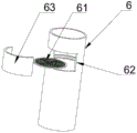
fig. 2 is a schematic structural view of a filter tube of a nozzle material recycling system according to a first embodiment of the present invention.
Detailed Description
Reference will now be made in detail to embodiments of the present invention, examples of which are illustrated in the accompanying drawings, wherein like or similar reference numerals refer to the same or similar elements or elements having the same or similar function throughout. The embodiments described below with reference to the accompanying drawings are exemplary only for the purpose of explaining the present invention, and should not be construed as limiting the present invention.
In the description of the present invention, it should be understood that the orientation or positional relationship indicated with respect to the orientation description, such as up, down, front, rear, left, right, etc., is based on the orientation or positional relationship shown in the drawings, and is only for convenience of description and simplification of description, and does not indicate or imply that the device or element referred to must have a specific orientation, be constructed and operated in a specific orientation, and thus, should not be construed as limiting the present invention.
In the description of the present invention, a plurality of means are one or more, a plurality of means are two or more, and the terms greater than, less than, exceeding, etc. are understood as not including the number, and the terms greater than, less than, within, etc. are understood as including the number. If the first and second are described for the purpose of distinguishing technical features, they are not to be understood as indicating or implying relative importance or implicitly indicating the number of technical features indicated or implicitly indicating the precedence of the technical features indicated.
Furthermore, the terms "first", "second" and "first" are used for descriptive purposes only and are not to be construed as indicating or implying relative importance or implicitly indicating the number of technical features indicated. Thus, a feature defined as "first" or "second" may explicitly or implicitly include one or more features.
In the description of the present invention, it is to be noted that, unless otherwise explicitly specified or limited, the term "connected" is to be interpreted broadly, and may be, for example, a fixed connection or a movable connection, a detachable connection or a non-detachable connection, or an integral connection; may be mechanically connected, may be electrically connected or may be in communication with each other; they may be directly connected or indirectly connected through intervening media, or may be connected through one or more other elements or indirectly connected through one or more other elements or in an interactive relationship between two elements.
The following disclosure provides many different embodiments or examples for implementing different aspects of the invention.
As shown with reference to figures 1 to 2,
the utility model discloses an embodiment, a mouth of a river material recycling system, including injection molding machine 1, rubbing crusher 2, be used for taking out the mouth of a river material from injection molding machine 1 mould and put into manipulator 3, head tank 4 of rubbing crusher 2, rubbing crusher 2 has cyclone 5 through the pipe connection, cyclone 5 docks a filter tube 6, collection material pipe 7 is connected to the filter tube 6 other end, collection material pipe 7 and head tank 4 are connected to injection molding machine 1 through a compounding device 8, be equipped with filter screen 61 in the filter tube 6, filter screen 61 blocks the large granule mouth of a river material and gets into collection material pipe 7.
The running mode of the water gap material recycling system is as follows: the mouth of a river material is taken out from injection molding machine 1 through manipulator 3 and is put into rubbing crusher 2 again, and mouth of a river material is carried to cyclone 5 after 2 smashes and is removed dust through rubbing crusher, and rethread filter tube 6 separates the large granule mouth of a river material through filter screen 61, and remaining mouth of a river material granule reachs collecting tube 7, and rethread material mixing device 8 mixes with the raw materials and gets into injection molding machine 1, has avoided dust and large granule mouth of a river material to mix with the raw materials, can enough avoid the material extravagant, ensures the off-the-shelf quality of moulding plastics again.
In a specific embodiment, the filter pipe 6 is vertically butted with the cyclone 5, and the filter screen 61 is perpendicular to the feeding direction of the filter pipe 6, so as to facilitate the falling of the nozzle material particles for filtering, of course, the filter pipe 6 may not be vertically butted with the cyclone 5, which is not limited in this embodiment.
The utility model discloses an embodiment, be equipped with the material taking port 62 that can take out filter screen 61 on the filter tube 6, be equipped with apron 63 on the material taking port 62, apron 63 covers material taking port 62 when the operation, does not let mouth of a river material granule reveal, when operation after a period, can open apron 63 and take out filter screen 61, will stay the big granule mouth of a river material above and fall rubbing crusher 2 back, smash once more, continue recycle.
Preferably, the filter screen 61 has magnetism, can adsorb iron fillings impurity mixed in the mouth of a river material granule, does not let it get into the collecting pipe 7, further guarantees the finished product quality of moulding plastics.
The utility model discloses an embodiment, be equipped with air-blower 21 on the pipeline that rubbing crusher 2 and cyclone 5 are connected, air-blower 21 blows the mouth of a river material granule that forms after 2 smashes rubbing crusher to cyclone 5.
The utility model discloses an embodiment, cyclone 5 comprises cylinder 51 and cone 52, cylinder 51 top is equipped with filter core 53, the cone below is equipped with discharge gate 54, discharge gate 54 docks with filter tube 6, discharge gate 54 opens and shuts through first valve 55 control, the pipeline is connected with cyclone 5's cylinder 51 tangential. The nozzle material particles enter the cylinder 51 tangentially along with the air flow, the nozzle material particles rotate along the wall of the cylinder 51 and fall through the wall of the cone 52 to reach the discharge hole 54, the air flow carries dust upwards to pass through the filter element 53 due to centrifugal force and then is discharged, and the dust is adsorbed on the filter element 53, so that the dust is separated.
In an embodiment of the present invention, a drain 56 is further disposed below the cone 52, which is beneficial to draining liquid during cleaning.
The utility model discloses an embodiment, be equipped with two input ports 81 and an delivery outlet 82 on the compounding device 8, collecting pipe 7 and head tank 4 are connected respectively to two input ports 81, injection molding machine 1 is connected to delivery outlet 82, and mouth of a river material granule and raw materials mix through compounding device 8 and reentry injection molding machine 1.
The utility model discloses an embodiment, be equipped with second valve 83 in the compounding device 8, the second valve 83 adjusts the mixing proportion of mouth of a river material granule and raw materials through controlling two input ports 81 degrees of opening to this makes the finished product quality of moulding plastics not influenced.
While embodiments of the present invention have been shown and described, it will be understood by those of ordinary skill in the art that: various changes, modifications, substitutions and alterations can be made to the embodiments without departing from the principles and spirit of the invention, the scope of which is defined by the claims and their equivalents.
Claims (9)
1. The utility model provides a mouth of a river material recycling system, includes injection molding machine, rubbing crusher, is used for taking out the manipulator, the head tank of putting into rubbing crusher with mouth of a river material from the injection molding machine mould, rubbing crusher has cyclone through the pipe connection, cyclone butt joint filter tube, the collecting tube is connected to the filter tube other end, collecting tube and head tank are connected to the injection molding machine through a compounding device, its characterized in that, be equipped with the filter screen in the filter tube, the filter screen blocks that large granule mouth of a river material gets into the collecting tube.
2. The nozzle charge recycling system of claim 1, wherein the filter tube is vertically abutted to the cyclone dust collector, and the filter screen is perpendicular to the feeding direction of the filter tube.
3. The nozzle charge recycling system according to claim 1, wherein the filter tube is provided with a material taking port from which the filter screen can be taken out, and the material taking port is provided with a cover plate.
4. The nozzle charge recycling system of claim 1, wherein the screen belt is magnetic.
5. The nozzle charge recycling system of claim 1, wherein a blower is arranged on a pipeline connecting the crusher and the cyclone dust collector, and the blower blows the crushed nozzle charge to the cyclone dust collector.
6. The nozzle material recycling system according to claim 1, wherein the cyclone dust collector comprises a cylinder and a cone, a filter element is arranged above the cylinder, a discharge port is arranged below the cone, the discharge port is in butt joint with the filter pipe, the discharge port is controlled to open and close by a first valve, and the pipeline is tangentially connected with the cylinder of the cyclone dust collector.
7. The nozzle charge recycling system of claim 6, wherein a drain is further provided below the cone.
8. The nozzle material recycling system according to claim 1, wherein the mixing device is provided with two input ports and an output port, the two input ports are respectively connected with the material collecting pipe and the material tank, and the output port is connected with the injection molding machine.
9. The nozzle charge recycling system of claim 8, wherein a second valve is arranged in the mixing device, and the second valve adjusts the mixing ratio by controlling the opening degree of the two input ports.
Priority Applications (1)
| Application Number | Priority Date | Filing Date | Title |
|---|---|---|---|
| CN202023351285.3U CN214687610U (en) | 2020-12-31 | 2020-12-31 | Water gap material recycling system |
Applications Claiming Priority (1)
| Application Number | Priority Date | Filing Date | Title |
|---|---|---|---|
| CN202023351285.3U CN214687610U (en) | 2020-12-31 | 2020-12-31 | Water gap material recycling system |
Publications (1)
| Publication Number | Publication Date |
|---|---|
| CN214687610U true CN214687610U (en) | 2021-11-12 |
Family
ID=78561724
Family Applications (1)
| Application Number | Title | Priority Date | Filing Date |
|---|---|---|---|
| CN202023351285.3U Active CN214687610U (en) | 2020-12-31 | 2020-12-31 | Water gap material recycling system |
Country Status (1)
| Country | Link |
|---|---|
| CN (1) | CN214687610U (en) |
-
2020
- 2020-12-31 CN CN202023351285.3U patent/CN214687610U/en active Active
Similar Documents
| Publication | Publication Date | Title |
|---|---|---|
| CN207401560U (en) | Suitable for the reducing mechanism of textile raw material | |
| CN112916173B (en) | Catalyst crushing process | |
| CN108855349A (en) | A kind of automatically processing device for rice production rice flour technique | |
| CN107489050A (en) | A kind of paper pulp filtering structure in waste paper recycling and processing device | |
| CN214687610U (en) | Water gap material recycling system | |
| CN214811548U (en) | Novel catalyst is smashed superfine grinding for system device | |
| CN211964415U (en) | Separator and grinding equipment | |
| CN210758852U (en) | Plastic particle feeding hopper for plastic bottle production | |
| CN107837709A (en) | A kind of feed mixing and filtrating device | |
| CN205413278U (en) | Synchronous ball -milling device of stereoplasm raw materials | |
| CN211709884U (en) | Material suction machine for injection molding machine | |
| CN207996725U (en) | A kind of airslide disintegrating mill of Chinese medicinal preparation of children particle | |
| CN210733216U (en) | Single screw extruder of preparation plastics dewatering defoaming master batch | |
| CN209997760U (en) | combined recycling device for acid-leaching lead slime and cast-weld lead slag | |
| CN208543681U (en) | A kind of casting films edge recycling system | |
| CN208865749U (en) | A kind of air-flow crushing and conglomerate integration device of dyestuff | |
| CN209318172U (en) | A kind of Beer Brewage workshop malt recycle device | |
| CN206170517U (en) | Charging barrel for injection molding machine | |
| CN209318132U (en) | Separate grinding device and catalyst production equipment | |
| CN207121742U (en) | A kind of paper pulp filtering structure in waste paper recycling and processing device | |
| CN207980911U (en) | A kind of multi-stage separation feed mixing machine | |
| CN209649241U (en) | A kind of frame raw material drying device | |
| CN209254844U (en) | It is a kind of for processing the material tower of magnetic core | |
| CN208697900U (en) | A kind of insulation board extrusion equipment | |
| CN207121745U (en) | A kind of fiberizer in waste paper recycling and processing device |
Legal Events
| Date | Code | Title | Description |
|---|---|---|---|
| GR01 | Patent grant | ||
| GR01 | Patent grant |