CN214681891U - Dust extraction is processed to coarse rice - Google Patents
Dust extraction is processed to coarse rice Download PDFInfo
- Publication number
- CN214681891U CN214681891U CN202121218199.7U CN202121218199U CN214681891U CN 214681891 U CN214681891 U CN 214681891U CN 202121218199 U CN202121218199 U CN 202121218199U CN 214681891 U CN214681891 U CN 214681891U
- Authority
- CN
- China
- Prior art keywords
- dust
- dust removal
- fixed
- rice
- driving motor
- Prior art date
- Legal status (The legal status is an assumption and is not a legal conclusion. Google has not performed a legal analysis and makes no representation as to the accuracy of the status listed.)
- Active
Links
Images

Abstract
The utility model discloses a crude rice processing dust extraction relates to grain processing technology field. The utility model discloses a dust removal case, the left side of dust removal case is provided with the chamber door, and the intermediate position department of dust removal incasement side is provided with driving motor, and driving motor's power output shaft's the outside is provided with a plurality of dwangs, and driving motor's the inside that the below corresponds the dust removal case is provided with the filter sieve, and the lower wall of filter sieve is fixed with the bobbing machine, and the right wall of dust removal case is fixed with the air-blower, and the downside in the air-blower right side is provided with the water tank, and the inside of water tank is provided with liquid water. The utility model discloses a driving motor drives the dwang and rotates and applys the effort to the rice, makes the dust and the rice separation on rice surface, and mixes the dust to the inside and the liquid water of water tank through the air-blower, and it is relatively poor to have solved the dust removal effect when prior art utilizes the fan to remove dust, and prior art removes dust the back to the rice, and the dust is wafted aloft, produces the problem of great harm to staff's health.
Description
Technical Field
The utility model belongs to the technical field of grain processing, especially, relate to a crude rice processing dust extraction.
Background
Grain processing means to convert the raw grain into semi-finished grain, or convert semi-finished grain into finished grain, wherein, the rice is known as the first of five cereals, its nutrition is very abundant, account for 1/4 of grain crop cultivation area approximately, half population uses the rice as staple food in the world, the rice is formed through the processing of polished rice, when adding man-hour to polished rice, need carry out dust absorption to polished rice when adding man-hour usually, but it still has following drawback in the in-service use:
at present, when the rice processed is subjected to dust removal, a fan is generally used for generating air flow to remove dust, but the dust removal effect is poor when the fan is used for removing dust in the prior art;
after the rice is dedusted in the prior art, the dust is scattered in the air, and the damage to the health of workers is great.
Therefore, the dust removal effect is poor when the fan is used for removing dust in the prior art, and after the rice is removed, dust scatters in the air, great damage is caused to the health of workers, and the requirement in actual use cannot be met, so that an improved technology is urgently needed in the market to solve the problems.
SUMMERY OF THE UTILITY MODEL
An object of the utility model is to provide a gross rice processing dust extraction, drive the dwang through driving motor and rotate and apply the effort to the rice, make the dust and the rice separation on rice surface, and carry the inside and the liquid water mixture of dust to the water tank through the air-blower, it is relatively poor to have solved the dust removal effect when prior art utilizes the fan to remove dust, and prior art removes dust the back to the rice, and the dust is wafted aloft, produces the problem of great harm to staff's health.
In order to solve the technical problem, the utility model discloses a realize through following technical scheme:
the utility model relates to a crude rice processing dust extraction, including the dust removal case, the left side of dust removal case is provided with the chamber door, the intermediate position department of dust removal incasement side is provided with driving motor, driving motor's power output shaft's the outside is provided with a plurality of dwangs, driving motor's the inside that the below corresponds the dust removal case is provided with the filter sieve, and the filter sieve uses magnetic filter sieve, the lower wall of filter sieve is fixed with the bobbing machine, the right wall of dust removal case is fixed with the air-blower, the downside in the air-blower right side is provided with the water tank, the inside of water tank is provided with liquid water, and the input of air-blower, driving motor and bobbing machine is all through conductor wire and external power source electric connection.
Further, the chamber door passes through the hinge and is connected with the dust removal case rotation, one side of the hinge of keeping away from of chamber door left wall is fixed with presses down the lock, feed inlet and discharge gate have been seted up to the top and the bottom of dust removal case correspondence respectively, and the feed inlet is located the left side of dust removal case upper wall.
Further, the inner wall that driving motor's top corresponds the dust removal case is fixed with the mounting panel, and the cross section of mounting panel sets up for T shape, driving motor fixes the lower surface at the mounting panel, be fixed with fixed cover on driving motor's the power output shaft, and the dwang is evenly fixed on the periphery wall of fixed cover, and the length of a plurality of dwangs is the same.
Further, the inner wall that corresponds the dust removal case in the top of filter sieve is fixed with the deflector, the inboard of deflector is cavity setting, and the horizontal plane of deflector outer end is higher than the horizontal plane of deflector inner, and the inboard and the filter sieve part of deflector overlap, the edgewise department of filtering the sieve upper wall is provided with the hem.
Further, four turning positions of the lower wall of the filter screen are all fixed with springs, the inner walls of the lower ends of the springs, corresponding to the dust removal box, are all fixed with fixing plates, the lower ends of the springs are fixed on the upper surfaces of the fixing plates, and the inner walls of the air inlet ends of the air blower, corresponding to the dust removal box, are fixed with screen meshes.
Furthermore, the air outlet end of the air blower is fixed with a connecting pipe, the other end of the connecting pipe is fixed on the side wall of the lower side of the water tank, the air outlet end of the air blower is communicated with the inside of the connecting pipe, the air inlet end of the air blower is communicated with the inside of the dust removal box, and the inside of the connecting pipe is communicated with the inside of the water tank.
The utility model discloses following beneficial effect has:
the utility model discloses a through setting up driving motor, the dwang, filter sieve and bobbing machine, when removing dust to the gross rice, switch on driving motor, the power of bobbing machine, can make the gross rice pass the feed inlet at the uniform velocity and get into the inside of dust removal case, driving motor during operation, driving motor's power output shaft rotates and drives the fixed cover rotation, then make the dwang rotate in order to exert the effort to the gross rice, make the dust of gross rice surface break away from with the gross rice, the gross rice after removing dust can drop to the filter sieve, under the effect of bobbing machine, the gross rice passes the filter sieve and arranges to the outside of dust removal case from the discharge gate, and when the gross rice passes the filter sieve, because the filter sieve has magnetism, can adsorb the iron impurity in the gross rice, avoid iron impurity to mix in the inside of gross rice, compare with prior art, make through driving motor work to rotate and carry out the dwang to the gross rice, make the dust break away from the surface of crude rice, promote the effect of dust removal, can adsorb the iron impurity in the crude rice through making the filter sieve simultaneously, the relatively poor problem of dust removal effect when having solved prior art and having utilized the fan to remove dust.
The utility model discloses a set up the air-blower, water tank and liquid water, when removing dust, air-blower work can carry the dust of dust removal incasement portion to the inside of connecting pipe, under the continuous effect of air-blower, the air that carries the dust passes the inside that liquid water breaks away from the water tank, and the dust then mixes with liquid water, compared with the prior art, carry the dust of dust removal incasement portion to liquid water through the air-blower, make the dust mix with liquid water, the dust of avoiding breaking away from behind the gross rice is wafted aloft, the back of removing dust has been solved prior art to the rice, the dust is wafted aloft, produce the problem of great harm to staff's health.
Drawings
In order to more clearly illustrate the technical solutions of the embodiments of the present invention, the drawings used in the description of the embodiments will be briefly introduced below, and it is obvious that the drawings in the following description are only some embodiments of the present invention, and it is obvious for those skilled in the art that other drawings can be obtained according to these drawings without creative efforts.
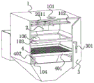
FIG. 1 is a cross-sectional view of the front side view of the present invention;
fig. 2 is a structural diagram of the left side view of the utility model after the door is opened;
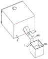
FIG. 3 is a right side view of the present invention;
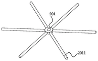
fig. 4 is a connecting structure diagram of the rotating rod and the fixing sleeve of the present invention.
In the drawings, the components represented by the respective reference numerals are listed below:
1. a dust removal box; 101. a feed inlet; 102. mounting a plate; 103. a guide plate; 104. a fixing plate; 105. a discharge port; 106. screening a screen; 2. a drive motor; 201. fixing a sleeve; 2011. rotating the rod; 3. a box door; 301. pressing the lock; 4. filtering and screening; 401. folding edges; 402. a spring; 5. a vibrator; 6. a blower; 601. a connecting pipe; 7. a water tank; 701. liquid water.
Detailed Description
The technical solution in the embodiments of the present invention will be clearly and completely described below with reference to the accompanying drawings in the embodiments of the present invention.
Referring to fig. 1-4, the utility model relates to a crude rice processing dust extraction apparatus, including dust removal case 1, crude rice accomplishes the dust removal in dust removal case 1, the left side of dust removal case 1 is provided with chamber door 3, after opening chamber door 3, can maintain the structure in dust removal case 1, when iron impurity remains on filter sieve 4, open chamber door 3 and can take out iron impurity, the driving motor 2 that sets up in the intermediate position department of dust removal case 1 inside works and makes fixed cover 201 rotate, a plurality of dwang 2011 that set up outside the power output shaft of driving motor 2 rotate and can exert the effort to crude rice, strike crude rice, make the dust on crude rice surface break away from crude rice, the inside that corresponds dust removal case 1 below driving motor 2 is provided with filter sieve 4, filter sieve 4 uses magnetic sieve 4, filter sieve 4 not only can filter the great impurity that mixes in crude rice, still can adsorb iron impurity, avoid iron impurity doping in the gross rice, the fixed bobbing machine 5 during operation of lower wall of filter sieve 4 makes filter sieve 4 vibrate, take place accumulational condition when avoiding the gross rice to pass filter sieve 4, the fixed air-blower 6 work of the right wall of dust removal case 1 can be carried the inside of dust removal case 1 to connecting pipe 601, the downside in air-blower 6 right side is provided with water tank 7, the liquid water 701 of the inside setting of water tank 7 can be detained the dust, make dust and liquid water 701 mix, air-blower 6, driving motor 2 and bobbing machine 5's input all through conductor wire and external power source electric connection, driving motor 2 in this device, bobbing machine 5 and air-blower 6 are prior art, do not injecing its model here.
As shown in fig. 1, 2, and 4, the door 3 is rotatably connected to the dust box 1 through a hinge, the door 3 and the dust box 1 can be in a movable or immovable state by a pressing lock 301 fixed on a side of a left wall of the door 3 far from the hinge, when the door 3 needs to be opened or closed, the door 3 can be opened or closed by operating the pressing lock 301, the top and the bottom of the dust box 1 are respectively and correspondingly provided with a feed inlet 101 and a discharge outlet 105, and the feed inlet 101 is located on the left side of an upper wall of the dust box 1, when crude rice is fed into the dust box 1, external conveying equipment can be used to enable the crude rice to uniformly pass through the feed inlet 101 to enter the inside of the dust box 1, and the crude rice after dust removal can be separated from the dust box 1 from the discharge outlet 105 at the bottom of the dust box 1.
The inner wall that driving motor 2's top corresponds dust removal case 1 is fixed with mounting panel 102, and the cross section of mounting panel 102 sets up for T shape, and mounting panel 102 level sets up, and driving motor 2 fixes the lower surface at mounting panel 102, is fixed with fixed cover 201 on driving motor 2's the power output shaft, and fixed cover 201 accessible bolt is fixed with driving motor 2's power output shaft, and dwang 2011 evenly fixes on the periphery wall of fixed cover 201, and the length of a plurality of dwangs 2011 is the same.
A guide plate 103 is fixed above the filter screen 4 corresponding to the inner wall of the dust removing box 1, the inner side of the guide plate 103 is arranged in a hollow way, and the horizontal plane of the outer end of the guide plate 103 is higher than the horizontal plane of the inner end of the guide plate 103, the inner side of the guide plate 103 is partially overlapped with the filter sieve 4, the coarse rice entering the dust removing box 1 randomly moves in the dust removing box 1 under the state that the rotating rod 2011 rotates, and the guide plate 103 is arranged to make the raw rice finally fall on the upper wall of the filter sieve 4, and the hem 401 arranged at the edge of the upper wall of the filter sieve 4 can prevent the vibrating machine 5 from being damaged when the vibrating machine 5 works, the raw rice drops downwards from the gap between the filter screen 4 and the dust removing box 1 along the horizontal direction of the filter screen 4 without being filtered, that is, the hems 401 limit the moving range of the raw rice to the filter sieve 4, and fall to the bottom of the dust removing box 1 after being filtered by the filter sieve 4 to be separated from the inside of the dust removing box 1.
All be fixed with spring 402 in four corner positions of filter sieve 4 lower wall, bobbing machine 5 during operation, under the effect of spring 402, make filter sieve 4 be in the shock condition for dust removal case 1, the fixed plate 104 that the lower extreme of spring 402 corresponds the equal fixed of inner wall of dust removal case 1 can provide fixed platform for spring 402, and the lower extreme of spring 402 is fixed at the upper surface of fixed plate 104, the inner wall that the air inlet end position department of air-blower 6 corresponds dust removal case 1 is fixed with screen cloth 106, the setting of screen cloth 106 can avoid the inside that the gross rice got into air-blower 6 and causes the reduction of air-blower 6's life.
As shown in fig. 1 and 3, a connection pipe 601 is fixed at an air outlet end of the blower 6, the other end of the connection pipe 601 is fixed on a side wall of a lower side of the water tank 7, the air outlet end of the blower 6 is communicated with the inside of the connection pipe 601, the air inlet end of the blower 6 is communicated with the inside of the dust removing tank 1, the inside of the connection pipe 601 is communicated with the inside of the water tank 7, when the blower 6 works, air carrying dust in the inside of the dust removing tank 1 sequentially passes through the screen 106, the blower 6 and the connection pipe 601 to contact with the liquid water 701, wherein the air can pass through the liquid water 701 to be separated from the liquid water 701, and the dust is blocked in the liquid water 701.
One specific application of this embodiment is: when the crude rice is dedusted, firstly, the power supplies of the driving motor 2, the vibrating machine 5 and the air blower 6 are switched on, the crude rice penetrates through the feed port 101 at a constant speed and enters the interior of the dedusting box 1, when the driving motor 2 works, the power output shaft of the driving motor 2 rotates to drive the fixing sleeve 201 to rotate, then the rotating rod 2011 rotates to apply acting force on the crude rice, so that the dust on the surface of the crude rice is separated from the crude rice, the crude rice after dedusting can fall onto the filter sieve 4, under the action of the vibrating machine 5, the crude rice penetrates through the filter sieve 4 and is discharged to the exterior of the dedusting box 1 from the discharge port 105, when the crude rice penetrates through the filter sieve 4, the filter sieve 4 has magnetism, so that the iron impurities in the crude rice can be adsorbed, meanwhile, the air blower 6 works to convey the dust in the interior of the dedusting box 1 to the interior of the connecting pipe 601, under the continuous action of the air blower 6, the air carrying the dust passes through the liquid water 701 and is separated from the interior of the water tank 7, while the dust is mixed with the liquid water 701.
The above is only the preferred embodiment of the present invention, and the present invention is not limited thereto, any technical solutions recorded in the foregoing embodiments are modified, and some technical features thereof are replaced with equivalent ones, and any modification, equivalent replacement, and improvement made thereby all belong to the protection scope of the present invention.
Claims (6)
1. The utility model provides a rice processing dust extraction, includes dust removal case (1), its characterized in that: the left side of dust removal case (1) is provided with chamber door (3), the inboard intermediate position department of dust removal case (1) is provided with driving motor (2), the power output shaft's of driving motor (2) outside is provided with a plurality of dwang (2011), the inside that the below of driving motor (2) corresponds dust removal case (1) is provided with filter sieve (4), the lower wall of filter sieve (4) is fixed with bobbing machine (5), the right wall of dust removal case (1) is fixed with air-blower (6), the downside in air-blower (6) right side is provided with water tank (7), the inside of water tank (7) is provided with liquid water (701).
2. A wool rice processing dust extraction according to claim 1, characterized in that chamber door (3) is connected with dust removal case (1) through the hinge rotation, the one side of chamber door (3) left wall far away from the hinge is fixed with presses down lock (301), feed inlet (101) and discharge gate (105) have been seted up respectively to the top and the bottom of dust removal case (1) correspondence, and feed inlet (101) are located the left side of dust removal case (1) upper wall.
3. A wool rice processing dust extraction of claim 1, characterized in that, the inner wall that corresponds dust removal case (1) in the top of driving motor (2) is fixed with mounting panel (102), and the cross section of mounting panel (102) sets up for the T, driving motor (2) are fixed at the lower surface of mounting panel (102), be fixed with fixed cover (201) on the power output shaft of driving motor (2), and dwang (2011) evenly fixes on the periphery wall of fixed cover (201).
4. A wool rice processing dust extraction according to claim 1, characterized in that a guide plate (103) is fixed above the filter screen (4) corresponding to the inner wall of the dust removal box (1), the inner side of the guide plate (103) is hollow, the horizontal plane of the outer end of the guide plate (103) is higher than the horizontal plane of the inner end of the guide plate (103), and a folded edge (401) is arranged along the edge of the upper wall of the filter screen (4).
5. A wool rice processing dust extraction according to claim 1, characterized in that springs (402) are fixed at four corners of the lower wall of the filter sieve (4), a fixing plate (104) is fixed at the lower end of each spring (402) corresponding to the inner wall of the dust removal box (1), the lower end of each spring (402) is fixed on the upper surface of the fixing plate (104), and a screen (106) is fixed at the position of the air inlet end of the air blower (6) corresponding to the inner wall of the dust removal box (1).
6. A rice-processing dust-collecting apparatus according to claim 1, characterized in that the air-out end of said blower (6) is fixed with a connecting pipe (601), and the other end of the connecting pipe (601) is fixed on the side wall of the lower side of the water tank (7), the inside of said connecting pipe (601) is communicated with the inside of the water tank (7).
Priority Applications (1)
| Application Number | Priority Date | Filing Date | Title |
|---|---|---|---|
| CN202121218199.7U CN214681891U (en) | 2021-06-02 | 2021-06-02 | Dust extraction is processed to coarse rice |
Applications Claiming Priority (1)
| Application Number | Priority Date | Filing Date | Title |
|---|---|---|---|
| CN202121218199.7U CN214681891U (en) | 2021-06-02 | 2021-06-02 | Dust extraction is processed to coarse rice |
Publications (1)
| Publication Number | Publication Date |
|---|---|
| CN214681891U true CN214681891U (en) | 2021-11-12 |
Family
ID=78554804
Family Applications (1)
| Application Number | Title | Priority Date | Filing Date |
|---|---|---|---|
| CN202121218199.7U Active CN214681891U (en) | 2021-06-02 | 2021-06-02 | Dust extraction is processed to coarse rice |
Country Status (1)
| Country | Link |
|---|---|
| CN (1) | CN214681891U (en) |
Cited By (2)
| Publication number | Priority date | Publication date | Assignee | Title |
|---|---|---|---|---|
| CN114345438A (en) * | 2022-01-17 | 2022-04-15 | 江苏省农业科学院泰州农科所 | Buckwheat cleaning device and using method thereof |
| CN117483343A (en) * | 2024-01-03 | 2024-02-02 | 河北巨英除尘设备制造安装有限公司 | Broken anti-blocking sack cleaner of steel scrap |
-
2021
- 2021-06-02 CN CN202121218199.7U patent/CN214681891U/en active Active
Cited By (4)
| Publication number | Priority date | Publication date | Assignee | Title |
|---|---|---|---|---|
| CN114345438A (en) * | 2022-01-17 | 2022-04-15 | 江苏省农业科学院泰州农科所 | Buckwheat cleaning device and using method thereof |
| CN114345438B (en) * | 2022-01-17 | 2022-12-13 | 江苏省农业科学院泰州农科所 | Buckwheat cleaning device and using method thereof |
| CN117483343A (en) * | 2024-01-03 | 2024-02-02 | 河北巨英除尘设备制造安装有限公司 | Broken anti-blocking sack cleaner of steel scrap |
| CN117483343B (en) * | 2024-01-03 | 2024-04-16 | 河北巨英除尘设备制造安装有限公司 | Broken anti-blocking sack cleaner of steel scrap |
Similar Documents
| Publication | Publication Date | Title |
|---|---|---|
| CN214681891U (en) | Dust extraction is processed to coarse rice | |
| CN107752104A (en) | Feed manufacturing sieves knot screen | |
| CN110653155A (en) | Grit filter equipment is used in rice production with dust removal function | |
| CN107225020A (en) | A kind of mining machinery breaker | |
| CN115414992B (en) | Recycled concrete preparation raw materials reducing mechanism | |
| CN207385946U (en) | A kind of rice dust removal device | |
| CN206631658U (en) | A kind of flour processing flour mill | |
| CN111229597B (en) | Environment-friendly vibrating screen for grain screening | |
| CN208449908U (en) | A kind of rice Winnowing impurity-removing device | |
| CN213825164U (en) | Screening device for intelligent mineral processing | |
| CN206731545U (en) | A kind of tea screening device | |
| CN205586696U (en) | High -efficient stifled dust collector that strains that prevents who makes fertilizer | |
| CN212493885U (en) | Coal resource green development media sieve equipment | |
| CN210187388U (en) | High-efficient marble leftover bits reducing mechanism | |
| CN210546364U (en) | Soybean edulcoration separation sieve device | |
| CN210190251U (en) | Plastics unloading device that becomes more meticulous | |
| CN107457354B (en) | Molding sand recyclable device | |
| CN219850811U (en) | Screening device for rice processing | |
| CN208177614U (en) | A kind of permanent-magnet iron removing device | |
| CN206425478U (en) | Casting sand reclaims knot screen | |
| CN214717395U (en) | Sand and stone separating crusher | |
| CN217569023U (en) | Material crushing machine for cosmetics | |
| CN209953037U (en) | Semi-closed powder screening machine | |
| CN217595179U (en) | Seed sieving mechanism for farming | |
| CN215964724U (en) | Dustproof effectual screening sand device that construction used |
Legal Events
| Date | Code | Title | Description |
|---|---|---|---|
| GR01 | Patent grant | ||
| GR01 | Patent grant |