CN214669879U - VR glasses with synchronous stadia adjustment mechanism - Google Patents
VR glasses with synchronous stadia adjustment mechanism Download PDFInfo
- Publication number
- CN214669879U CN214669879U CN202121244618.4U CN202121244618U CN214669879U CN 214669879 U CN214669879 U CN 214669879U CN 202121244618 U CN202121244618 U CN 202121244618U CN 214669879 U CN214669879 U CN 214669879U
- Authority
- CN
- China
- Prior art keywords
- fixing
- center
- fixed
- box
- fixedly connected
- Prior art date
- Legal status (The legal status is an assumption and is not a legal conclusion. Google has not performed a legal analysis and makes no representation as to the accuracy of the status listed.)
- Active
Links
Images


Abstract
The utility model discloses a VR glasses with synchronous visual range adjusting mechanism, which comprises a first fixing band, a locking component, a head band, a second fixing band, an eye mask box, a fixing box, an outer cover, a limiting hole, a clamping component, a locking hole, a pressing block, a fixing groove, a switch, a first fixing rod, a second fixing rod, a nasal bracket, a lens, an adjusting mechanism, a fixing block, a jack and a fixing pin, wherein the utility model realizes synchronous centering or separated movement of the lens by driving the rotation of a bidirectional screw rod by a servo motor in the adjusting mechanism, is favorable for realizing synchronous adjustment of visual range, meets the use requirements of people with different interpupillary distances, is favorable for improving the stability of fixing the mobile phone by pressing the clamping block in the clamping component on the clamping of the mobile phone and the pressing block on the outer cover on the mobile phone, realizes the locking and loosening of the locking block and the locking hole by stirring a deflector rod, the degree of tightness of wearing is adjusted according to the head circumference of the wearer, and the wearing comfort degree is improved.
Description
Technical Field
The utility model relates to a VR glasses technical field specifically is a VR glasses with synchronous stadia adjustment mechanism.
Background
VR glasses are VR head-mounted display, virtual reality head-mounted display device. Since this concept was not seen clearly in the early days, calls for VR glasses, VR eyecups, VR helmets, etc. were made according to appearance.
VR glasses on the market today are mainly divided into three categories: external helmet of VR, VR all-in-one and VR box glasses, the first two kinds do not need the cell-phone, and most of low-cost VR glasses on the market are the third kind, and although VR glasses function on the market is comparatively perfect, still have certain weak point, and the concrete problem has following several:
(1) most of the stadia of current VR glasses are not adjustable, and the standard stadia of adoption is difficult to satisfy the user's of different interpupillary distances demand, and the VR glasses that the stadia can be adjusted to a small number needs two eyes to adjust respectively, wastes time and energy.
(2) Current VR glasses adopt the elastic cord to wear as fixed the completion basically, and the regulation of elastic cord is limited, and the person of wearing can appear wearing the condition loose or tension in the use, greatly reduced the comfort level and the stability of wearing.
(3) When the existing VR glasses are used, a user can swing and walk back and forth, the sizes of mobile phones are different, the situation of picture shaking can be caused due to unstable fixation of the mobile phones, and the stability of pictures is reduced.
Disclosure of Invention
An object of the utility model is to provide a VR glasses with synchronous stadia adjustment mechanism to propose the unable synchronous adjustment of stadia, wear the problem of the picture shake that the unstability leads to of uncomfortable and cell-phone fixation in solving above-mentioned background art.
In order to achieve the above object, the utility model provides a following technical scheme: a VR (virtual reality) glasses with a synchronous visual distance adjusting mechanism comprises a first fixing belt, a locking assembly, a head belt, a second fixing belt, an eye shield box, a fixing box, an outer cover, a limiting hole, a clamping assembly, a locking hole, a pressing block, a buckle, a fixing groove, a clamping hole, a switch, a first stop block, a first fixing rod, a second fixing rod, a nasal bracket, a lens, an adjusting mechanism, a fixing block, a jack and a fixing pin, wherein the bottom of one side of the fixing box is hinged with the bottom of the outer cover, the center of one side of the fixing box is provided with the fixing groove, and the centers of four side walls in the fixing groove are respectively provided with the clamping assembly;
the clamping assembly consists of a clamping block, a spiral spring, a fixed plate, a guide rod and a second retaining block, wherein the guide rod is movably penetrated through the two ends of the center of the side wall on one side of the fixed groove respectively, the clamping block is fixedly arranged at one end of the guide rod, the spiral spring is connected to the outer periphery of one end of the guide rod in a surrounding manner, one end of the spiral spring is fixedly connected with the periphery of the two ends of the center on one side of the clamping block, the clamping block is positioned in the fixed groove, the other side of the clamping block is respectively attached to the four sides of the mobile phone, one end of the center of the guide rod is movably penetrated through the two ends of the center on one side of the fixed plate respectively, the periphery of the two ends of the center on one side of the fixed plate is attached to the other end of the spiral spring, the two ends of the center on the opposite side of the fixed plate in the clamping assembly at the top and the bottom of the fixed groove are respectively and fixedly connected with one end of the second fixed rod, and the other end of the second fixed rod is respectively fixedly connected with the top surface and the two sides of the center of the bottom surface in the fixed box, the two ends of the center of one side, opposite to the fixed plate, of the clamping assemblies on the two sides of the fixed groove are respectively and fixedly connected with one end of a first fixed rod, the other end of the first fixed rod is respectively and fixedly connected with the top and the bottom of the centers on the two sides of the interior of the fixed box, the two adjacent sides of the fixed box are respectively and fixedly connected with a first fixed belt and a second fixed belt, and the end, opposite to the fixed box, of the first fixed belt is fixedly connected with a locking assembly;
the locking assembly comprises a rotating shaft, a torsion spring, a rotating rod, a fixed head, a locking block and a shifting lever, wherein the first fixing belt is positioned at the opposite end of the fixed box and is fixedly connected with the corner of the side edge of the fixed head, the central end of the side of the fixed head is provided with an inserting hole, the central corner of the inner bottom surface of the fixed head is provided with the rotating shaft, the rotating shaft is rotatably connected with the central corner of the inner bottom surface of the fixed head, one side of the periphery of the rotating shaft is fixedly connected with one end of the rotating rod, one end of the center of one side of the rotating rod is jointed with one side of the torsion spring, the torsion spring is sleeved on the fixed pin, the fixed pin is fixedly arranged at one side of the center of the inner bottom surface of the fixed head, the other side of the torsion spring is jointed with the side wall of the inner side of the fixed head, the locking block is arranged at the corner of the other side of the rotating rod, and is clamped inside the locking hole, and the locking hole is uniformly arranged at one side of the second fixing belt, an eyeshade box is arranged in the center of the other side of the fixed box, and an adjusting mechanism is arranged in the eyeshade box;
adjustment mechanism includes connecting block, two-way lead screw, base, servo motor, first straight-teeth gear and second straight-teeth gear, the inside top surface one corner of eye-shade case and base top fixed connection, and base bottom center installs servo motor, the servo motor output cup joints and is fixed with first straight-teeth gear, and the outer circumference of first straight-teeth gear and the outer circumference meshing of second straight-teeth gear, second straight-teeth gear fixed mounting is close to terminal surface position at two-way lead screw one end, two-way lead screw center both ends are connected with the connecting block through the ball nut cooperation respectively, and the connecting block bottom respectively with lens top fixed connection, two-way lead screw both ends rotate with fixed block one side center in opposite directions respectively and are connected, and the fixed block other end respectively with upper portion fixed connection in the inside both sides of eye-shade case.
Preferably, the other end of the guide rod is fixedly connected with the center of one side of the second stop block.
Preferably, the four corners of the bottom of the fixing groove are respectively provided with a first stop block, and one side of the first stop block is respectively attached to the four corners of one side of the mobile phone.
Preferably, one end of the top of the rotating rod is fixedly connected with the bottom end of the shifting rod, the top end of the shifting rod movably penetrates through a limiting hole, and the limiting hole is formed in one side of the top of the fixing head.
Preferably, one side of the top of the fixed box is fixedly connected with one end of the head band, and the other end of the head band and the fixed head are fixedly connected with the top of the side, adjacent to the insertion hole, of the fixed head.
Preferably, the first fixing band, the second fixing band and the head band are two layers, the outer layer is a rubber layer, and the inner layer is a sponge layer.
Preferably, the center of the bottom of the eyeshade box is provided with a nasal bracket, and a sponge cushion pad is arranged on the side, opposite to the fixing box, of the eyeshade box.
Preferably, a switch is installed at one corner position of the top of the fixed box.
Preferably, compact heap is installed respectively at enclosing cover inboard center both ends, enclosing cover inboard center top and buckle one end fixed connection, and the buckle other end joint is inside the joint hole, the joint hole is seted up at fixed box one side center top.
Compared with the prior art, the beneficial effects of the utility model are that:
(1) the utility model discloses a servo motor drives the rotation of two-way lead screw among the adjustment mechanism to realized the synchronous centering of lens or the motion of leaving mutually, be favorable to realizing the synchronous adjustment of stadia, satisfied the user demand of the people of different interpupillary distances, promoted the practicality of equipment.
(2) The utility model discloses a pressing block of the tight piece of clamp among the clamping component to the centre gripping of cell-phone and the compact heap on the enclosing cover to compressing tightly of cell-phone is favorable to promoting the fixed stability of cell-phone, has avoided the problem of picture shake to appear.
(3) The utility model discloses a stir the driving lever and realize the locking of latch segment and locking hole and loosen, be favorable to adjusting the elasticity degree of wearing according to wearer's head circumference, promoted the comfortable degree of wearing, be favorable to lifting means's practicality.
Drawings
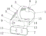
FIG. 1 is a perspective view of the overall structure of the present invention;
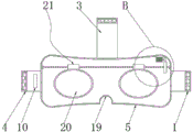
fig. 2 is a schematic view of the overall structure of the present invention with the outer cover opened;
fig. 3 and 4 are front and sectional views of the overall structure of the present invention;
fig. 5 is an enlarged schematic view of the area a in fig. 3 according to the present invention;
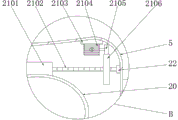
fig. 6 is an enlarged schematic view of the area B in fig. 4 according to the present invention;
fig. 7 is a top sectional view of the overall structure of the present invention;
fig. 8 is an enlarged schematic view of the region C in fig. 7 according to the present invention;
in the figure: 1. a first securing strap; 2. a locking assembly; 3. a headband; 4. a second securing strap; 5. an eyeshade box; 6. a fixing box; 7. an outer cover; 8. a limiting hole; 9. a clamping assembly; 10. a locking hole; 11. a compression block; 12. buckling; 13. fixing grooves; 14. a clamping hole; 15. a switch; 16. a first stopper; 17. a first fixing lever; 18. a second fixing bar; 19. a nasal bracket; 20. a lens; 21. an adjustment mechanism; 22. a fixed block; 23. a jack; 24. a fixing pin; 901. a clamping block; 902. a coil spring; 903. a fixing plate; 904. a guide bar; 905. a second stopper; 201. a rotating shaft; 202. a torsion spring; 203. rotating the rod; 204. a fixed head; 205. a locking block; 206. a deflector rod; 2101. connecting blocks; 2102. a bidirectional screw rod; 2103. a base; 2104. a servo motor; 2105. a first straight gear; 2106. a second spur gear.
Detailed Description
The technical solutions in the embodiments of the present invention will be described clearly and completely with reference to the accompanying drawings in the embodiments of the present invention, and it is obvious that the described embodiments are only some embodiments of the present invention, not all embodiments. Based on the embodiments in the present invention, all other embodiments obtained by a person skilled in the art without creative work belong to the protection scope of the present invention.
Referring to fig. 1-8, the present invention provides an embodiment: a VR (virtual reality) glasses with a synchronous visual distance adjusting mechanism comprises a first fixing band 1, a locking component 2, a head band 3, a second fixing band 4, an eye shield box 5, a fixing box 6, an outer cover 7, a limiting hole 8, a clamping component 9, a locking hole 10, a pressing block 11, a buckle 12, a fixing groove 13, a clamping hole 14, a switch 15, a first stop block 16, a first fixing rod 17, a second fixing rod 18, a nose support groove 19, a lens 20, an adjusting mechanism 21, a fixing block 22, a jack 23 and a fixing pin 24, wherein the bottom of one side of the fixing box 6 is hinged with the bottom of the outer cover 7, the switch 15 is arranged at one corner of the top of the fixing box 6, the pressing blocks 11 are respectively arranged at two ends of the center of the inner side of the outer cover 7, the top of the center of the inner side of the outer cover 7 is fixedly connected with one end of the buckle 12, the other end of the buckle 12 is clamped in the clamping hole 14, the clamping hole 14 is arranged at the top of the center of one side of the fixing box 6, and is beneficial for pressing a mobile phone through the pressing blocks 11, a fixing groove 13 is formed in the center of one side of the fixing box 6, first stop blocks 16 are respectively mounted at four corners of the bottom of the fixing groove 13, one side of each first stop block 16 is respectively attached to four corners of one side of the mobile phone, fixing of the mobile phone is facilitated, and clamping assemblies 9 are respectively mounted at the centers of four side walls inside the fixing groove 13;
the clamping assembly 9 is composed of a clamping block 901, a spiral spring 902, a fixing plate 903, a guide rod 904 and a second stop 905, two ends of the center of the side wall of one side of the fixing groove 13 are respectively and movably penetrated with the guide rod 904, the other end of the guide rod 904 is fixedly connected with the center of one side of the second stop 905, the overtravel of the guide rod 904 is effectively avoided by the additional installation of the second stop 905, one end of the guide rod 904 is fixedly provided with the clamping block 901, the periphery of one end of the guide rod 904 is connected with the spiral spring 902 in a winding manner, one end of the spiral spring 902 is fixedly connected with the periphery of two ends of the center of one side of the clamping block 901, the clamping block 901 is positioned in the fixing groove 13, the other side of the clamping block 901 is respectively attached to four sides of the mobile phone, one end of the center of the guide rod 904 is respectively and movably penetrated through two ends of the center of one side of the fixing plate 903, two ends of one side of the fixing plate 903 is attached to the other end of the spiral spring 902, the center of the opposite side of the fixing plate 903 in the fixing groove in the clamping assembly 9 at the top and the bottom of the fixing plate 13 is respectively and fixedly connected with one end of the second fixing rod 18, the other end of the second fixing rod 18 is fixedly connected with the top surface and two sides of the center of the bottom surface in the fixing box 6 respectively, two ends of the center of the opposite side of the fixing plate 903 in the clamping assemblies 9 on two sides of the fixing groove 13 are fixedly connected with one end of the first fixing rod 17 respectively, the other end of the first fixing rod 17 is fixedly connected with the top and the bottom of the center of two sides in the fixing box 6 respectively, the two adjacent sides of the fixing box 6 on the fixing groove 13 are fixedly connected with a first fixing belt 1 and a second fixing belt 4 respectively, and the end of the first fixing belt 1 on the opposite side of the fixing box 6 is fixedly connected with a locking assembly 2;
the locking component 2 comprises a rotating shaft 201, a torsion spring 202, a rotating rod 203, a fixed head 204, a locking block 205 and a shifting rod 206, wherein the first fixing band 1 is positioned at the opposite end of the fixed box 6 and fixedly connected with the corner of one side of the fixed head 204, one end of the center of one side of the fixed head 204 is provided with a jack 23, one corner of the center of the bottom surface inside the fixed head 204 is provided with the rotating shaft 201, the rotating shaft 201 is rotatably connected with one corner of the center of the bottom surface inside the fixed head 204, one side of the periphery of the rotating shaft 201 is fixedly connected with one end of the rotating rod 203, one end of the top of the rotating rod 203 is fixedly connected with the bottom end of the shifting rod 206, the top end of the shifting rod 206 movably penetrates through a limiting hole 8, the limiting hole 8 is arranged at one side of the top of the fixed head 204, the rotating rod 203 is driven to rotate along the rotating shaft 201 by the shifting rod 206, one end of the center of one side of the rotating rod 203 is attached to one side of the torsion spring 202, the torsion spring 202 is sleeved on the fixing pin 24, the fixing pin 24 is fixedly arranged at one side of the center of the bottom surface inside the fixed head 204, the other side of the torsion spring 202 is attached to the inner side wall of the fixing head 204, one side of the top of the fixing box 6 is fixedly connected with one end of the head band 3, the other end of the head band 3 is fixedly connected with the top of the fixing head 204 at the side adjacent to the jack 23, and therefore the fixing installation of the head band 3 is facilitated, the first fixing band 1, the second fixing band 4 and the head band 3 are two layers, the outer layer is a rubber layer, the inner layer is a sponge layer, and the wearing comfort is facilitated to be improved, the locking block 205 is installed at the corner of the other side of the rotating rod 203, the locking block 205 is clamped inside the locking hole 10, the locking hole 10 is uniformly formed in one side of the second fixing band 4, the center of the other side of the fixing box 6 is provided with the eyeshade box 5, and the adjusting mechanism 21 is installed inside the eyeshade box 5;
the adjusting mechanism 21 comprises a connecting block 2101, a two-way screw mandrel 2102, a base 2103, a servo motor 2104, a first straight gear 2105 and a second straight gear 2106, one corner of the inner top surface of the eyeshade box 5 is fixedly connected with the top of the base 2103, the servo motor 2104 is installed at the center of the bottom of the base 2103, the first straight gear 2105 is fixedly sleeved and fixed at the output end of the servo motor 2104, the outer circumference of the first straight gear 2105 is meshed with the outer circumference of the second straight gear 2106, the second straight gear 2106 is fixedly installed at the position, close to the end face, of one end of the two-way screw mandrel 2102, the two ends of the center of the two-way screw mandrel 2102 are respectively connected with the connecting block 2101 in a matching way through ball nuts, the bottom of the connecting block 2101 is respectively fixedly connected with the top of the lens 20, the two ends of the two-way screw mandrel 2102 are respectively connected with the center of one side of the fixing block 22 in a rotating way, the other end of the fixing block 22 is respectively fixedly connected with the middle upper parts of the two sides of the eyeshade box 5, the center of the bottom of the eyeshade box 5 is provided with a nose bracket 19, the sponge blotter is installed to the opposite side that eye-shade case 5 is located fixed box 6, is favorable to promoting the travelling comfort of wearing.
The working principle is as follows: when the utility model is used, firstly, the outer cover 7 is opened, then the clamping block 901 is pressed towards the direction of the fixing plate 903, thereby the guide rod 904 is driven to move towards the direction of the fixing plate 903, then the spiral spring 902 is compressed, at the moment, the mobile phone is placed into the fixing groove 13, the clamping block 901 is loosened, under the action of the restoring force of the spiral spring 902, the clamping block 901 is driven to move towards the opposite direction of the fixing plate 903, thereby the mobile phone is clamped, then the outer cover 7 is covered, the pressing block 11 on the outer cover 7 presses the mobile phone, the stable installation of the mobile phone is facilitated, the unstable picture condition caused by the shaking of the mobile phone is avoided, the watching comfort level is improved, then the equipment is worn on the head, then the deflector rod 206 is stirred along the direction of the limiting hole 8, the deflector rod 206 is immediately driven to rotate along the rotating shaft 201, then the rotating rod 203 is driven to rotate along the rotating shaft 201, then the locking block 205 is driven to rotate along the rotating shaft 201, then the torsion spring 202 is compressed, then the second fixing belt 4 is inserted into the jack 23 in the fixing head 204, after the proper tightness is adjusted according to the head circumference, the deflector rod 206 is loosened, the rotating rod 203 is driven to rotate along the rotating shaft 201 in the reverse direction under the action of the restoring force of the torsion spring 202, then the locking block 205 is driven to rotate along the rotating shaft 201 in the reverse direction, so that the locking block 205 and the locking hole 10 are clamped and locked, the tightness adjustment according to the head circumference of a user is facilitated, the situations of over-looseness and over-tightness are avoided, the wearing comfort is facilitated to be improved, after the wearing is completed, the visual range adjustment can be performed according to the pupil range, the servo motor 2104 is opened, the output end of the servo motor 2104 starts to rotate, then the first straight gear 2105 is driven to rotate, then the second straight gear 2106 is driven to rotate, the gear ratio of the first straight gear 2105 to the second straight gear 2106 is 1: 10, and then the bidirectional screw 2102 is driven to rotate, then drive the connecting block 2101 centering motion of two-way lead screw 2102 both sides, drive lens 20 centering motion afterwards, reversal servo motor 2104 to realized the motion of separating from each other of lens 20, realized the synchronous adjustment of stadia, be favorable to carrying out stadia adjustment according to user's interpupillary distance, promoted the practicality of equipment.
It is obvious to a person skilled in the art that the invention is not restricted to details of the above-described exemplary embodiments, but that it can be implemented in other specific forms without departing from the spirit or essential characteristics of the invention. The present embodiments are therefore to be considered in all respects as illustrative and not restrictive, the scope of the invention being indicated by the appended claims rather than by the foregoing description, and all changes which come within the meaning and range of equivalency of the claims are therefore intended to be embraced therein. Any reference sign in a claim should not be construed as limiting the claim concerned.
Claims (9)
1. The utility model provides a VR glasses with synchronous stadia adjustment mechanism, including first fixed band (1), locking Assembly (2), bandeau (3), second fixed band (4), eye-shade case (5), fixed box (6), enclosing cover (7), spacing hole (8), clamping assembly (9), locking hole (10), compact heap (11), buckle (12), fixed slot (13), joint hole (14), switch (15), first dog (16), first dead lever (17), second dead lever (18), nose support groove (19), lens (20), adjustment mechanism (21), fixed block (22), jack (23) and fixed pin (24), its characterized in that: the bottom of one side of the fixed box (6) is hinged with the bottom of the outer cover (7), a fixed groove (13) is formed in the center of one side of the fixed box (6), and clamping assemblies (9) are mounted at the centers of four side walls in the fixed groove (13) respectively;
clamping unit (9) is by pressing from both sides tight piece (901), coil spring (902), fixed plate (903), guide bar (904) and second dog (905) and constitutes, fixed slot (13) one side lateral wall center both ends activity respectively run through have guide bar (904), guide bar (904) one end fixed mounting has and presss from both sides tight piece (901), and guide bar (904) one end is outer to have connect coil spring (902) around having, coil spring (902) one end and the peripheral fixed connection in the tight piece (901) one side center both ends of clamp, and press from both sides tight piece (901) and be located inside fixed slot (13), press from both sides tight piece (901) opposite side center both ends with the cell-phone four sides laminating respectively, fixed plate (903) one side center both ends are run through in the activity respectively to guide bar (904) center one end, fixed plate (903) one side center both ends periphery and coil spring (902) other end laminating, fixed slot (13) top and the fixed plate (903) opposite side center in the clamping unit (9) of bottom center Two ends of the second fixing rod (18) are fixedly connected with one end of the second fixing rod respectively, the other end of the second fixing rod (18) is fixedly connected with two sides of the top surface and the center of the bottom surface in the fixing box (6) respectively, two ends of the center of one side, opposite to the fixing plate (903), of the clamping assemblies (9) on two sides of the fixing groove (13) are fixedly connected with one end of the first fixing rod (17) respectively, the other end of the first fixing rod (17) is fixedly connected with the top and the bottom of the center of two sides in the fixing box (6) respectively, the two adjacent sides of the fixing box (6) on the fixing groove (13) are fixedly connected with the first fixing belt (1) and the second fixing belt (4) respectively, and the end, opposite to the fixing box (6), of the first fixing belt (1) is fixedly connected with the locking assembly (2);
the locking assembly (2) comprises a rotating shaft (201), a torsion spring (202), a rotating rod (203), a fixing head (204), a locking block (205) and a shifting rod (206), wherein a first fixing band (1) is located at one end opposite to a fixing box (6) and fixedly connected with the corner of one side of the fixing head (204), a jack (23) is formed in one end of the center of one side of the fixing head (204), the rotating shaft (201) is installed at one corner of the center of the inner bottom surface of the fixing head (204), the rotating shaft (201) is rotatably connected with one corner of the center of the inner bottom surface of the fixing head (204), one side of the periphery of the rotating shaft (201) is fixedly connected with one end of the rotating rod (203), one end of the center of one side of the rotating rod (203) is attached to one side of the torsion spring (202), the torsion spring (202) is sleeved on the fixing pin (24), and the fixing pin (24) is fixedly installed on one side of the center of the inner bottom surface of the fixing head (204), the other side of the torsion spring (202) is attached to the inner side wall of the fixing head (204), a locking block (205) is installed at the corner of the other side of the rotating rod (203), the locking block (205) is clamped inside a locking hole (10), the locking hole (10) is uniformly formed in one side of the second fixing belt (4), an eyeshade box (5) is installed in the center of the other side of the fixing box (6), and an adjusting mechanism (21) is installed inside the eyeshade box (5);
the adjusting mechanism (21) comprises a connecting block (2101), a two-way screw rod (2102), a base (2103), a servo motor (2104), a first straight gear (2105) and a second straight gear (2106), one corner of the inner top surface of the eye shield box (5) is fixedly connected with the top of the base (2103), the servo motor (2104) is installed at the center of the bottom of the base (2103), the output end of the servo motor (2104) is fixedly connected with the first straight gear (2105) in a sleeved mode, the outer circumference of the first straight gear (2105) is meshed with the outer circumference of the second straight gear (2106), the second straight gear (2106) is fixedly installed at one end of the two-way screw rod (2102) and close to the end face position, the two ends of the center of the two-way screw rod (2102) are respectively connected with the connecting block (2101) in a matched mode through ball nuts, the bottom of the connecting block (2101) is respectively fixedly connected with the top of a lens (20), the two ends of the two-way screw rod (2102) are respectively connected with the fixing block (22) in a center rotation mode in the opposite side, and the other end of the fixing block (22) is respectively fixedly connected with the middle upper parts of the two sides of the inside of the eyeshade box (5).
2. The VR glasses with synchronized range-of-sight adjustment mechanism of claim 1, wherein: the other end of the guide rod (904) is fixedly connected with the center of one side of the second stop block (905).
3. The VR glasses with synchronized range-of-sight adjustment mechanism of claim 1, wherein: first stop blocks (16) are respectively installed at four corners of the bottom of the fixing groove (13), and one side of each first stop block (16) is respectively attached to four corners of one side of the mobile phone.
4. The VR glasses with synchronized range-of-sight adjustment mechanism of claim 1, wherein: dwang (203) top one end and driving lever (206) bottom fixed connection, and driving lever (206) top activity runs through spacing hole (8), spacing hole (8) are seted up in fixed head (204) top one side.
5. The VR glasses with synchronized range-of-sight adjustment mechanism of claim 1, wherein: one side of the top of the fixed box (6) is fixedly connected with one end of the head belt (3), and the other end of the head belt (3) is fixedly connected with the top of the fixed head (204) at the adjacent side of the jack (23).
6. The VR glasses with synchronized range-of-sight adjustment mechanism of claim 1, wherein: the first fixing belt (1), the second fixing belt (4) and the head belt (3) are two layers, the outer layer is a rubber layer, and the inner layer is a sponge layer.
7. The VR glasses with synchronized range-of-sight adjustment mechanism of claim 1, wherein: the center of the bottom of the eyeshade box (5) is provided with a nose support groove (19), and a sponge cushion pad is arranged on one side, opposite to the fixing box (6), of the eyeshade box (5).
8. The VR glasses with synchronized range-of-sight adjustment mechanism of claim 1, wherein: and a switch (15) is arranged at one corner of the top of the fixed box (6).
9. The VR glasses with synchronized range-of-sight adjustment mechanism of claim 1, wherein: compact heap (11) are installed respectively at enclosing cover (7) inboard center both ends, enclosing cover (7) inboard center top and buckle (12) one end fixed connection, and inside buckle (12) other end joint in joint hole (14), joint hole (14) are seted up at fixed box (6) one side center top.
Priority Applications (1)
| Application Number | Priority Date | Filing Date | Title |
|---|---|---|---|
| CN202121244618.4U CN214669879U (en) | 2021-06-04 | 2021-06-04 | VR glasses with synchronous stadia adjustment mechanism |
Applications Claiming Priority (1)
| Application Number | Priority Date | Filing Date | Title |
|---|---|---|---|
| CN202121244618.4U CN214669879U (en) | 2021-06-04 | 2021-06-04 | VR glasses with synchronous stadia adjustment mechanism |
Publications (1)
| Publication Number | Publication Date |
|---|---|
| CN214669879U true CN214669879U (en) | 2021-11-09 |
Family
ID=78486598
Family Applications (1)
| Application Number | Title | Priority Date | Filing Date |
|---|---|---|---|
| CN202121244618.4U Active CN214669879U (en) | 2021-06-04 | 2021-06-04 | VR glasses with synchronous stadia adjustment mechanism |
Country Status (1)
| Country | Link |
|---|---|
| CN (1) | CN214669879U (en) |
-
2021
- 2021-06-04 CN CN202121244618.4U patent/CN214669879U/en active Active
Similar Documents
| Publication | Publication Date | Title |
|---|---|---|
| CN211506036U (en) | Adjustable head wears and head-mounted apparatus | |
| CN214669879U (en) | VR glasses with synchronous stadia adjustment mechanism | |
| CN113238381A (en) | VR glasses with synchronous stadia adjustment mechanism | |
| CN211857056U (en) | Anti-drop's VR equipment in motion process | |
| CN218455825U (en) | Novel VR head-mounted apparatus | |
| CN208477213U (en) | A kind of VR glasses of adjustable comfortable wearing | |
| CN213149377U (en) | Wear-type virtual reality equipment | |
| CN216351559U (en) | AR glasses that applicable different crowds wore | |
| CN215986729U (en) | Novel anti-drop VR glasses | |
| CN214467739U (en) | Wear-type VR equipment anti-falling device | |
| CN214151254U (en) | Anti-drop's VR simulation helmet based on tourism environment | |
| CN212911894U (en) | Anti-drop helmet based on VR training | |
| CN219609352U (en) | Adjustable VR glasses | |
| CN115113406B (en) | VR equipment convenient to dress | |
| CN216571445U (en) | Novel bluetooth headset swimming goggles | |
| CN213149380U (en) | VR glasses with good fixity | |
| CN216526535U (en) | VR glasses | |
| CN117518504B (en) | Head-mounted display device | |
| CN214252755U (en) | VR head-mounted apparatus capable of preventing falling | |
| CN210690944U (en) | Novel intelligence is dressed and is used VR glasses | |
| CN217689624U (en) | VR glasses bandeau | |
| CN217718267U (en) | VR interactive equipment that computer communication was used | |
| CN219501933U (en) | Folding diving glasses | |
| CN210294684U (en) | Adjusting mechanism for virtual reality helmet | |
| US20240028074A1 (en) | Vr glasses headband |
Legal Events
| Date | Code | Title | Description |
|---|---|---|---|
| GR01 | Patent grant | ||
| GR01 | Patent grant |