CN214614269U - Efficient water conservancy construction sediment removal device - Google Patents
Efficient water conservancy construction sediment removal device Download PDFInfo
- Publication number
- CN214614269U CN214614269U CN202120047889.4U CN202120047889U CN214614269U CN 214614269 U CN214614269 U CN 214614269U CN 202120047889 U CN202120047889 U CN 202120047889U CN 214614269 U CN214614269 U CN 214614269U
- Authority
- CN
- China
- Prior art keywords
- water
- box body
- fixedly arranged
- movably inserted
- storage tank
- Prior art date
- Legal status (The legal status is an assumption and is not a legal conclusion. Google has not performed a legal analysis and makes no representation as to the accuracy of the status listed.)
- Active
Links
Images


Landscapes
- Treatment Of Sludge (AREA)
Abstract
The utility model discloses an efficient water conservancy construction dredging device, which comprises a box body, wherein one side of the box body is symmetrically and fixedly provided with a protective box, the upper surface of the protective box is provided with a first door plate in a rotating way, one side of the box body is fixedly provided with a water storage tank, the upper surface of the water storage tank is provided with a second door plate in a rotating way, one side of the box body is fixedly provided with a cutting sleeve, the inner part of the cutting sleeve is movably inserted with a high-pressure water gun body, one end of the high-pressure water gun body is movably inserted with a water delivery pipe, compared with the prior art, the water pump in the water storage tank is opened to convey the water in the water storage tank to the inner part of the high-pressure water gun body through a three-way pipe and the water delivery pipe, then the high-pressure water gun body is manually taken out from the inner part of the cutting sleeve, and the silt on the surface of the inner structure of the dredging device is cleaned, thereby the cleaning of the silt on the surface of the inner structure of the dredging device is completed, and then the subsequent maintenance convenience of the dredging device is effectively improved.
Description
Technical Field
The utility model relates to a water conservancy construction desilting technical field specifically is an efficient water conservancy construction desilting device.
Background
Hydraulic engineering: hydraulic engineering is an engineering built for controlling and allocating surface water and underground water in nature to achieve the purposes of removing harmful substances and benefiting. Also known as water engineering. Water is a valuable resource essential for human production and life, but its naturally occurring state does not completely meet the needs of human beings. Only when hydraulic engineering is built, water flow can be controlled, flood disasters are prevented, and water quantity is adjusted and distributed to meet the requirements of people on water resources in life and production. Hydraulic engineering needs to build various types of hydraulic buildings such as dams, dikes, spillways, water gates, water inlets, channels, transition troughs, rafts, fishways and the like so as to achieve the aims. At present, often use the sediment removal device during hydraulic engineering construction, current sediment removal device leads to taking out the silt pipe and blocks up extremely easily because of the influence of weeds and other debris in the silt when pumping silt, consequently leads to desilting work efficiency low, and after the desilting work, the inconvenient clearance of silt on sediment removal device inner structure surface, for this we provide an efficient water conservancy construction sediment removal device and be used for solving above-mentioned problem.
Disclosure of Invention
An object of the utility model is to provide an efficient water conservancy construction sediment removal device to solve the problem that proposes in the above-mentioned background art.
In order to achieve the above object, the utility model provides a following technical scheme: a high-efficiency water conservancy construction dredging device comprises a box body, wherein protective boxes are symmetrically and fixedly arranged on one side of the box body, a first door plate is arranged on the upper surface of each protective box in a rotating mode, a water storage tank is fixedly arranged on one side of the box body, a second door plate is arranged on the upper surface of the water storage tank in a rotating mode, a clamping sleeve is fixedly arranged on one side of the box body, a high-pressure water gun body is movably inserted into the clamping sleeve, a water delivery pipe is movably inserted into one end of the high-pressure water gun body, a dredging pump body is fixedly arranged on the upper surface of the box body, a sludge discharge pipe is movably inserted into a sewage discharge port of the dredging pump body, a connecting pipe is movably inserted into the sewage discharge port of the dredging pump body, dredging hoses are uniformly and movably inserted into one side of the connecting pipe, the dredging hoses are movably inserted into the box body, bearing seats are uniformly and fixedly arranged on two sides of the box body, and a motor is fixedly arranged in the protective boxes, the water storage tank is characterized in that a rotating rod is fixedly arranged at the driving output end of the motor and is rotatably connected with a bearing seat, a rotating rod is fixedly sleeved on the surface of the rotating rod, stirring blades and blades are symmetrically and fixedly arranged on the surface of the rotating rod respectively, a water pump is fixedly arranged in the water storage tank, a three-way pipe is fixedly arranged at one end of the water pump, and the three-way pipe is movably connected with a water delivery pipe in an inserting mode.
Preferably, the lower surface of the box body is uniformly and fixedly provided with supporting seats.
Preferably, notches are symmetrically formed in two sides of the box body.
Preferably, one side of the protection box is symmetrically and fixedly provided with a first fixing seat, the surface of the first fixing seat is symmetrically threaded and rotatably provided with a first bolt, and the first bolt penetrates through the first fixing seat and is fixedly connected with the box body.
Preferably, a first handle is fixedly arranged on the upper surface of the first door panel, and a second handle is fixedly arranged on the upper surface of the second door panel.
Preferably, one side of the water storage tank is uniformly and fixedly provided with a second fixing seat, the surface of the second fixing seat is symmetrically threaded and rotatably provided with a second bolt, and the second bolt penetrates through the second fixing seat and is fixedly connected with the tank body.
Preferably, a protective cover is fixedly arranged at one end of the silt pumping hose.
Compared with the prior art, the beneficial effects of the utility model are that:
1. the two sets of motors are started, the motors drive the corresponding rotating rods to rotate, the two sets of rotating rods drive the corresponding rotating rods, the stirring blades and the blades rotate, the two sets of stirring blades start to stir the sludge and enable the sludge to be loose, the two sets of stirring blades stir the sludge and simultaneously cut impurities in the sludge, then the sludge pumping pump body is started, the sludge pumping pump body starts to pump the sludge through the connecting pipes and the multiple sets of sludge pumping hoses, the pumped sludge is discharged to the outside through the sludge discharge pipes, so that the sludge is pumped, the blockage of the sludge pumping pipes caused by the impurities in the sludge cleaning device is effectively avoided, and the working efficiency of the sludge cleaning device during sludge pumping is effectively improved;
2. through opening the inside water pump of holding tank, the inside water of water pump will holding tank is carried to the inside of high-pressure squirt body through three-way pipe and raceway, then manually takes out high-pressure squirt body from the inside of cutting ferrule to wash the silt on dredging device inner structure surface, thereby accomplished the washing of the silt on dredging device inner structure surface, and then the effectual convenience that has improved the follow-up maintenance of dredging device.
Drawings
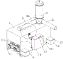
FIG. 1 is a schematic front view of the dredging device of the present invention;
FIG. 2 is an enlarged view of part A of FIG. 1 according to the present invention;
FIG. 3 is an enlarged view of a portion B of FIG. 1 according to the present invention;
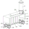
FIG. 4 is a schematic side view of the dredging device of the present invention;
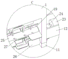
fig. 5 is an enlarged schematic view of the portion C in fig. 4 according to the present invention;
FIG. 6 is a schematic sectional view of the dredging device of the present invention;
FIG. 7 is a schematic sectional view of the water storage tank of the present invention;
fig. 8 is an enlarged schematic view of a portion D of fig. 7 according to the present invention;
in the figure: 1. a box body; 11. a supporting seat; 111. a notch; 12. a protective case; 121. a first fixed seat; 122. a first bolt; 13. a first door panel; 131. a first handle; 14. a water storage tank; 141. a second fixed seat; 142. a second bolt; 15. a second door panel; 151. a second handle; 16. a card sleeve; 17. a high-pressure water gun body; 171. a water delivery pipe; 18. a sludge pumping hose; 181. a protective cover; 19. a bearing seat; 2. a sludge pump body; 21. a sludge discharge pipe; 22. a connecting pipe; 23. a motor; 24. a rotating rod; 25. rotating the stick; 26. a stirring blade; 27. a blade; 28. a water pump; 29. a three-way pipe.
Detailed Description
The technical solutions in the embodiments of the present invention will be described clearly and completely with reference to the accompanying drawings in the embodiments of the present invention, and it is obvious that the described embodiments are only some embodiments of the present invention, not all embodiments. Based on the embodiments in the present invention, all other embodiments obtained by a person skilled in the art without creative work belong to the protection scope of the present invention.
Referring to fig. 1-8, the present invention provides a technical solution: a high-efficiency water conservancy construction dredging device comprises a box body 1, wherein one side of the box body 1 is symmetrically and fixedly provided with a protective box 12, the protective box 12 can isolate external sludge and sewage, the upper surface of the protective box 12 is rotatably provided with a first door plate 13, the opening and closing of the protective box 12 can be conveniently realized by rotating the first door plate 13, one side of the box body 1 is fixedly provided with a water storage tank 14, the inside of the water storage tank 14 can store water, the upper surface of the water storage tank 14 is rotatably provided with a second door plate 15, the opening and closing of the water storage tank 14 can be conveniently realized by rotating the second door plate 15, one side of the box body 1 is fixedly provided with a clamping sleeve 16, the inside of the clamping sleeve 16 is movably inserted with a high-pressure water gun body 17, the inside of the clamping sleeve 16 can conveniently place the high-pressure water gun body 17, the high-pressure water gun body 17 can conveniently realize the sanitary cleaning of the dredging device, one end of the high-pressure water gun body 17 is movably inserted with a water pipe 171, the water pipe 171 can convey water in the water storage tank 14 to the inside of the high-pressure water gun body 17, the upper surface of the box body 1 is fixedly provided with the silt pumping pump body 2, the silt cleaning work of the silt cleaning device can be conveniently realized by opening the silt pumping pump body 2, a sewage discharge outlet of the silt pumping pump body 2 is movably inserted with a silt discharge pipe 21, the silt discharge pipe 21 can discharge silt to the outside, a connecting pipe 22 is movably inserted at the sewage discharge outlet of the silt pumping pump body 2, one side of the connecting pipe 22 is uniformly and movably inserted with a silt pumping hose 18, the connecting pipe 22 and the silt pumping hose 18 can pump silt, the silt pumping hose 18 and the box body 1 are movably inserted, the two sides of the box body 1 are uniformly and fixedly provided with bearing seats 19, the inside of the protective box 12 is fixedly provided with a motor 23, the driving output end of the motor 23 is fixedly provided with a rotating rod 24, the motor 23 can drive the rotating rod 24 to rotate, the rotating rod 24 can rotate in the inside of the bearing seats 19, the rotating rod 24 is rotatably connected with the bearing seat 19, the fixed surface of the rotating rod 24 is provided with a rotating rod 25 in a sleeved mode, the rotating rod 24 can drive the rotating rod 25 to rotate, the surface of the rotating rod 25 is respectively and symmetrically and fixedly provided with stirring blades 26 and blades 27, the stirring blades 26 can stir sludge in the rotating process, the blades 27 can realize the division of impurities inside the sludge in the rotating process, a water pump 28 is fixedly arranged inside the water storage tank 14, a three-way pipe 29 is fixedly arranged at one end of the water pump 28, the water pump 28 is opened, the water inside the water storage tank 14 can be conveyed to the water conveying pipe 171 through the three-way pipe 29 by the water pump 28, and the three-way pipe 29 and the water conveying pipe 171 are movably connected in an inserted mode.
As an embodiment of the utility model, the fixed supporting seat 11 that is equipped with of lower surface evenly distributed of box 1, supporting seat 11 can improve the stability of sediment removal device.
As an embodiment of the present invention, the notches 111 are symmetrically formed on both sides of the box 1, and the stirring blades 26 and the blades 27 can be installed inside the notches 111.
As an embodiment of the present invention, a first fixing base 121 is fixed to one side of the protection box 12, a first bolt 122 is provided to the surface of the first fixing base 121, and the first bolt 122 is provided to the knob, so that the first fixing base 121 and the protection box 12 can be conveniently detached and installed, and the first bolt 122 passes through the first fixing base 121 and the box 1.
As an embodiment of the present invention, the fixed surface of the first door panel 13 is provided with the first handle 131, and by pulling the first handle 131, the opening and closing of the first door panel 13 can be conveniently realized, the fixed surface of the second door panel 15 is provided with the second handle 151, and by pulling the second handle 151, the opening and closing of the second door panel 15 can be conveniently realized.
As an embodiment of the utility model, one side evenly distributed of holding tank 14 is fixed and is equipped with second fixing base 141, and the rotation of the surperficial symmetrical screw thread of second fixing base 141 is equipped with second bolt 142, through knob second bolt 142, dismantlement and the installation work of realization second fixing base 141 and holding tank 14 that can be convenient, second bolt 142 passes second fixing base 141 and 1 fixed connection of box.
As an embodiment of the utility model, the fixed protection casing 181 that is equipped with of one end of taking out the silt hose 18, protection casing 181 can be effectual protects taking out silt hose 18.
The working principle is as follows: when sludge in a river channel needs to be pumped, a worker firstly places a dredging device on the surface of the sludge in the river channel, then opens the motors 23 in the two groups of protection boxes 12 on one side of the box body 1, the driving shafts of the two groups of motors 23 drive the corresponding rotating rods 24 to rotate while rotating, the two groups of rotating rods 24 drive the corresponding rotating sticks 25, the stirring blades 26 and the blades 27 to rotate, at the moment, the two groups of stirring blades 26 start to stir the sludge at the lower end of the box body 1 and loosen the sludge, the two groups of stirring blades 26 stir the sludge and simultaneously the two groups of blades 27 cut impurities in the sludge, then opens the sludge pumping pump body 2 on the upper surface of the box body 1, the sludge pumping pump body 2 starts to pump the sludge at the lower end of the box body 1 through the connecting pipe 22 and the plurality of sludge pumping hoses 18 on the lower surface of the connecting pipe 22, pumps the sludge coming up and discharges the sludge to the outside through the discharge pipe 21, after the desilting work is finished, two sets of motors 23 and the silt pumping pump body 2 are respectively closed, thereby the pumping of silt is finished, further, the blockage of a silt pumping pipe caused by sundries in the silt of the desilting device is effectively avoided, further, the working efficiency of the desilting device during desilting is effectively improved, when the silt on the surface of the desilting device needs to be cleaned after the desilting work is finished, a worker firstly opens the water pump 28 inside the water storage tank 14, the water pump 28 conveys the water inside the water storage tank 14 to the inside of the high-pressure water gun body 17 through the three-way pipe 29 and the water conveying pipe 171, then the high-pressure water gun body 17 is manually taken out from the inside of the clamping sleeve 16, and the silt on the surface of the inner structure of the desilting device is cleaned, thereby the cleaning of the silt on the surface of the inner structure of the desilting device is finished, and further, the convenience of the subsequent maintenance of the desilting device is effectively improved.
Although embodiments of the present invention have been shown and described, it will be appreciated by those skilled in the art that changes, modifications, substitutions and alterations can be made in these embodiments without departing from the principles and spirit of the invention, the scope of which is defined in the appended claims and their equivalents.
Claims (7)
1. A high-efficiency water conservancy construction dredging device comprises a box body (1) and is characterized in that a protective box (12) is symmetrically and fixedly arranged on one side of the box body (1), a first door plate (13) is arranged on the upper surface of the protective box (12) in a rotating mode, a water storage tank (14) is fixedly arranged on one side of the box body (1), a second door plate (15) is arranged on the upper surface of the water storage tank (14) in a rotating mode, a clamping sleeve (16) is fixedly arranged on one side of the box body (1), a high-pressure water gun body (17) is movably inserted in the clamping sleeve (16), a water conveying pipe (171) is movably inserted at one end of the high-pressure water gun body (17), a dredging pump body (2) is fixedly arranged on the upper surface of the box body (1), a sludge discharging pipe (21) is movably inserted at a sewage discharge outlet of the dredging pump body (2), and a connecting pipe (22) is movably inserted at a sludge discharging outlet of the dredging pump body (2), the silt-pumping hose (18) is movably inserted into one side of the connecting pipe (22) in an evenly distributed and movable mode, the silt-pumping hose (18) is movably inserted into the box body (1), bearing seats (19) are fixedly arranged on two sides of the box body (1) in an evenly distributed mode, a motor (23) is fixedly arranged inside the protection box (12), a rotating rod (24) is fixedly arranged at the driving output end of the motor (23), the rotating rod (24) is rotatably connected with the bearing seats (19), a rotating rod (25) is fixedly sleeved on the surface of the rotating rod (24), stirring blades (26) and blades (27) are respectively and symmetrically and fixedly arranged on the surface of the rotating rod (25), a water pump (28) is fixedly arranged inside the water storage tank (14), a three-way pipe (29) is fixedly arranged at one end of the water pump (28), and the three-way pipe (29) is movably inserted into the water conveying pipe (171).
2. The efficient water conservancy construction desilting device of claim 1, characterized in that: the lower surface of the box body (1) is uniformly and fixedly provided with supporting seats (11).
3. The efficient water conservancy construction desilting device of claim 1, characterized in that: notches (111) are symmetrically formed in the two sides of the box body (1).
4. The efficient water conservancy construction desilting device of claim 1, characterized in that: one side of the protection box (12) is symmetrically and fixedly provided with a first fixing seat (121), the surface of the first fixing seat (121) is symmetrically threaded and rotatably provided with a first bolt (122), and the first bolt (122) penetrates through the first fixing seat (121) and is fixedly connected with the box body (1).
5. The efficient water conservancy construction desilting device of claim 1, characterized in that: the upper surface of first door plant (13) is fixed and is equipped with first handle (131), the upper surface of second door plant (15) is fixed and is equipped with second handle (151).
6. The efficient water conservancy construction desilting device of claim 1, characterized in that: one side of the water storage tank (14) is uniformly and fixedly provided with a second fixing seat (141), a second bolt (142) is rotationally arranged on the surface of the second fixing seat (141) in a symmetrical threaded manner, and the second bolt (142) penetrates through the second fixing seat (141) and is fixedly connected with the tank body (1).
7. The efficient water conservancy construction desilting device of claim 1, characterized in that: one end of the silt pumping hose (18) is fixedly provided with a protective cover (181).
Priority Applications (1)
| Application Number | Priority Date | Filing Date | Title |
|---|---|---|---|
| CN202120047889.4U CN214614269U (en) | 2021-01-08 | 2021-01-08 | Efficient water conservancy construction sediment removal device |
Applications Claiming Priority (1)
| Application Number | Priority Date | Filing Date | Title |
|---|---|---|---|
| CN202120047889.4U CN214614269U (en) | 2021-01-08 | 2021-01-08 | Efficient water conservancy construction sediment removal device |
Publications (1)
| Publication Number | Publication Date |
|---|---|
| CN214614269U true CN214614269U (en) | 2021-11-05 |
Family
ID=78435686
Family Applications (1)
| Application Number | Title | Priority Date | Filing Date |
|---|---|---|---|
| CN202120047889.4U Active CN214614269U (en) | 2021-01-08 | 2021-01-08 | Efficient water conservancy construction sediment removal device |
Country Status (1)
| Country | Link |
|---|---|
| CN (1) | CN214614269U (en) |
Cited By (1)
| Publication number | Priority date | Publication date | Assignee | Title |
|---|---|---|---|---|
| CN115094968A (en) * | 2022-07-05 | 2022-09-23 | 南通祺安安全环境技术服务有限公司 | Effectual river course desilting equipment of clearance |
-
2021
- 2021-01-08 CN CN202120047889.4U patent/CN214614269U/en active Active
Cited By (1)
| Publication number | Priority date | Publication date | Assignee | Title |
|---|---|---|---|---|
| CN115094968A (en) * | 2022-07-05 | 2022-09-23 | 南通祺安安全环境技术服务有限公司 | Effectual river course desilting equipment of clearance |
Similar Documents
| Publication | Publication Date | Title |
|---|---|---|
| CN207063020U (en) | A kind of dredging device for water conservancy projects | |
| CN209752345U (en) | filter pipeline for hydraulic engineering | |
| CN211172150U (en) | Hydraulic engineering desilting device | |
| CN214614269U (en) | Efficient water conservancy construction sediment removal device | |
| CN111173057A (en) | Automatic desilting economizer in river course | |
| CN110512675B (en) | Environment-friendly dredging dredger and use method thereof | |
| CN215166421U (en) | Integration pump station is with preventing stifled pump system | |
| CN110973656A (en) | Integrated water-saving automatic cleaning machine | |
| CN214402062U (en) | Waterproof drainage device of hydraulic engineering construction | |
| CN214116762U (en) | River course device of decontaminating | |
| CN216477973U (en) | Waterproof drainage device of hydraulic engineering construction | |
| CN218933262U (en) | Engineering dredging box | |
| CN219671561U (en) | Ponding drainage structures prevents | |
| CN219951810U (en) | Dykes and dams flood control drainage structures for hydraulic engineering | |
| CN215543436U (en) | Pipeline dredging device that hydraulic engineering used | |
| CN219197653U (en) | Water diversion device for water conservancy and hydropower | |
| CN216428373U (en) | A belt cleaning device that is used for hydraulic engineering sluice to have silt clearance function | |
| CN219464221U (en) | Sand washing device convenient for sand unloading | |
| CN220090779U (en) | Sand setting tank for water and soil conservation | |
| CN219430854U (en) | Hydraulic engineering construction silt cleaning device | |
| CN220704621U (en) | Water conservancy construction channel dredging equipment | |
| CN218466613U (en) | River channel treatment dredging device | |
| CN220150417U (en) | Water conservancy construction drainage device | |
| CN217267735U (en) | Hydraulic engineering sediment removal device | |
| CN215105963U (en) | Clear instrument of drawing of municipal drainage pipe network rain sewage pipeline |
Legal Events
| Date | Code | Title | Description |
|---|---|---|---|
| GR01 | Patent grant | ||
| GR01 | Patent grant |