CN214598480U - Full open type cleaning mixer - Google Patents
Full open type cleaning mixer Download PDFInfo
- Publication number
- CN214598480U CN214598480U CN202120328023.0U CN202120328023U CN214598480U CN 214598480 U CN214598480 U CN 214598480U CN 202120328023 U CN202120328023 U CN 202120328023U CN 214598480 U CN214598480 U CN 214598480U
- Authority
- CN
- China
- Prior art keywords
- tank
- mixing tank
- door
- track
- fixed
- Prior art date
- Legal status (The legal status is an assumption and is not a legal conclusion. Google has not performed a legal analysis and makes no representation as to the accuracy of the status listed.)
- Active
Links
Images


Landscapes
- Mixers Of The Rotary Stirring Type (AREA)
- Accessories For Mixers (AREA)
Abstract
The utility model discloses a full open type washs and mixes machine belongs to and mixes machine technical field. It includes the track and fixes the blending tank of establishing on the track, be equipped with the jar door through the hinge on the top of blending tank and a lateral wall respectively, it has the stirring subassembly still to go back a section of thick bamboo slip subassembly sliding connection on the track, just also be equipped with the jar door on the stirring subassembly for the shutoff perhaps opens on another lateral wall of blending tank. The device is mainly characterized in that the tank doors are arranged on the top and the side wall of the mixing tank, so that the top and the side wall of the mixing tank are opened, in addition, the sliding assembly is used for driving the other tank door on the stirring assembly to be opened from the other side wall of the mixing tank, the stirring assembly also leaves the mixing tank, and then the hose is held by hands manually to wash the rotating arm and the plow blade in the mixing tank and on the stirring assembly, so that the cleaning effect in the mixing tank is improved.
Description
Technical Field
The utility model relates to a full open type washs and mixes machine belongs to and mixes machine technical field.
Background
The mixer is a tool for mixing liquid and solid, the main carrier is a mixing tank, however, after the mixing tank is mixed, the cleaning of the mixing tank is a difficult problem, and the conventional mixing tank, often the stirring paddles and the stirring blades on the mixing tank are arranged inside the mixing tank, so that when the mixing tank is cleaned, the stirring paddles and the stirring blades on the mixing tank are either detached one by one or directly placed in the mixing tank for uniform cleaning.
The first scheme is time-consuming and labor-consuming, and the second scheme is poor in cleaning effect and can have a residual phenomenon.
Therefore, in order to solve the above problems, it is necessary to design a fully open type washing mixer.
Disclosure of Invention
The utility model discloses to the technical problem that above-mentioned background art mentioned, and adopt following technical scheme to realize:
fully open type washs and mixes machine, including track and the fixed blending tank of establishing on the track, be equipped with a jar door through the hinge on the top of blending tank and a lateral wall respectively, it has stirring subassembly to go back a slip subassembly sliding connection on the track, just also be equipped with a jar door on the stirring subassembly for the shutoff perhaps opens on another lateral wall of blending tank, still be equipped with locating component on the track for when stirring subassembly under the slip subassembly is supplementary, utilize locating component to confirm the position on the blending tank of stirring subassembly and jar door installation on the one hand, the bottom of blending tank is equipped with the discharge opening, the bottom of blending tank still is equipped with the subassembly of unloading, is used for the shutoff or opens the discharge opening.
As a preferred example, the sliding assembly comprises a pulley and a bracket, wherein the pulley is arranged at the bottom of the bracket and is connected with the track in a sliding mode.
As a preferred example, the stirring assembly comprises a motor, a speed reducer used in cooperation with the motor, a rotating arm, and a plow blade, wherein the fixed end of the speed reducer used in cooperation with the motor is fixedly mounted on the support and used for driving the output end of the speed reducer to rotate by the output end of the motor, one end of the rotating arm is rotatably sleeved on the support and fixed with the output end of the speed reducer used in cooperation with the motor, the other end of the rotating arm is also rotatably sleeved with a tank door and extends into the mixing tank, and the plow blade is fixed on the rotating arm and located in the mixing tank.
As a preferred example, the positioning assembly comprises a lantern ring, a screw rod and a sleeve, the lantern ring is fixed on the sliding rail, the screw rod is sleeved on the lantern ring in a threaded manner, the sleeve is fixed on the bracket, and the lantern ring is also provided with a threaded hole;
when the screw rods are sleeved on the lantern ring and the sleeve in a threaded manner, the tank door is sealed on one side wall of the mixing tank, and one end of the rotating arm and the plough-type blade are positioned in the mixing tank.
As a preferable example, the mixing tank is further provided with a fixing clip, and when the tank door is closed on the mixing tank, the tank door is fixed on the mixing tank by the fixing clip.
As a preferred example, the discharging assembly comprises a rotary cylinder, a spline and a blocking block, wherein the fixed end of the rotary cylinder is fixedly installed at the bottom of the mixing tank, the spline is rotatably sleeved on the discharging opening, the output end of the rotary cylinder is in contact with one end of the spline, and the blocking block is fixedly arranged on the spline and matched with the discharging opening.
As a preferable example, the tank door positioned at the top of the mixing tank comprises two tank separating doors, wherein one end of one tank separating door is hinged with the other tank separating door, the other tank separating door is hinged with the side wall of the mixing tank, and one tank separating door is also provided with a door handle.
As a preferable example, the rotary cylinder is further sleeved with a first sleeve, the first sleeve is coaxial with the output end of the rotary cylinder, the first sleeve and the output end of the rotary cylinder are located on the same side wall of the surface of the rotary cylinder, the first sleeve is embedded on the spline, and a reinforcing rib is fixedly connected between the first sleeve and the output end of the rotary cylinder.
The utility model has the advantages that: the device is mainly characterized in that the tank doors are arranged on the top and the side wall of the mixing tank, so that the top and the side wall of the mixing tank are opened, in addition, the sliding assembly is used for driving the other tank door on the stirring assembly to be opened from the other side wall of the mixing tank, the stirring assembly also leaves the mixing tank, and then the hose is held by hands manually to wash the rotating arm and the plow blade in the mixing tank and on the stirring assembly, so that the cleaning effect in the mixing tank is improved.
Drawings
Fig. 1 is a schematic structural view of the present invention;
FIG. 2 is a schematic structural view of portion A of FIG. 6;
fig. 3 is a top view of the present invention;
fig. 4 is a side view of the present invention;
FIG. 5 is a schematic structural view of the plow type stirring vane of the present invention inside the mixing tank;
fig. 6 is a schematic structural view of the present invention at another viewing angle;
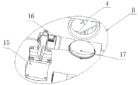
fig. 7 is a schematic structural view of a portion B in fig. 6.
In the figure: the device comprises a track 1, a mixing tank 2, a tank door 3, a discharge opening 4, a pulley 5, a support 6, a motor 7, a speed reducer 8, a rotating arm 9, a plough type blade 10, a lantern ring 11, a screw 12, a sleeve 13, a fixing clamp 14, a rotary cylinder 15, a spline 16, a plugging block 17 and a door handle 18.
Detailed Description
In order to make the technical means, the creation features, the achievement purposes and the functions of the present invention easy to understand and understand, the present invention is further explained by combining the following specific drawings.
As shown in fig. 1-7, the fully open type cleaning mixer comprises a track 1 and a mixing tank 2 fixedly arranged on the track 1, wherein a tank door 3 is respectively arranged on the top and one side wall of the mixing tank 2 through hinges, a sliding component is connected with a stirring component on the track 1 in a sliding manner, and the stirring component is also provided with a tank door 3 and is used for plugging or opening the other side wall of the mixing tank 2, a positioning component is further arranged on the track 1 and is used for determining the positions of the stirring component and the tank door 3, which are arranged on the mixing tank 2, when the stirring component is assisted by the sliding component, on one hand, the positioning component is utilized, a discharge opening 4 is arranged at the bottom of the mixing tank 2, and a discharge component is further arranged at the bottom of the mixing tank 2 and is used for plugging or opening the discharge opening 4.
The sliding assembly comprises a pulley 5 and a bracket 6, wherein the pulley 5 is arranged at the bottom of the bracket 6 and is connected on the track 1 in a sliding manner.
The stirring subassembly includes motor 7, speed reducer 8 with motor 7 cooperation use, rocking arm 9, plough paddle 10, the stiff end fixed mounting of speed reducer 8 with motor 7 cooperation use is on support 6, be used for the output of the output drive speed reducer 8 of motor 7 to rotate, the one end of rocking arm 9 rotates the cover on support 6, and fixed with the output of the speed reducer 8 with motor 7 cooperation use, the other end of rocking arm 9 still rotates the cover and is equipped with jar door 3, and stretch into the inside of blending tank 2, plough paddle 10 is fixed on rocking arm 9, and be located the inside of blending tank 2.
The positioning assembly comprises a lantern ring 11, a screw rod 12 and a sleeve 13, the lantern ring 11 is fixed on the sliding rail, the screw rod 12 is sleeved on the lantern ring 11 in a threaded mode, the sleeve 13 is fixed on the support 6, and the lantern ring 11 is also provided with a threaded hole;
when the screw 12 is sleeved on the lantern ring 11 and the sleeve 13 in a co-threaded manner, the tank door 3 is blocked on one side wall of the mixing tank 2, and one end of the rotating arm 9 and the plough-type paddle 10 are positioned inside the mixing tank 2.
The mixing tank 2 is also provided with a fixing clamp 14, and when the tank door 3 is closed on the mixing tank 2, the tank door 3 is fixed on the mixing tank 2 by the fixing clamp 14.
The subassembly of unloading includes revolving cylinder 15, spline 16 and shutoff piece 17, and revolving cylinder 15's stiff end fixed mounting is in the bottom of blending tank 2, and spline 16 rotates the cover and establishes on discharge opening 4, and revolving cylinder 15's output and the one end tip of spline 16 contact, and shutoff piece 17 is fixed to be established on spline 16 to with discharge opening 4 phase-match.
It should be noted that: the output end of the rotary cylinder 15 is in contact with the end of the spline 16 (the rotary cylinder 15 is arranged perpendicular to the axis of the spline 16).
The tank door 3 positioned at the top of the mixing tank 2 comprises two tank separating doors, one end of one tank separating door is hinged with the other tank separating door, the other tank separating door is hinged with the side wall of the mixing tank 2, and a door handle 18 is further arranged on one tank separating door.
The working principle is as follows:
firstly, opening a tank door 3 positioned on the top and one side wall of a mixing tank 2, thereby realizing the opening of the top and one side wall of the mixing tank 2;
then, the screw 12 is unscrewed again to separate the screw 12 from the sleeve 13, then the fixing clamp 14 is opened again, the bracket 6 is manually pushed to slide on the rail 1 under the sliding connection of the pulley 5 and the rail 1, so that the stirring assembly and the other tank door 3 are separated from the mixing tank 2 together, and then the mixing tank 2 and the rotating arm 9 and the plough-type blade 10 which are separated from the mixing tank 2 are manually cleaned by using a hose;
in addition, the discharging assembly works in the following mode: and starting the rotary cylinder 15, wherein the movable end of the rotary cylinder 15 drives the spline 16 to rotate on the mixing tank 2, so that the plugging block 17 is driven to plug or open the discharge opening 4.
The basic principles and the main features of the invention and the advantages of the invention have been shown and described above. It should be understood by those skilled in the art that the present invention is not limited to the above embodiments, and that various changes and modifications may be made without departing from the spirit and scope of the invention, and such changes and modifications fall within the scope of the claimed invention. The scope of the invention is defined by the appended claims and equivalents thereof.
Claims (7)
1. Full open type washs and mixes machine, including the track with fixed blending tank who establishes on the track, its characterized in that: the utility model discloses a mixing tank, including the mixing tank, still a section of thick bamboo slip subassembly sliding connection has the stirring subassembly, just on the top of mixing tank and a lateral wall respectively through the hinge be equipped with jar door, still be equipped with a jar door on the track, just also be equipped with a jar door on the stirring subassembly for on another lateral wall of the mixing tank is opened in the shutoff, still be equipped with locating component on the track, be used for when the stirring subassembly under the slip subassembly is supplementary, utilize locating component to confirm the position on the mixing tank of stirring subassembly and jar door installation on the one hand, the bottom of mixing tank is equipped with the discharge opening, the bottom of mixing tank still is equipped with the subassembly of unloading for the shutoff or open the discharge opening.
2. The fully open cleaning mixer of claim 1 wherein: the sliding assembly comprises a pulley and a support, and the pulley is arranged at the bottom of the support and is connected to the rail in a sliding mode.
3. The fully open cleaning mixer of claim 2 wherein: stirring subassembly includes the motor, uses speed reducer, rocking arm, plough paddle with the motor cooperation, the stiff end fixed mounting of the speed reducer that uses with the motor cooperation is on the support for output by the output drive speed reducer of motor rotates, the one end of rocking arm rotates the cover on the support to and fixed mutually with the output of the speed reducer that uses with the motor cooperation, the other end of rocking arm still rotates the cover and is equipped with the jar door to stretch into the inside of blending tank, the plough paddle is fixed on the rocking arm to be located the inside of blending tank.
4. The fully open cleaning mixer of claim 3 wherein: the positioning assembly comprises a lantern ring, a screw and a sleeve, the lantern ring is fixed on the slide rail, the screw is sleeved on the lantern ring in a threaded manner, the sleeve is fixed on the support, and the lantern ring is also provided with a threaded hole;
when the screw rods are sleeved on the lantern ring and the sleeve in a threaded manner, the tank door is sealed on one side wall of the mixing tank, and one end of the rotating arm and the plough-type blade are positioned in the mixing tank.
5. The fully open cleaning mixer of claim 1 wherein: the mixing tank is also provided with a fixing clamp, and when the tank door is closed on the mixing tank, the tank door is fixed on the mixing tank by the fixing clamp.
6. The fully open cleaning mixer of claim 1 wherein: the subassembly of unloading includes revolving cylinder, spline and shutoff piece, revolving cylinder's stiff end fixed mounting is in the bottom of blending tank, the spline rotates the cover and establishes on the discharge opening, just revolving cylinder's output and the one end tip of spline contact, the shutoff piece is fixed to be established on the spline to with the discharge opening phase-match.
7. The fully open cleaning mixer of claim 1 wherein: the tank door positioned at the top of the mixing tank comprises two tank separating doors, one end of one tank separating door is hinged with the other tank separating door, the other tank separating door is hinged with the side wall of the mixing tank, and a door handle is further arranged on one tank separating door.
Priority Applications (1)
| Application Number | Priority Date | Filing Date | Title |
|---|---|---|---|
| CN202120328023.0U CN214598480U (en) | 2021-02-05 | 2021-02-05 | Full open type cleaning mixer |
Applications Claiming Priority (1)
| Application Number | Priority Date | Filing Date | Title |
|---|---|---|---|
| CN202120328023.0U CN214598480U (en) | 2021-02-05 | 2021-02-05 | Full open type cleaning mixer |
Publications (1)
| Publication Number | Publication Date |
|---|---|
| CN214598480U true CN214598480U (en) | 2021-11-05 |
Family
ID=78440985
Family Applications (1)
| Application Number | Title | Priority Date | Filing Date |
|---|---|---|---|
| CN202120328023.0U Active CN214598480U (en) | 2021-02-05 | 2021-02-05 | Full open type cleaning mixer |
Country Status (1)
| Country | Link |
|---|---|
| CN (1) | CN214598480U (en) |
-
2021
- 2021-02-05 CN CN202120328023.0U patent/CN214598480U/en active Active
Similar Documents
| Publication | Publication Date | Title |
|---|---|---|
| CN107471447B (en) | A kind of construction concrete swing rotary formula agitating device | |
| CN211216303U (en) | Mixing stirring device for lubricating oil processing | |
| CN214598480U (en) | Full open type cleaning mixer | |
| CN214810340U (en) | Food processing raw material stirring device | |
| CN218590401U (en) | High-efficient agitating unit | |
| CN218077474U (en) | Mixing barrel convenient to clean | |
| CN212758078U (en) | Yoghourt emulsifying device | |
| CN208098830U (en) | A kind of vacuum kneader | |
| CN220159775U (en) | Sealant mixing drum with automatic cleaning function | |
| CN209934646U (en) | Mixer for experiments convenient to clearance | |
| CN208406827U (en) | Blender is used in a kind of test of grouting agent | |
| CN112844282A (en) | Liquid raw material reaction device | |
| CN205435599U (en) | V -shaped mixer | |
| CN211941479U (en) | Discharge port of air-entraining block adhesive stirring device | |
| CN213528441U (en) | High-efficient mixer that mixes of organosilicon | |
| CN217140084U (en) | Textile dye stirring machine for spinning | |
| CN217573455U (en) | A mixer for concrete is tried on | |
| CN218131132U (en) | Stirred tank convenient to material homogeneous mixing prevents sticking wall | |
| CN211936649U (en) | V type mixes machine convenient to it is clean | |
| CN219540021U (en) | Anti-blocking device for batching tank | |
| CN212119842U (en) | Stirring machine | |
| CN205418676U (en) | Concrete bucket's radial gate switch structure | |
| CN219334050U (en) | Easy-to-use type mixing equipment | |
| CN215610834U (en) | Low-speed mixer convenient to clean | |
| CN208118125U (en) | Blender is used in a kind of test of grouting agent |
Legal Events
| Date | Code | Title | Description |
|---|---|---|---|
| GR01 | Patent grant | ||
| GR01 | Patent grant |