CN214570013U - Turnover device for box-shaped component - Google Patents
Turnover device for box-shaped component Download PDFInfo
- Publication number
- CN214570013U CN214570013U CN202120193123.7U CN202120193123U CN214570013U CN 214570013 U CN214570013 U CN 214570013U CN 202120193123 U CN202120193123 U CN 202120193123U CN 214570013 U CN214570013 U CN 214570013U
- Authority
- CN
- China
- Prior art keywords
- lifting
- hook
- box
- main body
- lifting hook
- Prior art date
- Legal status (The legal status is an assumption and is not a legal conclusion. Google has not performed a legal analysis and makes no representation as to the accuracy of the status listed.)
- Active
Links
Images


Landscapes
- Load-Engaging Elements For Cranes (AREA)
Abstract
The utility model discloses a turning device for box type components, which comprises two lifting hooks, wherein each lifting hook comprises a rectangular plate-shaped lifting hook main body, a hook body part is arranged on the inner side of the lower end part of each lifting hook main body, a bent part is arranged at the upper end of each lifting hook main body, the top end of each bent part is connected with a lifting ring part, and a circular lifting hole is arranged inside each lifting ring part; the two lifting hooks are connected through a hinge barrel, the hinge barrel comprises a cylindrical barrel body, annular barrier strips are respectively arranged on the outer sides of two end parts of the barrel body, and the outer diameter of each annular barrier strip is equal to that of the lifting ring part; the bending part of the lifting hook is provided with two compression springs; the utility model provides a turnover device for box type members, which can realize the safety and high efficiency of the box type member hoisting and turnover process; the lifting appliance is not damaged in the lifting and turning process, and the service life of the lifting appliance can be prolonged.
Description
Technical Field
The utility model relates to a lifting device, specific theory relates to a turning device for box component, belongs to lifting device technical field.
Background
At present, the preparation of box component has become one of the common steel member of steel construction company's preparation processing, in the production manufacture process we can often meet the hoist and mount work of box that will overturn, and the mill is when the hoist and mount is implemented to the upset box, mostly adopts for following two kinds of modes:
the first is to adopt a sling or a sling chain to perform binding type overturning, and a binding type hoisting overturning component is solid and convenient, but the following defects exist in the binding type overturning: a certain time is consumed in the binding process, so that the hoisting and overturning efficiency is too low; the edges and corners of the box-shaped members can damage the lifting belts or the lifting chains in the overturning process, the service life of the lifting belts or the lifting chains which are hoisted can be greatly shortened by frequent use, the slipping risk exists in addition, and the potential safety hazard of the overturning operation is large.
The second kind is the end that adopts the hanging tong to turn over the case type component, and this kind of mode also has great risk, and the hanging tong breaks away from the component easily, needs artifical the support before lifting by crane, treats that the hanging tong atress back, the staff is leaving the hoist and mount region, and the potential safety hazard of upset operation is great, and this kind of hoist and mount mode still produces certain noise in addition.
In view of the above, the prior art is obviously inconvenient and disadvantageous in practical use, and needs to be improved.
SUMMERY OF THE UTILITY MODEL
The utility model provides a turnover device for box type components, aiming at the defects in the background technology, which can realize the safety and high efficiency of the box type component hoisting and turnover process; the lifting appliance is not damaged in the lifting and turning process, and the service life of the lifting appliance can be prolonged.
For solving the technical problem, the utility model discloses a following technical scheme:
a turnover device for a box-type component comprises two lifting hooks, wherein each lifting hook comprises a rectangular plate-shaped lifting hook main body, and a hook body part is arranged on the inner side of the lower end part of each lifting hook main body; the upper end of the lifting hook main body is provided with a bent part, the top end of the bent part is connected with the lifting ring part, and a circular lifting hole is formed in the lifting ring part; the two lifting hooks are connected through a hinge barrel, the hinge barrel comprises a cylindrical barrel body, annular barrier strips are respectively arranged on the outer sides of two end parts of the barrel body, and the outer diameter of each annular barrier strip is equal to that of the lifting ring part; and the bending part of the lifting hook is provided with two compression springs.
Further, the upper surface of the hook body and the hook main body are arranged at an included angle of 90 degrees.
Furthermore, the upper surface of the hook body part is provided with a friction surface, and strip-shaped grooves which are criss-cross are arranged in the friction surface.
Further, the hook main body, the hook body portion, the bent portion, and the hanging ring portion are integrally formed.
Further, the external diameter of barrel is less than the internal diameter of lewis hole, and the barrel is worn to establish in the hoisting ring portion.
Further, the two hooks can rotate along the hinge barrel.
Furthermore, one end of the compression spring is fixedly connected with the bent part of one lifting hook, and the other end of the compression spring is fixedly connected with the bent part of the other lifting hook.
The utility model adopts the above technical scheme after, compare with prior art, have following advantage:
before hoisting, the utility model struts and clamps the two lifting hooks to the surface of the box-shaped member to two sides, the lifting hooks are attached to the surface of the box-shaped member under the spring tension, the two lifting hooks are matched to realize the overturning of the box-shaped member, and the safety and the high efficiency of the hoisting and overturning process of the box-shaped member are realized; the utility model does not damage the lifting appliance during the lifting and turning process, and can effectively prolong the service life of the lifting appliance; the utility model discloses there is not the noise basically at hoist and mount upset in-process.
The present invention will be described in detail with reference to the accompanying drawings and examples.
Drawings
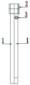
FIG. 1 is a front view of the structure of the present invention;
fig. 2 is a side view of the structure of the present invention;
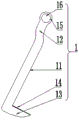
FIG. 3 is a schematic view of the structure of the hook of the present invention;
FIG. 4 is a partial cross-sectional structural view of FIG. 2;
FIG. 5 is a schematic view of the present invention during the hoisting process;
in the figure, 1-hook, 11-hook body, 12-bending part, 13-hook body, 14-friction surface, 15-hanging ring part and 16-hanging hole; 2-hinge cylinder, 21-cylinder, 22-ring barrier strip; 3-compression spring, 4-box type member.
Detailed Description
In order to clearly understand the technical features, objects, and effects of the present invention, embodiments of the present invention will be described with reference to the accompanying drawings.
As shown in fig. 1-4, the utility model provides a turning device for box-type members, which comprises two hooks 1;
the lifting hook 1 comprises a rectangular plate-shaped lifting hook main body 11, a hook body 13 is arranged on the inner side of the lower end part of the lifting hook main body 11, and an included angle of 90 degrees is formed between the upper surface of the hook body 13 and the lifting hook main body 11.
The upper surface of the hook body 13 is provided with a friction surface 14, the friction surface 14 is internally provided with criss-cross strip-shaped grooves, and the friction surface 14 has a certain anti-skidding function in the hoisting process.
The upper end of lifting hook main part 11 is provided with kink 12, and the top and the rings portion 15 of kink 12 are connected, and rings portion 15 inside is equipped with circular lewis hole 16.
The hook body 11, the hook body portion 13, the bent portion 12, and the hanging ring portion 15 are integrally formed.
The two lifting hooks 1 are connected through a hinge barrel 2, the hinge barrel 2 comprises a cylindrical barrel body 21, the outer diameter of the barrel body 21 is smaller than the inner diameter of the lifting hole 16, and the barrel body 21 penetrates through the lifting ring part 15; the outer sides of two end parts of the cylinder 21 are respectively provided with an annular barrier strip 22, and the outer diameter of the annular barrier strip 22 is equal to that of the hanging ring part 15.
The two lifting hooks 1 can rotate along the hinge barrel 2, and the hinge barrel 2 can be connected with the shackle.
The bending part 12 of the lifting hook 1 is provided with two compression springs 3; one end of the compression spring 3 is fixedly connected with the bent part 12 of one of the lifting hooks 1, and the other end of the compression spring 3 is fixedly connected with the bent part 12 of the other lifting hook 1.
The compression spring 3 can make the lifting hook 1 receive a tensile force towards the middle when the two lifting hooks 1 open and close towards two sides, so that the lifting hook main body 11 of the lifting hook 1 is attached to the surface of the box-shaped member 4, and the lifting hook 1 is convenient to mount; the compression spring 3 can accommodate the hook 1 toward the center to reduce the occupied area of the hook 1.
The utility model discloses a concrete theory of operation:
before hoisting, the utility model manually props the two lifting hooks 1 to two sides, so that the compression spring 3 is stretched, the two lifting hooks 1 are clamped on the surface of the box-shaped member 4, and the lifting hook main bodies 11 of the lifting hooks 1 are attached on the surface of the box-shaped member 4 under the tension of the compression spring 3 by the two lifting hooks 1; then through wire rope and shackle lifting hinge section of thick bamboo 2 department, need not artifical support lifting hook 1 during lifting by crane, two lifting hooks 1 cooperate and realize the upset to box component 4, and the in-process friction surface 14 of upset plays certain anti-skidding effect, and the in-process of upset does not have the noise basically, struts two lifting hooks 1 to both sides through the manpower after the upset, take off lifting hook 1 can.
The foregoing is illustrative of the best mode of the invention, and details not described herein are within the common general knowledge of a person of ordinary skill in the art. The protection scope of the present invention is subject to the content of the claims, and any equivalent transformation based on the technical teaching of the present invention is also within the protection scope of the present invention.
Claims (7)
1. A turning device for box component, includes two lifting hooks (1), its characterized in that: the lifting hook (1) comprises a rectangular plate-shaped lifting hook main body (11), and a hook body part (13) is arranged on the inner side of the lower end part of the lifting hook main body (11); the upper end of the lifting hook main body (11) is provided with a bent part (12), the top end of the bent part (12) is connected with a lifting ring part (15), and a circular lifting hole (16) is formed in the lifting ring part (15); the two lifting hooks (1) are connected through a hinge barrel (2), the hinge barrel (2) comprises a cylindrical barrel body (21), annular barrier strips (22) are respectively arranged on the outer sides of two end parts of the barrel body (21), and the outer diameter of each annular barrier strip (22) is equal to that of the lifting ring part (15); and the bending part (12) of the lifting hook (1) is provided with two compression springs (3), and the number of the compression springs (3) is two.
2. A turnover device for box-type elements according to claim 1, characterised in that: the upper surface of the hook body part (13) and the hook main body (11) are arranged at an included angle of 90 degrees.
3. A turnover device for box-type elements according to claim 1, characterised in that: the upper surface of the hook body part (13) is provided with a friction surface (14), and the friction surface (14) is internally provided with criss-cross strip-shaped grooves.
4. A turnover device for box-type elements according to claim 1, characterised in that: the lifting hook comprises a lifting hook main body (11), a hook body part (13), a bending part (12) and a lifting ring part (15) which are integrally formed.
5. A turnover device for box-type elements according to claim 1, characterised in that: the outer diameter of the cylinder body (21) is smaller than the inner diameter of the lifting hole (16), and the cylinder body (21) penetrates through the lifting ring part (15).
6. A turnover device for box-type elements according to claim 1, characterised in that: the two lifting hooks (1) can rotate along the hinge barrel (2).
7. A turnover device for box-type elements according to claim 1, characterised in that: one end of the compression spring (3) is fixedly connected with the bending part (12) of one lifting hook (1), and the other end of the compression spring (3) is fixedly connected with the bending part (12) of the other lifting hook (1).
Priority Applications (1)
| Application Number | Priority Date | Filing Date | Title |
|---|---|---|---|
| CN202120193123.7U CN214570013U (en) | 2021-01-25 | 2021-01-25 | Turnover device for box-shaped component |
Applications Claiming Priority (1)
| Application Number | Priority Date | Filing Date | Title |
|---|---|---|---|
| CN202120193123.7U CN214570013U (en) | 2021-01-25 | 2021-01-25 | Turnover device for box-shaped component |
Publications (1)
| Publication Number | Publication Date |
|---|---|
| CN214570013U true CN214570013U (en) | 2021-11-02 |
Family
ID=78370799
Family Applications (1)
| Application Number | Title | Priority Date | Filing Date |
|---|---|---|---|
| CN202120193123.7U Active CN214570013U (en) | 2021-01-25 | 2021-01-25 | Turnover device for box-shaped component |
Country Status (1)
| Country | Link |
|---|---|
| CN (1) | CN214570013U (en) |
Cited By (1)
| Publication number | Priority date | Publication date | Assignee | Title |
|---|---|---|---|---|
| CN114557559A (en) * | 2022-03-31 | 2022-05-31 | 北京物智链科技有限公司 | Turnover device of folding device |
-
2021
- 2021-01-25 CN CN202120193123.7U patent/CN214570013U/en active Active
Cited By (1)
| Publication number | Priority date | Publication date | Assignee | Title |
|---|---|---|---|---|
| CN114557559A (en) * | 2022-03-31 | 2022-05-31 | 北京物智链科技有限公司 | Turnover device of folding device |
Similar Documents
| Publication | Publication Date | Title |
|---|---|---|
| CN201598100U (en) | Anti-curl device for steel plate clamp suspension system | |
| CN2931423Y (en) | Steel pipe combined hanger | |
| CN214570013U (en) | Turnover device for box-shaped component | |
| CN203820283U (en) | Lifting frame | |
| CN203513086U (en) | Special lifting appliance for long-bundle-shaped material | |
| CN207581194U (en) | For the boom hoisting of pivoting support | |
| CN207774605U (en) | A kind of unit module hoisting fixture for outfititem | |
| CN205973449U (en) | Jack -up handling rigging of buffering pulley | |
| CN202575689U (en) | Tree trunk lifting tool | |
| CN209113350U (en) | A kind of safe suspender of ring forging | |
| CN204416919U (en) | A kind of lifting device | |
| CN201605087U (en) | Goods hoisting device | |
| CN101734549A (en) | Lifting sling | |
| CN204999498U (en) | Large tracts of land sheet metal presss from both sides tight hoist cable device | |
| CN201619944U (en) | Sling instrument | |
| CN206872264U (en) | Lift aid | |
| CN201961955U (en) | Dual C-shaped lifting sling for rolling plate | |
| CN205011223U (en) | Middle -size and small -size rolling -mill housing installation hoist | |
| CN2835186Y (en) | Sling for loading and unloading aluminum ingot | |
| CN205709453U (en) | A kind of line bar handling folder | |
| CN214298880U (en) | Ton bucket hook | |
| CN204847790U (en) | Novel lifting hook is used to hoist | |
| CN204643580U (en) | Cement pole lifting chuck device | |
| CN210528239U (en) | Lifting hook for unloading coiled anchor cable | |
| CN217894877U (en) | Self-sealing type bidirectional lifting hook |
Legal Events
| Date | Code | Title | Description |
|---|---|---|---|
| GR01 | Patent grant | ||
| GR01 | Patent grant |