CN214569570U - Automatic material machine of receiving of mixed piece of play of rubber and plastic - Google Patents
Automatic material machine of receiving of mixed piece of play of rubber and plastic Download PDFInfo
- Publication number
- CN214569570U CN214569570U CN202120558056.4U CN202120558056U CN214569570U CN 214569570 U CN214569570 U CN 214569570U CN 202120558056 U CN202120558056 U CN 202120558056U CN 214569570 U CN214569570 U CN 214569570U
- Authority
- CN
- China
- Prior art keywords
- sheet
- rubber
- belt
- adsorption type
- type conveying
- Prior art date
- Legal status (The legal status is an assumption and is not a legal conclusion. Google has not performed a legal analysis and makes no representation as to the accuracy of the status listed.)
- Active
Links
Images


Abstract
The utility model relates to an automatic receiving machine for rubber and plastic mixed sheet discharging, which comprises a frame, wherein an adsorption type conveying belt for adsorbing and conveying sheets is erected on the frame, the adsorption type conveying belt is positioned above the sheet material, a material receiving mechanism for collecting the sheet material is arranged below the adsorption type conveying belt, the machine frame is also provided with a blanking push plate for pushing the sheet material off the adsorption type conveying belt and a blanking mechanism for driving the blanking push plate to move, the discharging push plate is positioned above the material receiving mechanism, the material receiving mechanism is arranged below the adsorption type conveying belt, so that the occupied area of the material receiving mechanism is reduced in space, the space utilization rate of the whole equipment is improved, and collect the sheet with the throwing mode that pushes away the mode and replace traditional conveyer belt, effectively avoid the sheet to collect and bend and be in disorder because of throwing the cause.
Description
Technical Field
The utility model relates to a rubber and plastic processing technology field, the more specifically indicate that a material machine is received in the mixed piece automation of going out of rubber and plastic.
Background
The rubber and plastic mixed sheet is produced by mixing the plastic rice, the rubber and the compounding agent with a rubber mixing mill to produce mixed rubber, cooling and cutting into sheets matched with the mold by a rubber and plastic sheet producing machine. After the rubber and plastic sheet discharging machine on the market cuts the sheet, the sheet is usually conveyed to a collecting box through a conveying belt and guided into the collecting box by a guide plate for collection and storage. However, since the collecting box is usually disposed at the end of the conveying belt, the collecting box must occupy a certain space from a top view, so that the whole production chain occupies a large area and has a low space utilization rate. Therefore, the traditional sheets are usually thrown into the collecting box under the inertia effect of the conveying belt or naturally slide into the collecting box, and the sheet collection is messy and inconvenient to arrange, and the sheet bending phenomenon is easy to occur, so that the quality of the sheets cannot be guaranteed.
SUMMERY OF THE UTILITY MODEL
The utility model provides an automatic material machine of receiving of mixed piece of play of rubber and plastic to it is big to solve rubber and plastic play mascerating machine receiving agencies area among the prior art, and the sheet is collected in disorder easy scheduling problem of buckling.
The utility model adopts the following technical scheme:
the utility model provides an automatic material machine of receiving of mixed piece of rubber and plastic, includes the frame, the frame is put up and is used for adsorbing the sheet and the absorption formula conveyer belt of transmission, the absorption formula conveyer belt is located the sheet top, absorption formula conveyer belt below is equipped with the receiving agencies who is used for collecting the sheet, still be equipped with in the frame and be used for the unloading push pedal that the sheet pushed away from the absorption formula conveyer belt and drive the unloading mechanism of this unloading push pedal action, the unloading push pedal is located receiving agencies's top.
Further, the adsorption type conveyer belt is two adsorption type conveyer belts arranged in parallel, and the two adsorption type conveyer belts are respectively positioned above two sides of the sheet.
Further, the adsorption type conveying belt comprises a belt, a transmission wheel and a servo motor, the transmission wheel is in belt transmission, the servo motor drives the transmission wheel to rotate, a plurality of ventilation holes are formed in the belt in a hollowed-out mode, a sealing air groove is formed in the belt and close to one side of the sheet, a plurality of air suction holes are formed in the sealing air groove in a hollowed-out mode and face to one side of the sheet, and an air pump is further connected to the sealing air groove.
Furthermore, a plurality of air outlets are arranged at one side of the sealed air groove at intervals, the air outlets are respectively connected with the air pump, and an air valve is correspondingly arranged on each air outlet.
Further, the unloading push pedal is located between two absorption formula conveyer belts to pass repeatedly and push away the sheet between two absorption formula conveyer belts and fall, unloading mechanism includes eccentric wheel, connecting rod, push rod, linear slide and is used for driving the rotatory servo motor of eccentric wheel, servo motor and linear slide fixed mounting in the frame, the push rod passes linear slide with unloading push pedal fixed connection, the connecting rod both ends respectively with eccentric wheel and push rod are articulated.
Further, the receiving mechanism is a trolley for storing the sheets.
Furthermore, the trolley at least comprises two stations for storing sheets, and the trolley and the adsorption type conveying belt are arranged in a cross mode.
Furthermore, a numerical control lifting platform is arranged on the trolley, and the sheet is placed on the numerical control lifting platform.
From the above description of the structure of the present invention, compared with the prior art, the present invention has the following advantages:
1. the utility model discloses an absorption formula conveyer belt transmits the sheet to set up receiving agencies in absorption formula conveyer belt below, adopt the unloading push pedal to push off the sheet from absorption formula conveyer belt and collect to receiving agencies, not only reduced receiving agencies's area in the space, improved the space utilization of equipment, collect the sheet with the mode of jettisoning that the mode of jettisoning replaced traditional conveyer belt in addition, effectively avoid sheet to collect and concentrate because of throwing the bending that causes and in disorder.
2. The utility model discloses during absorption formula conveyer belt transmission sheet, sealed air duct passes through a plurality of air outlet and the air valve cooperation of interval arrangement, divide into a plurality of transmission section, and the switch through the control pneumatic valve, thereby control the suction of each transmission section, and then the transmission of cooperation sheet on absorption formula conveyer belt, be promptly at the sheet when through which one section of absorption formula conveyer belt, open the pneumatic valve that corresponds, and close other pneumatic valves, even make absorption formula conveyer belt prolong the transport distance, also can keep sufficient adsorption affinity to transmit the sheet, and need not additionally to increase the power of air pump.
3. The utility model discloses receiving agencies is the shallow, includes two stations that are used for depositing the sheet on the shallow at least, and the shallow is the cross with the absorption formula conveyer belt and arranges, after one of them station of shallow has been deposited with the sheet, only needs the pulling shallow, lets out next station and continues to deposit the sheet, can shift the sheet on the station that has been deposited with the sheet simultaneously, and then improves the collection efficiency and the transfer efficiency of sheet.
4. The utility model discloses at the sheet in-process that drops, the interval that the shallow still can keep the sheet to drop through numerical control elevating platform, drops along with the sheet piece by piece promptly, and numerical control elevating platform descends gradually to prevent that the sheet from producing upset, displacement because of the dropping distance overlength, and cause phenomenons such as buckle, in disorder.
Drawings
FIG. 1 is a front view of the automatic material receiving production line of the present invention;
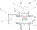
fig. 2 is a front view of the automatic material receiving machine after the default frame of the utility model is arranged;
FIG. 3 is a sectional view taken along line A-A of FIG. 2;
fig. 4 is the structural schematic diagram of the sealing air duct of the present invention.
Wherein the reference numbers in the figures are: the automatic material collecting machine comprises a slicing machine 1, a variable-speed conveying belt 2, an automatic material collecting machine 3, a sheet 4, a machine frame 31, an adsorption type conveying belt 32, a belt 321, a vent hole 322, a driving wheel 323, a sealing air groove 324, an air suction hole 325, an air outlet 326, an air pipe 327, an air valve 328, a blanking mechanism 33, a blanking push plate 331, an eccentric wheel 332, a connecting rod 333, a push rod 334, a linear slide rail 335, a material collecting mechanism 34, a trolley 341, a trolley guide rail 342 and a numerical control lifting platform 343.
Detailed Description
The following describes specific embodiments of the present invention with reference to the drawings.
Referring to fig. 1, an automatic material production line of receiving of mixed piece of rubber and plastic, including slicer 1, variable speed conveyer belt 2 and automatic material machine 3 of receiving, the sheet 4 that the mixed piece of rubber and plastic goes out loops through slicer 1, variable speed conveyer belt 2 and automatic material machine 3 of receiving carries out section, transmission and receipts material. In this embodiment, the slicer 1 and the variable speed conveyer belt 2 are the conventional rubber-plastic mixing slice-discharging slicer 1 and the variable speed conveyer belt 2, and the structure and the operation principle thereof are common knowledge for those skilled in the art, and are not described herein again. Automatic material receiving machine 3 includes frame 31, frame 31 is put on the shelf and is used for adsorbing and the absorption formula conveyer belt 32 of transmission with sheet 4, absorption formula conveyer belt 32 is located sheet 4 top, and absorption formula conveyer belt 32 one end is upper and lower staggered arrangement with the other end of variable speed conveyer belt 2, absorption formula conveyer belt 32 below is equipped with the receiving agencies 34 that is used for collecting sheet 4, still be equipped with the unloading push pedal 331 that is used for pushing away sheet 4 from absorption formula conveyer belt 32 and the unloading mechanism 33 of this unloading push pedal 331 action of drive on the frame 31, unloading push pedal 331 is located the top of receiving agencies 34.
More specifically, referring to fig. 2 to 4, the adsorption type conveyor 32 is two adsorption type conveyor 32 disposed in parallel, and the two adsorption type conveyor 32 are respectively located above both sides of the sheet 4 and are used for adsorbing and conveying the sheet 4. The suction conveyer 32 includes a belt 321, a driving wheel 323 stretching and driving the belt 321, and a servo motor (not shown) driving the driving wheel 323 to rotate. The belt 321 is hollowed with a plurality of ventilation holes 322, a sealing air groove 324 is arranged in the belt 321 near one side of the sheet 4, a plurality of air suction holes 325 are hollowed in the sealing air groove 324 facing one side of the sheet 4, a plurality of air outlets 326 are arranged at intervals on one side of the sealing air groove 324, the air outlets 326 are respectively connected with an air pump (not shown in the figure) through an air pipe 327, and an air valve 328 is arranged on the air pipe 327 corresponding to each air outlet 326.
Referring to fig. 2 to 4, the sealing air duct 324 is fixed to the frame 31, and is evacuated by the air pump to form a negative pressure, and is sucked through a plurality of suction holes 325 facing one side of the sheet 4, and forms an adsorption type conveyor belt 32 capable of adsorbing and conveying the sheet 4 in cooperation with a belt 321 having the suction holes 322. When the adsorption type conveying belt 32 conveys the sheet 4, the sealing air groove 324 is matched with the air valve 328 through the air outlets 326 arranged at intervals, and is divided into a plurality of conveying sections, and the suction force of each conveying section is controlled through controlling the opening and closing of the air valve 328, so that the sheet 4 is matched with the conveying on the adsorption type conveying belt 32. For example, in this embodiment, the three air outlets 326 and the three air valves 328 are disposed on the sealing air duct 324, so that the sealing air duct 324 and the adsorption type conveying belt 32 are divided into three sections, and when the sheet 4 passes through any section of the adsorption type conveying belt 32, the corresponding air valve 328 is opened, and the other two air valves 328 are closed, so that the adsorption type conveying belt 32 can maintain sufficient adsorption force to convey the sheet 4 even if the conveying distance is extended, and the power of the air pump does not need to be additionally increased.
Referring to fig. 2 to 4, the blanking mechanism 33 includes an eccentric 332, a connecting rod 333, a push rod 334, a linear guideway 335, and a servo motor (not shown) for driving the eccentric 332 to rotate, and the servo motor and the linear guideway 335 are fixedly mounted on the frame 31. The push rod 334 penetrates through the linear slide rail 335 to be fixedly connected with the blanking push plate 331, two ends of the connecting rod 333 are respectively hinged with the eccentric wheel 332 and the push rod 334, the blanking push plate 331 is located between the two adsorption type conveyor belts 32, the eccentric wheel 332 rotates to drive the push rod 334 to push, and the two adsorption type conveyor belts 32 move repeatedly, so that the sheets 4 on the adsorption type conveyor belts 32 are pushed down one by one.
Referring to fig. 2 to 4, the receiving mechanism 34 is a cart 341 for storing the sheets 4, the cart 341 includes at least two stations for storing the sheets 4, the cart 341 and the adsorption type conveyor 32 are arranged in a cross manner, and a cart guide 342 is correspondingly disposed below the cart 341. A numerically controlled lifting table 343 for placing the sheet 4 can be further provided on the cart 341 according to the requirement.
Referring to fig. 1 to 4, the operation flow of the production line is as follows, the rubber and plastic mixed sheet 4 passes through the slicer 1 for frequent slicing, and the distance between each sheet 4 is controlled by controlling the transmission speed of the variable speed conveyer belt 2. Then, the sheet 4 is conveyed onto the adsorption conveyor 32 for conveyance, and when the sheet 4 is conveyed to above the cart 341, the blanking push rod 334 is pressed down to push the sheet 4 off the adsorption conveyor 32 and drop the sheet 4 to one of the stations of the cart 341, so that the process is repeated, and after the station is full of sheets 4 on the cart 341, the cart 341 is pulled to leave the next station to continue to store the sheets 4, and the sheets 4 at the station full of sheets 4 are transferred and stored. In addition, in the dropping process of the sheet 4, the cart 341 may further maintain the dropping distance of the sheet 4 through the numerically controlled lifting platform 343, that is, as the sheet 4 drops one by one, the numerically controlled lifting platform 343 gradually drops, thereby preventing the sheet 4 from being turned over due to an excessively long dropping distance, and preventing the sheet from being bent.
The above-mentioned be the utility model discloses a concrete implementation way, nevertheless the utility model discloses a design concept is not limited to this, and the ordinary use of this design is right the utility model discloses carry out immaterial change, all should belong to the act of infringement the protection scope of the utility model.
Claims (8)
1. The utility model provides an automatic material machine of receiving of mixed piece of rubber and plastic, its characterized in that: the sheet material feeding device comprises a frame, the frame is put on the shelf and is used for adsorbing and transmitting the absorption formula conveyer belt with the sheet, the absorption formula conveyer belt is located the sheet top, and absorption formula conveyer belt below is equipped with the receiving agencies who is used for collecting the sheet, still be equipped with in the frame and be used for the unloading push pedal that pushes away the sheet from absorption formula conveyer belt and drive the unloading mechanism of this unloading push pedal action, the unloading push pedal is located receiving agencies's top.
2. The automatic receiving machine for the rubber and plastic mixed pieces as claimed in claim 1, wherein: the adsorption type conveying belt is two adsorption type conveying belts arranged in parallel, and the two adsorption type conveying belts are respectively positioned above two sides of the sheet.
3. The automatic receiving machine for the rubber and plastic mixed pieces as claimed in claim 1, wherein: the adsorption type conveying belt comprises a belt, a transmission wheel and a servo motor, the transmission wheel is driven by the belt in a tightening mode, the servo motor drives the transmission wheel to rotate, a plurality of ventilation holes are formed in the belt in a hollowed mode, a sealing air groove is formed in the belt and close to one side of a sheet, a plurality of air suction holes are formed in the sealing air groove in a hollowed mode towards one side of the sheet, and an air pump is further connected to the sealing air groove.
4. The automatic receiving machine for the rubber and plastic mixed pieces as claimed in claim 3, wherein: a plurality of air outlets are arranged on one side of the sealed air groove at intervals, the air outlets are respectively connected with the air pump, and an air valve is correspondingly arranged on each air outlet.
5. The automatic receiving machine for the rubber and plastic mixed pieces as claimed in claim 2, wherein: the unloading push pedal is located between two absorption formula conveyer belts to pass repeatedly and push away the sheet between two absorption formula conveyer belts and fall, unloading mechanism includes eccentric wheel, connecting rod, push rod, linear slide rail and is used for driving the rotatory servo motor of eccentric wheel, servo motor and linear slide rail fixed mounting in the frame, the push rod passes linear slide rail with unloading push pedal fixed connection, the connecting rod both ends respectively with eccentric wheel and push rod are articulated.
6. The automatic receiving machine for the rubber and plastic mixed pieces as claimed in claim 1, wherein: the receiving mechanism is a trolley for storing sheets.
7. The automatic receiving machine for the rubber and plastic mixed pieces as claimed in claim 6, wherein: the trolley at least comprises two stations for storing sheets, and the trolley and the adsorption type conveying belt are arranged in a cross mode.
8. The automatic receiving machine for the rubber and plastic mixed pieces as claimed in claim 6, wherein: the trolley is provided with a numerical control lifting platform, and the sheet is placed on the numerical control lifting platform.
Priority Applications (1)
| Application Number | Priority Date | Filing Date | Title |
|---|---|---|---|
| CN202120558056.4U CN214569570U (en) | 2021-03-18 | 2021-03-18 | Automatic material machine of receiving of mixed piece of play of rubber and plastic |
Applications Claiming Priority (1)
| Application Number | Priority Date | Filing Date | Title |
|---|---|---|---|
| CN202120558056.4U CN214569570U (en) | 2021-03-18 | 2021-03-18 | Automatic material machine of receiving of mixed piece of play of rubber and plastic |
Publications (1)
| Publication Number | Publication Date |
|---|---|
| CN214569570U true CN214569570U (en) | 2021-11-02 |
Family
ID=78354634
Family Applications (1)
| Application Number | Title | Priority Date | Filing Date |
|---|---|---|---|
| CN202120558056.4U Active CN214569570U (en) | 2021-03-18 | 2021-03-18 | Automatic material machine of receiving of mixed piece of play of rubber and plastic |
Country Status (1)
| Country | Link |
|---|---|
| CN (1) | CN214569570U (en) |
Cited By (1)
| Publication number | Priority date | Publication date | Assignee | Title |
|---|---|---|---|---|
| CN114370800A (en) * | 2021-12-31 | 2022-04-19 | 崇辉半导体(深圳)有限公司 | Alarm system is reminded to continuous electroplating production line material area soldered connection |
-
2021
- 2021-03-18 CN CN202120558056.4U patent/CN214569570U/en active Active
Cited By (1)
| Publication number | Priority date | Publication date | Assignee | Title |
|---|---|---|---|---|
| CN114370800A (en) * | 2021-12-31 | 2022-04-19 | 崇辉半导体(深圳)有限公司 | Alarm system is reminded to continuous electroplating production line material area soldered connection |
Similar Documents
| Publication | Publication Date | Title |
|---|---|---|
| CN207267753U (en) | Automatic feed mechanism | |
| CN214569570U (en) | Automatic material machine of receiving of mixed piece of play of rubber and plastic | |
| CN108016865A (en) | A kind of feed device of conveying sheet belt | |
| CN110356633B (en) | Automatic packaging device for clothes hanger | |
| CN213648613U (en) | Automatic plastic bottle blowing machine | |
| CN209183424U (en) | Press the automatic assembling of touch-switch in a kind of three-layer type side | |
| CN213504786U (en) | Carton discharge mechanism | |
| CN109573170A (en) | Full-automatic tobacco packet produces linked system | |
| CN206358809U (en) | A kind of waste collection systems in carton factory multilayer workshop | |
| CN208499459U (en) | A kind of feeding track of bracket class product | |
| CN112452701B (en) | Industrial material sorting device and using method thereof | |
| CN212653966U (en) | Bag conveying mechanism | |
| CN210553233U (en) | Full-automatic mosquito-repellent incense coil production device integrating forming and blank collection | |
| CN207551441U (en) | Individual waste paper output mechanism of full-automatic upper paper machine | |
| CN217946693U (en) | Intermittent type formula drop feed mechanism | |
| CN111169703A (en) | Package production line throws | |
| CN111392461A (en) | Servo synchronous film-sending mechanism | |
| CN213921811U (en) | Mask blanking device | |
| CN213474375U (en) | Discharging non-stop discharging device and cutting machine | |
| CN109390174A (en) | Press the automatic assembling of touch-switch in a kind of three-layer type side | |
| CN111099058A (en) | Double-station high-speed full-specification cigarette packaging machine | |
| CN213470428U (en) | Pneumatic type does not stop production discharging device and cutting machine | |
| CN219540986U (en) | Three-dimensional automatic selecting device for plates | |
| CN211678809U (en) | Differential separation commodity circulation sorting machine | |
| CN220663941U (en) | Automatic pipe discharging device |
Legal Events
| Date | Code | Title | Description |
|---|---|---|---|
| GR01 | Patent grant | ||
| GR01 | Patent grant |