CN214556486U - Automatic pipe bending device - Google Patents
Automatic pipe bending device Download PDFInfo
- Publication number
- CN214556486U CN214556486U CN202023209905.XU CN202023209905U CN214556486U CN 214556486 U CN214556486 U CN 214556486U CN 202023209905 U CN202023209905 U CN 202023209905U CN 214556486 U CN214556486 U CN 214556486U
- Authority
- CN
- China
- Prior art keywords
- sliding
- rotating shaft
- block
- connecting rod
- arc
- Prior art date
- Legal status (The legal status is an assumption and is not a legal conclusion. Google has not performed a legal analysis and makes no representation as to the accuracy of the status listed.)
- Active
Links
Images


Abstract
The utility model aims at providing an automatic pipe bending device, which comprises a workbench and a bending mechanism; the bending mechanism is arranged on the workbench; the bending mechanism comprises a sample conveying track, a clamping moving mechanism, a rotating driving mechanism, a mounting seat a, a material ejecting positioning block, a mounting seat b, a rotating shaft a, a rotating seat, a sliding chute b, a driving mechanism, a material ejecting block a and a material ejecting block b; and a sample conveying track which is horizontal along the front-back direction of the working table is arranged on the top surface of the working table. The utility model has the characteristics of structure scientific and reasonable, convenient operation, the precision of bending is high, degree of automation is high.
Description
Technical Field
The utility model relates to the field of mechanical equipment, concretely relates to automatic swan neck system.
Background
The automobile brake pipe, commonly called brake pipe, is a part used in an automobile brake system, and mainly has the main function of transmitting brake media in automobile braking to ensure that the brake force is transmitted to an automobile brake shoe or a brake caliper to generate brake force, so that the braking is effective at any time. The hard metal brake pipe must be bent in multiple points and multiple directions in order to meet the design of the interior structure of the vehicle. At present, mainly adopt the mould of bending among the prior art, design out the crooked work piece of each bending point according to concrete cast, mostly be the welding mode of assembling, structural accessory wherein is mostly the customization type, lead to bending the unable used repeatedly of accessory majority in the unit mechanism, belong to the special customization to a certain model motorcycle type basically, tooling mould manufacturing cost has been increased, and it is big to weld whole tooling mechanism deflection in the back, can't finely tune once more when follow-up debugging, make when bending the hard tube shaping precision relatively poor, and the human cost is high, and efficiency is lower.
Disclosure of Invention
The utility model aims at providing an automatic swan neck system, the device have structure scientific and reasonable, convenient operation, bend characteristics such as the precision is high, degree of automation height.
The technical scheme of the utility model as follows:
the automatic pipe bending device comprises a sample conveying track, a clamping and moving mechanism, a rotating driving mechanism, a mounting seat a, a material ejecting positioning block, a mounting seat b, a rotating shaft a, a rotating seat, a sliding groove b, a driving mechanism, a material ejecting block a and a material ejecting block b;
the top surface of the workbench is provided with a sample conveying track which is horizontal along the front-back direction;
the mounting seats a and b are arranged on the front end of the workbench side by side along the left and right; the mounting seat a is provided with a material ejecting positioning block, the right end face of the material ejecting positioning block is provided with an arc-shaped groove a corresponding to the shape of the pipe, and the axial direction of the arc-shaped groove a is parallel to the direction of the sample conveying track;
the workbench is provided with a rotary driving mechanism, the rotary shaft a is arranged on the front side of the mounting seat b through a shaft sleeve and is staggered with the position of the ejection positioning block, and the rotary driving mechanism is connected with the rotary shaft a and drives the rotary shaft a to rotate; the rotating seat is arranged on the outer circular surface of the rotating shaft a and can rotate along with the rotating shaft a;
the top surface of the rotating seat is provided with a horizontal sliding groove b, the material ejecting block a is arranged in the sliding groove b, and the driving mechanism is arranged on the rotating seat and can drive the material ejecting block a to slide along the sliding groove b; the top end of the rotating shaft a is provided with a material ejecting block b relative to the material ejecting block a, and the opposite side surfaces of the material ejecting block a and the material ejecting block b are respectively provided with an arc-shaped groove b and an arc-shaped groove c corresponding to the shapes of the pipes; when the material pushing block a rotates to the left limit position along with the rotating shaft a, the sliding groove b is perpendicular to the axial direction of the arc-shaped groove a, and the arc-shaped groove b is axially overlapped with the arc-shaped groove a;
the clamping and moving mechanism is arranged on the sample conveying track and used for clamping a pipe, the pipe is conveyed to the arc-shaped groove a of the material ejecting positioning block and the arc-shaped groove c of the material ejecting block b when the pipe is located at the left limit position along the sample conveying track, and the driving mechanism pushes the material ejecting block a to enable the arc-shaped groove b and the arc-shaped groove c to form a clamping structure for the pipe.
The clamping and moving mechanism comprises a moving sliding table, a clamping workbench, an installation shell, a linear driving motor, a rotary shaft b, a pushing cylinder and a sliding sleeve;
the movable sliding table is arranged on the sample conveying track through a sliding block, the clamping workbench is arranged on the movable sliding table, and the mounting shell is fixedly arranged at the rear part of the top surface of the clamping workbench; the rotating shaft b is arranged on the front side wall of the mounting shell through a shaft sleeve, the front end of the rotating shaft b horizontally extends forwards, and the rear end of the rotating shaft b extends into the mounting shell; the rotary driving motor is arranged on the upper part of the front side wall of the mounting shell and is positioned above the rotating shaft b, an output shaft of the rotary driving motor penetrates into the mounting shell, and the output shaft of the rotary driving motor is connected with the rear end of the rotating shaft b through a transmission device and can drive the rotating shaft b to rotate;
the middle part of the front end face of the rotating shaft b is provided with a middle shaft in the same axial direction, three groups of guide platforms with sector structures are arranged on the excircle surface of the middle shaft at intervals along the circumferential direction of the middle shaft, the opposite side surfaces of two adjacent guide platforms are parallel to each other to form three guide grooves, and inclined wedge push blocks are respectively arranged in the three guide grooves; the inner side surfaces of the oblique wedge push blocks are respectively connected with the outer circular surface of the middle shaft through a return spring, and when the springs are in a natural state, the three oblique wedge push blocks are pushed away and are far away from the middle shaft; the outer side surface of the inclined wedge pushing block is an inclined surface, and the inclined surface of the inclined wedge pushing block continuously expands outwards in the direction from back to front; the sliding sleeve is sleeved on the rotating shaft b, and the front end of the sliding sleeve is sleeved on the rear ends of the three inclined wedge push blocks; the inner side surfaces of the three oblique wedge push blocks are respectively provided with a third of circular arc ring;
the cylinder body of the pushing cylinder is fixedly arranged on the left side face or the right side face of the mounting shell, a piston rod of the pushing cylinder horizontally extends forwards and is hinged with the rear portion of the sliding sleeve, the sliding sleeve can be pushed to slide along the rotating shaft b, so that the three oblique wedge pushing blocks are pushed to fold, and at the moment, the three one-third arc rings form a complete circular pipe groove to compress the end of the pipe.
The automatic pipe bending device further comprises a transverse sliding rail, a transverse driving motor and a screw rod, wherein the top surface of the movable sliding table is provided with a horizontal transverse sliding rail, and the transverse sliding rail is perpendicular to the sample conveying rail; the clamping workbench is arranged on the transverse sliding rail through a sliding block, and the transverse driving motor is arranged on the clamping workbench and connected with the clamping workbench through a screw rod to drive the clamping workbench to move along the transverse sliding rail; the clamping workbench is arranged on the top surface.
The rotation driving mechanism is a servo motor and is connected with the rotation shaft a through gear engagement; the bottom surface of the front end of the workbench is provided with a proximity switch aligned with the rotating shaft a, the rotating shaft a is provided with a trigger block, and the trigger block is arranged on the outer circular surface of the rotating shaft a and is matched with the proximity switch to determine the zero point position.
The top surface of the mounting seat a is provided with a sliding chute a, the ejection positioning block is mounted in the sliding chute a through a sliding rod a, and the lower end of the sliding rod a vertically penetrates downwards to penetrate below the bottom surface of the mounting seat a;
the left side of the bottom surface of the mounting seat a is hinged with the upper end of the connecting rod a, the lower end of the connecting rod a is hinged with the lower end of the connecting rod b, and the upper end of the connecting rod b is hinged with the lower end of the sliding rod a;
the rear side surface of the mounting seat a is provided with an air cylinder mounting plate a, the lower part of the air cylinder mounting plate a is vertically provided with a rotating shaft, and the tail end of the air cylinder body of the air cylinder a is mounted on the rotating shaft and can rotate relative to the rotating shaft; and a piston rod of the cylinder a extends upwards to be hinged with the lower end of the connecting rod a or the connecting rod b.
The driving mechanism comprises a cylinder b, a connecting rod c and a connecting rod d; the material pushing block a is arranged in the sliding chute b through a sliding rod b, and the lower end of the sliding rod b vertically penetrates downwards to penetrate below the bottom surface of the rotating seat; the left side of the bottom surface of the rotating seat is hinged with the upper end of a connecting rod c, the lower end of the connecting rod c is hinged with the lower end of a connecting rod d, and the upper end of the connecting rod d is hinged with the lower end of a sliding rod b; the front side and the rear side of the rotating seat are provided with cylinder mounting plates b, and the upper part of the cylinder body of the cylinder b is hinged and mounted at the lower end of the cylinder mounting plate b; and a piston rod of the cylinder b extends upwards to be hinged with the lower end of the connecting rod c or the connecting rod d.
The working process of the utility model is as follows:
A. the material pushing block a approaches a switch through a limit switch to calibrate a zero point, and then rotates to a left limit position along with the rotating shaft a; one end of the pipe enters between the three tapered wedge pushing blocks, the pushing cylinder pushes the sliding sleeve to push the three tapered wedge pushing blocks to fold, and one end of the pipe is clamped;
the bracket air cylinder is started to push and control the position of the bracket, so that the supporting plate b is located at the corresponding position corresponding to the supporting plate a, the lifting air cylinder is started to lift a plurality of pipes on the supporting plate a, the bracket air cylinder pushes the bracket to move forward by the distance of one grid of arc-shaped supporting groove a, the lifting air cylinder contracts, the pipes fall into the arc-shaped supporting groove a, so that the plurality of pipes simultaneously move forward by the position of one grid of arc-shaped supporting groove a, and the pipes in the arc-shaped supporting groove a at the forefront are supplemented;
B. the movable sliding table continues to move forward under the linear driving motor to reach a first bending point station, at the moment, a first bending point of the pipe is located at a material pushing block b, the driving mechanism drives the material pushing block a to slide along a sliding groove b and clamp the pipe together with the material pushing block b, the rotating driving mechanism drives a rotating shaft a to rotate and drives a clamping part of the material pushing block a and the material pushing block b to rotate, and a material pushing positioning block supports the pipe at the bending position to realize first bending;
C. the driving mechanism drives the material pushing block a to return, the pipe is loosened, the movable sliding table continues to advance under the linear driving motor to reach a first bending point station, the rotary driving motor is rotated to drive the rotary shaft B to rotate, so that the pipe is driven to rotate by a certain angle to reach a proper bending angle, and the operation of the step B is repeated; the bending of each bending point is realized through repeated circulation; after the bending is finished, the air cylinder is pushed to drive the sliding sleeve to return, the pipe is loosened, and then blanking can be carried out.
The utility model discloses a mechanism of bending passes through centre gripping moving mechanism linear drive motor, the cooperation of rotation driving motor is moved, tubular product straight line feed and angle rotation have been realized, at the liftout locating piece, liftout piece an, liftout piece b cooperation down, a mechanical structure that can carry out automatic bending to each point of bending on the tubular product has been realized, and can adapt to any angle and the direction of bending, fine suitability has, can be applicable to the operation of bending of the stereoplasm brake pipe of various motorcycle types, thereby overcome prior art and often be the defect to the special customization of motorcycle type, extensive suitability has.
The utility model discloses a reasonable science of each unit structure design of mechanism of bending has convenient operation, degree of automation height, the few characteristics of trouble to the cost budget of comprehensive consideration has better application prospect.
Drawings
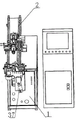
FIG. 1 is a schematic view of the combined structure of the bending mechanism and the automatic sample feeding mechanism of the present invention;
fig. 2 is a schematic structural diagram of the bending mechanism of the present invention;
FIG. 3 is an enlarged view of a part of the structure of the clamping and moving mechanism of the present invention;
fig. 4 is a schematic view of a partial structure of the bending mechanism of the present invention;
the names and serial numbers of the parts in the figure are as follows:
1-workbench, 2-sample delivery track, 3-mounting seat a, 4-material ejecting positioning block, 5-mounting seat b, 6-rotating shaft a, 7-rotating seat, 8-chute a, 9-material ejecting block a, 10-material ejecting block b, 11-arc bracket a, 12-chute b, 13-arc bracket b, 14-arc bracket c, 15-moving sliding table, 16-clamping workbench, 17-mounting shell, 18-linear driving motor, 19-rotating driving motor, 20-rotating shaft b, 21-pushing cylinder, 22-sliding sleeve, 23-middle shaft, 24-guiding table, 25-wedge pushing block, 27-inclined plane, 28-transverse sliding rail, 29-one third arc ring, 30-screw rod, 31-rotary driving mechanism, 32-slide rod a, 33-connecting rod a, 34-connecting rod b, 35-cylinder mounting plate a, 36-cylinder a, 37-cylinder b, 38-connecting rod c, 39-connecting rod d, 40-slide rod b, 41-cylinder mounting plate b.
Detailed Description
The present invention will be described in detail with reference to the accompanying drawings and examples.
Example 1
As shown in fig. 1-4, the automatic tube bending device includes a workbench 1, a sample feeding track 2, a clamping moving mechanism, a rotation driving mechanism 31, a mounting seat a3, an ejection positioning block 4, a mounting seat b5, a rotation shaft a6, a rotation seat 7, a chute b12, a driving mechanism, an ejection block a9, and an ejection block b 10; the method is characterized in that:
the top surface of the workbench 1 is provided with a sample conveying track 2 which is horizontal along the front-back direction;
the mounting seats a3 and b5 are arranged on the front end of the workbench 1 in a left-right side-by-side manner; the mounting seat a3 is provided with a material ejecting positioning block 4, the right end face of the material ejecting positioning block 4 is provided with an arc-shaped groove a11 corresponding to the shape of a pipe, and the axial direction of the arc-shaped groove a11 is parallel to the direction of the sample conveying track 2;
the workbench 1 is provided with a rotary driving mechanism 31, the rotary shaft a6 is arranged on the front side of the mounting seat b5 through a shaft sleeve and is staggered with the position of the ejection positioning block 4, and the rotary driving mechanism 31 is connected with the rotary shaft a6 and drives the rotary shaft a6 to rotate; the rotating base 7 is arranged on the outer circular surface of the rotating shaft a6 and can rotate along with the rotating shaft a 6;
the top surface of the rotating seat 7 is provided with a horizontal sliding groove b12, the material ejecting block a9 is arranged in the sliding groove b12, and the driving mechanism is arranged on the rotating seat 7 and can drive the material ejecting block a9 to slide along the sliding groove b 12; the top end of the rotating shaft a6 is provided with a material ejecting block b10 opposite to the material ejecting block a9, and the opposite side surfaces of the material ejecting block a9 and the material ejecting block b10 are respectively provided with an arc-shaped groove b13 and an arc-shaped groove c14 which correspond to the shapes of the pipes; when the ejector block a9 rotates to the left limit position along with the rotating shaft a6, the sliding groove b12 is perpendicular to the axial direction of the arc-shaped groove a11, and the arc-shaped groove b13 is axially overlapped with the arc-shaped groove a 11;
the clamping moving mechanism is arranged on the sample feeding track 2 and used for clamping a pipe, the pipe is fed into the arc-shaped groove a11 of the ejection positioning block 4 and the arc-shaped groove c14 of the ejection block b10 when the pipe is located at the left limit position along the sample feeding track 2, and the driving mechanism pushes the ejection block a9 to enable the arc-shaped groove b13 and the arc-shaped groove c14 to form a clamping structure for the pipe.
The clamping and moving mechanism comprises a moving sliding table 15, a clamping workbench 16, an installation shell 17, a linear driving motor 18, a rotary driving motor 19, a rotary shaft b20, a pushing cylinder 21 and a sliding sleeve 22;
the movable sliding table 15 is arranged on the sample conveying track 2 through a sliding block, the clamping workbench 16 is arranged on the movable sliding table 15, and the mounting shell 17 is fixedly arranged at the rear part of the top surface of the clamping workbench 16; the rotating shaft b20 is mounted on the front side wall of the mounting shell 17 through a shaft sleeve, the front end extends horizontally forward, and the rear end extends into the mounting shell 17; the rotary driving motor 19 is arranged on the upper part of the front side wall of the mounting shell 17 and is positioned above the rotating shaft b20, the output shaft of the rotary driving motor 19 penetrates into the mounting shell 17, and the output shaft of the rotary driving motor 19 is connected with the rear end of the rotating shaft b20 through a transmission device and can drive the rotating shaft b20 to rotate;
the middle part of the front end face of the rotating shaft b20 is provided with a middle shaft 23 in the same axial direction, three groups of guide platforms 24 with a sector structure are arranged on the excircle surface of the middle shaft 23 at intervals along the circumferential direction, the opposite side surfaces of two adjacent guide platforms 24 are parallel to each other to form three guide grooves, and inclined wedge push blocks 25 are respectively arranged in the three guide grooves; the inner side surfaces of the inclined wedge push blocks 25 are respectively connected with the outer circular surface of the middle shaft 23 through return springs, and when the springs are in a natural state, the three inclined wedge push blocks 25 are pushed away and are far away from the middle shaft 23; the outer side surface of the inclined wedge pushing block 25 is an inclined surface 27, and the inclined surface 27 continuously expands outwards from back to front; the sliding sleeve 22 is sleeved on the rotating shaft b20, and the front end of the sliding sleeve 22 is sleeved on the rear ends of the three inclined wedge push blocks 25; the inner side surfaces of the three oblique wedge push blocks 25 are respectively provided with a third of circular arc rings 29;
the cylinder body of the pushing cylinder 21 is fixedly arranged on the left side surface or the right side surface of the mounting shell 17, the piston rod of the pushing cylinder 21 extends forwards horizontally and is hinged with the rear part of the sliding sleeve 22, the sliding sleeve 22 can be pushed to slide along the rotating shaft b20, and therefore the three inclined wedge push blocks 25 are pushed to fold, and at the moment, the three one-third circular arc rings 29 form a complete circular pipe groove to press the end of a pipe.
The automatic tube bending device further comprises a transverse slide rail 28, a transverse driving motor and a screw rod 30, wherein the top surface of the movable sliding table 15 is provided with the horizontal transverse slide rail 28, and the transverse slide rail 28 is perpendicular to the sample conveying rail 2; the clamping workbench 16 is arranged on a transverse sliding rail 28 through a sliding block, and the transverse driving motor is arranged on the clamping workbench 16 and is connected with the clamping workbench 16 through a screw rod 30 to drive the clamping workbench to move along the transverse sliding rail 28; the clamping table 16 is arranged on the top surface.
The rotation driving mechanism 31 is a servo motor and is connected with a rotation shaft a6 through gear engagement; the bottom surface of the front end of the workbench 1 is provided with a proximity switch aligned with the rotating shaft a6, the rotating shaft a6 is provided with a trigger block, and the trigger block is arranged on the outer circular surface of the rotating shaft a6 and is matched with the proximity switch to determine the zero point position. The proximity switch can be selected from the following types: yangming SP-05N.
A sliding groove a8 is formed in the top surface of the mounting seat a3, the jacking positioning block 4 is mounted in the sliding groove a8 through a sliding rod a32, and the lower end of the sliding rod a32 vertically penetrates downwards to penetrate out of the bottom surface of the mounting seat a 3;
the left side of the bottom surface of the mounting seat a3 is hinged with the upper end of a connecting rod a33, the lower end of a connecting rod a33 is hinged with the lower end of a connecting rod b34, and the upper end of the connecting rod b34 is hinged with the lower end of a sliding rod a 32;
the rear side surface of the mounting seat a3 is provided with a cylinder mounting plate a35, the lower part of the cylinder mounting plate a35 is vertically provided with a rotating shaft, and the tail end of the cylinder body of the cylinder a36 is mounted on the rotating shaft and can rotate relative to the rotating shaft; the piston rod of the cylinder a36 extends upwards to be hinged with the lower end of the connecting rod a33 or the connecting rod b 34.
The driving mechanism comprises a cylinder b37, a connecting rod c38 and a connecting rod d 39; the ejector block a9 is arranged in the sliding chute b12 through a sliding rod b40, and the lower end of the sliding rod b40 vertically penetrates downwards below the bottom surface of the rotating seat 7; the left side of the bottom surface of the rotating seat 7 is hinged with the upper end of a connecting rod c38, the lower end of a connecting rod c38 is hinged with the lower end of a connecting rod d39, and the upper end of a connecting rod d39 is hinged with the lower end of a sliding rod b 40; the front side and the rear side of the rotating seat 7 are provided with cylinder mounting plates b41, and the upper part of the cylinder body of the cylinder b37 is hinged and mounted at the lower end of the cylinder mounting plate b 41; the piston rod of the cylinder b37 extends upwards to be hinged with the lower end of the connecting rod c38 or the connecting rod d 39.
In the description of the present embodiment, the terms "upper", "lower", "left", "right", "front", "rear", and the like are used in the orientation or positional relationship shown in fig. 1 for convenience of description and simplicity of operation, but do not indicate or imply that the device or element referred to must have a particular orientation, be constructed in a particular orientation, and be operated, and therefore should not be construed as limiting the present invention.
Claims (6)
1. An automatic pipe bending device comprises a workbench (1), a sample conveying track (2), a clamping moving mechanism, a rotary driving mechanism (31), a mounting seat a (3), a material ejecting positioning block (4), a mounting seat b (5), a rotary shaft a (6), a rotary seat (7), a sliding groove b (12), a driving mechanism, a material ejecting block a (9) and a material ejecting block b (10); the method is characterized in that:
the top surface of the workbench (1) is provided with a sample conveying track (2) which is horizontal along the front-back direction;
the mounting seat a (3) and the mounting seat b (5) are arranged on the front end of the workbench (1) side by side along the left and right; the mounting seat a (3) is provided with a material ejecting positioning block (4), the right end face of the material ejecting positioning block (4) is provided with an arc-shaped groove a (11) corresponding to the shape of the pipe, and the axial direction of the arc-shaped groove a (11) is parallel to the direction of the sample conveying track (2);
the rotary driving mechanism (31) is arranged on the workbench (1), the rotary shaft a (6) is mounted on the front side of the mounting seat b (5) through a shaft sleeve and staggered with the ejection positioning block (4), and the rotary driving mechanism (31) is connected with the rotary shaft a (6) and drives the rotary shaft a (6) to rotate; the rotating seat (7) is arranged on the outer circular surface of the rotating shaft a (6) and can rotate along with the rotating shaft a (6);
a horizontal sliding groove b (12) is formed in the top surface of the rotating seat (7), the material ejecting block a (9) is installed in the sliding groove b (12), and the driving mechanism is arranged on the rotating seat (7) and can drive the material ejecting block a (9) to slide along the sliding groove b (12); the top end of the rotating shaft a (6) is provided with an ejection block b (10) relative to the ejection block a (9), and the opposite side surfaces of the ejection block a (9) and the ejection block b (10) are respectively provided with an arc-shaped groove b (13) and an arc-shaped groove c (14) corresponding to the shape of the pipe; when the material ejecting block a (9) rotates to a left limit position along with the rotating shaft a (6), the sliding groove b (12) is perpendicular to the axial direction of the arc-shaped groove a (11), and the arc-shaped groove b (13) is axially overlapped with the arc-shaped groove a (11);
the clamping moving mechanism is arranged on the sample conveying track (2) and used for clamping a pipe, the pipe is conveyed to the arc-shaped groove a (11) of the material ejecting positioning block (4) and the arc-shaped groove c (14) of the material ejecting block b (10) when the pipe is located at the left limit position along the sample conveying track (2), and the driving mechanism pushes the material ejecting block a (9) to enable the arc-shaped groove b (13) and the arc-shaped groove c (14) to form a clamping structure for the pipe.
2. The automatic pipe bending apparatus according to claim 1, wherein:
the clamping and moving mechanism comprises a moving sliding table (15), a clamping workbench (16), a mounting shell (17), a linear driving motor (18), a rotating driving motor (19), a rotating shaft b (20), a pushing cylinder (21) and a sliding sleeve (22);
the sample feeding device is characterized in that the movable sliding table (15) is arranged on the sample feeding track (2) through a sliding block, the clamping workbench (16) is arranged on the movable sliding table (15), and the mounting shell (17) is fixedly arranged at the rear part of the top surface of the clamping workbench (16); the rotating shaft b (20) is arranged on the front side wall of the mounting shell (17) through a shaft sleeve, the front end of the rotating shaft b horizontally extends forwards, and the rear end of the rotating shaft b extends into the mounting shell (17); the rotary driving motor (19) is arranged on the upper portion of the front side wall of the mounting shell (17) and is positioned above the rotary shaft b (20), an output shaft of the rotary driving motor (19) penetrates into the mounting shell (17), and the output shaft of the rotary driving motor (19) is connected with the rear end of the rotary shaft b (20) through a transmission device and can drive the rotary shaft b (20) to rotate;
the middle part of the front end face of the rotating shaft b (20) is provided with a middle shaft (23) in the same axial direction, three groups of guide platforms (24) with sector structures are arranged on the excircle surface of the middle shaft (23) at intervals along the circumferential direction of the middle shaft, the opposite side surfaces of two adjacent guide platforms (24) are mutually parallel to form three guide grooves, and inclined wedge push blocks (25) are respectively arranged in the three guide grooves; the inner side surfaces of the inclined wedge push blocks (25) are respectively connected with the excircle surface of the middle shaft (23) through return springs, and when the springs are in a natural state, the three inclined wedge push blocks (25) are pushed away and are far away from the middle shaft (23); the outer side surface of the inclined wedge pushing block (25) is an inclined surface (27), and the inclined surface (27) continuously expands outwards in the direction from back to front; the sliding sleeve (22) is sleeved on the rotating shaft b (20), and the front end of the sliding sleeve (22) is sleeved on the rear ends of the three inclined wedge push blocks (25); the inner side surfaces of the three oblique wedge push blocks (25) are respectively provided with one third of circular arc rings (29);
the cylinder body of the pushing cylinder (21) is fixedly arranged on the left side face or the right side face of the mounting shell (17), a piston rod of the pushing cylinder (21) horizontally extends forwards and is hinged with the rear portion of the sliding sleeve (22), the sliding sleeve (22) can be pushed to slide along the rotating shaft b (20), so that the three oblique wedge pushing blocks (25) are pushed to be folded, and at the moment, three one-third circular arc rings (29) form a complete circular pipe groove to compress the end of the pipe.
3. The automatic pipe bending apparatus according to claim 2, wherein:
the sample feeding device is characterized by further comprising a transverse sliding rail (28), a transverse driving motor and a screw rod (30), wherein the horizontal transverse sliding rail (28) is arranged on the top surface of the movable sliding table (15), and the transverse sliding rail (28) is perpendicular to the sample feeding track (2); the clamping workbench (16) is arranged on the transverse sliding rail (28) through a sliding block, and the transverse driving motor is arranged on the clamping workbench (16) and is connected with the clamping workbench through a screw rod (30) to drive the clamping workbench to move along the transverse sliding rail (28); the clamping worktable (16) is arranged on the top surface.
4. The automatic pipe bending apparatus according to claim 1, wherein: the rotation driving mechanism (31) is a servo motor and is connected with the rotating shaft a (6) through gear engagement; the bottom surface of the front end of the workbench (1) is provided with a proximity switch aligned with the rotating shaft a (6), the rotating shaft a (6) is provided with a trigger block, and the trigger block is arranged on the outer circular surface of the rotating shaft a (6) and is matched with the proximity switch to determine the zero point position.
5. The automatic pipe bending apparatus according to claim 1, wherein:
a sliding groove a (8) is formed in the top surface of the mounting seat a (3), the ejection positioning block (4) is mounted in the sliding groove a (8) through a sliding rod a (32), and the lower end of the sliding rod a (32) vertically penetrates downwards below the bottom surface of the mounting seat a (3);
the left side of the bottom surface of the mounting seat a (3) is hinged with the upper end of a connecting rod a (33), the lower end of the connecting rod a (33) is hinged with the lower end of a connecting rod b (34), and the upper end of the connecting rod b (34) is hinged with the lower end of a sliding rod a (32);
the rear side surface of the mounting seat a (3) is provided with a cylinder mounting plate a (35), the lower part of the cylinder mounting plate a (35) is vertically provided with a rotating shaft, and the tail end of a cylinder body of a cylinder a (36) is mounted on the rotating shaft and can rotate relative to the rotating shaft; the piston rod of the cylinder a (36) extends upwards to be hinged with the lower end of the connecting rod a (33) or the connecting rod b (34).
6. The automatic pipe bending apparatus according to claim 1, wherein:
the driving mechanism comprises a cylinder b (37), a connecting rod c (38) and a connecting rod d (39); the ejection block a (9) is arranged in the sliding chute b (12) through a sliding rod b (40), and the lower end of the sliding rod b (40) vertically penetrates downwards to penetrate below the bottom surface of the rotating seat (7); the left side of the bottom surface of the rotating seat (7) is hinged with the upper end of a connecting rod c (38), the lower end of the connecting rod c (38) is hinged with the lower end of a connecting rod d (39), and the upper end of the connecting rod d (39) is hinged with the lower end of a sliding rod b (40); the front side and the rear side of the rotating seat (7) are provided with cylinder mounting plates b (41), and the upper part of the cylinder body of the cylinder b (37) is hinged and mounted at the lower end of the cylinder mounting plate b (41); the piston rod of the cylinder b (37) extends upwards to be hinged with the lower end of the connecting rod c (38) or the connecting rod d (39).
Priority Applications (1)
| Application Number | Priority Date | Filing Date | Title |
|---|---|---|---|
| CN202023209905.XU CN214556486U (en) | 2021-08-27 | 2021-08-27 | Automatic pipe bending device |
Applications Claiming Priority (1)
| Application Number | Priority Date | Filing Date | Title |
|---|---|---|---|
| CN202023209905.XU CN214556486U (en) | 2021-08-27 | 2021-08-27 | Automatic pipe bending device |
Publications (1)
| Publication Number | Publication Date |
|---|---|
| CN214556486U true CN214556486U (en) | 2021-11-02 |
Family
ID=78365813
Family Applications (1)
| Application Number | Title | Priority Date | Filing Date |
|---|---|---|---|
| CN202023209905.XU Active CN214556486U (en) | 2021-08-27 | 2021-08-27 | Automatic pipe bending device |
Country Status (1)
| Country | Link |
|---|---|
| CN (1) | CN214556486U (en) |
Cited By (1)
| Publication number | Priority date | Publication date | Assignee | Title |
|---|---|---|---|---|
| CN116871369A (en) * | 2023-07-10 | 2023-10-13 | 广东大洋医疗科技股份有限公司 | Bending equipment and bending process for through pipe |
-
2021
- 2021-08-27 CN CN202023209905.XU patent/CN214556486U/en active Active
Cited By (1)
| Publication number | Priority date | Publication date | Assignee | Title |
|---|---|---|---|---|
| CN116871369A (en) * | 2023-07-10 | 2023-10-13 | 广东大洋医疗科技股份有限公司 | Bending equipment and bending process for through pipe |
Similar Documents
| Publication | Publication Date | Title |
|---|---|---|
| CN107716766B (en) | Automatic pipe turning and feeding device of pipe bending machine and application method of automatic pipe turning and feeding device | |
| CN214556486U (en) | Automatic pipe bending device | |
| CN107716758B (en) | Flexible feeding device of pipe bending machine and pipe bending machine thereof | |
| CN111865010A (en) | Full-automatic production line and production process for rotor finish machining | |
| CN111389988B (en) | Rolling bulging device for metal round tube | |
| CN115446294A (en) | A mould for producing automobile wheel hub | |
| CN108906952B (en) | Seamless steel pipe hot-pressing integral forming high-speed wire spool body machine and use method thereof | |
| CN112642892B (en) | Automatic pipe bending equipment | |
| CN109550826A (en) | Automatic spinning machine | |
| CN106862877B (en) | Welding and riveting equipment for automobile brake bottom plate | |
| CN112642895B (en) | Automatic production line for bent pipes | |
| CN110091207B (en) | Double-end chamfering machine capable of continuously and simultaneously machining multiple pipe fittings and feeding mechanism thereof | |
| CN115193993B (en) | Tubular workpiece machining equipment and machining method thereof | |
| CN116871369A (en) | Bending equipment and bending process for through pipe | |
| CN110560524A (en) | Multi-radius pipe bender | |
| CN212543603U (en) | Full-automatic production line for finish machining of rotor | |
| CN114603365A (en) | Part machining device of carrier and technological method thereof | |
| CN211539253U (en) | Automatic double-necking machine for low-hardness copper pipe | |
| CN212384467U (en) | Split type straightening machine that cuts off | |
| CN210995941U (en) | Multi-radius pipe bending machine | |
| CN209452589U (en) | Automatic spinning machine | |
| CN113976753A (en) | Full-automatic pipe contracting equipment | |
| CN111844335A (en) | Bamboo pen container continuous production equipment | |
| CN109158481B (en) | Automatic change well system of contracting | |
| CN212944798U (en) | Air pipe joint pressure switch bending machine |
Legal Events
| Date | Code | Title | Description |
|---|---|---|---|
| GR01 | Patent grant | ||
| GR01 | Patent grant |