CN214553743U - Blood specimen test-tube rack with rock function - Google Patents
Blood specimen test-tube rack with rock function Download PDFInfo
- Publication number
- CN214553743U CN214553743U CN202022325581.XU CN202022325581U CN214553743U CN 214553743 U CN214553743 U CN 214553743U CN 202022325581 U CN202022325581 U CN 202022325581U CN 214553743 U CN214553743 U CN 214553743U
- Authority
- CN
- China
- Prior art keywords
- test tube
- rack
- base
- test
- rocks
- Prior art date
- Legal status (The legal status is an assumption and is not a legal conclusion. Google has not performed a legal analysis and makes no representation as to the accuracy of the status listed.)
- Active
Links
Images


Landscapes
- Automatic Analysis And Handling Materials Therefor (AREA)
Abstract
The utility model belongs to the technical field of medical instrument, concretely relates to blood sample test-tube rack with sway function, which comprises a base, the left and right sides of the base are symmetrically provided with supporting vertical plates respectively, the upper middle positions of the two supporting vertical plates are provided with a rotating shaft, a test tube sway rack is fixed on the rotating shaft, a plurality of groups of test tube clamping holes with different specifications are uniformly arranged on the test tube sway rack, and a test tube fixing device is arranged on each test tube clamping hole; one side that the arbitrary one end of pivot passed the support riser is equipped with the device that rocks, and the meshing of rocking device through rack and gear turns into the rotary motion of pivot with the reciprocal linear motion of rack along the lead screw, and then drives the test tube and rocks a reciprocating rotation. The utility model discloses simple structure, reasonable in design can regularly rock the test tube and rock the frame, ensures that same batch of blood sample evenly rocks, has obviously improved and has rocked efficiency, has reduced medical personnel's work load, and is fixed firm by the test tube that rocks, guarantees that the test tube rocks the security of in-process.
Description
Technical Field
The utility model belongs to the technical field of medical instrument, concretely relates to blood sample test-tube rack with rock function.
Background
The test tube rack is the most basic laboratory instrument in a chemical laboratory for placing (sometimes, test tubes can be placed on the test tube rack to observe the phenomenon of a certain experiment) and drying the test tubes. The test tube rack is attached with a corresponding number of small wooden columns and small holes. The foraminous tube may be placed upright for use or to allow continued observation of the reaction. The cleaned test tube with the column can be placed upside down for air drying.
In clinical medicine, in order to research the etiology, diagnosis, treatment and prevention of diseases, the level of clinical treatment is improved, and the science of promoting human health generally needs to extract blood samples of patients for inspection, a plurality of inspection items exist, and the blood cannot be solidified, in the blood extraction process, some blood samples need to dissolve blood with anticoagulant inside a test tube, so after the blood samples are extracted, the test tube needs to be shaken leftwards and rightwards continuously to achieve dissolving, but the existing shaking mode is generally manual shaking, irregular shaking and uneven, the test tube is easy to fall off, the test tube is smashed, and the hands of medical staff feel tired after long-time shaking, and inconvenience is brought to work.
In view of the above, the present inventors have devised a blood specimen tube rack with a shaking function to solve the above technical problems.
SUMMERY OF THE UTILITY MODEL
In order to solve the above-mentioned problem that exists among the prior art, the utility model aims to provide a blood sample test-tube rack with rock function to solve and save the blood sample of gathering among the prior art in the test tube, need medical personnel to rock the test tube manually and waste time and energy inefficiency, the test tube easily drops, rocks inhomogeneous problem.
The to-be-solved technical problem of the utility model is realized through following technical scheme: the test tube shaking frame is fixedly connected with a test tube shaking frame, a plurality of groups of test tube clamping holes with different specifications are uniformly arranged on the test tube shaking frame, and each test tube clamping hole is provided with a test tube fixing device;
any end of the first rotating shaft penetrates through one side of the supporting vertical plate, two identical telescopic rods which are vertically downward are fixedly arranged at intervals, and a second rotating shaft is arranged between the bottom ends of the two telescopic rods;
the base upper end is installed and is rocked the device, rock the device including fixed setting up at the epaxial gear of second pivot and vertically set up both ends around the base, and be located the fixed bolster of gear below, two swing joint has the silk between the fixed bolster, the end connection driving motor of lead screw, driving motor's output shaft passes through the coupling joint with the lead screw, be provided with screw nut on the lead screw, the fixed rack that is provided with in screw nut upper end, rack and gear engagement.
Further, test tube fixing device includes first arc splint and second arc splint, spring coupling is passed through with the both sides of second arc splint to first arc splint, second arc splint are fixed on the test tube rocks the frame, second arc splint motion can be kept away from to first arc splint for press from both sides tightly or loosen the test tube.
Further, the both sides of first arc splint are equipped with the fixing base respectively, the spring mounting is on the fixing base, the test tube rocks and is fixed with the guide rail on the frame, the free end of guide rail passes the fixing base, convex surface one side of first arc splint is provided with the pull rod, the pull rod end stretches out the test tube and rocks the frame and rocks the outside handle fixed connection of frame with the setting at the test tube.
Furthermore, flexible buffer pads are installed on the two sides of the first arc-shaped clamping plate and the second arc-shaped clamping plate.
Further, rubber gaskets are paved on the inner surfaces of the first arc-shaped clamping plate and the second arc-shaped clamping plate.
Further, the gear is a half gear, and the gear is located right above the rack.
Further, two still fixed test tube rack that is provided with between the support riser, the hole is placed to the test tube of seting up a plurality of different specifications on the test tube rack, be provided with on the base and place the hemispherical groove that the hole corresponds with every test tube, laid the sponge in the hemispherical groove, the test tube rack is located the test tube and rocks the below of frame, and keep away from the test tube and rock the frame.
Further, evenly install a plurality of lugs that are used for the reverse plug to place the test tube on the base, every the lug sets up in the place ahead that supports the riser.
Furthermore, the bottom end of each convex column is provided with a circle of drainage grooves, and each drainage groove is communicated with a drainage ditch arranged on the base.
Furthermore, a plug is arranged at the water outlet end of the drainage ditch.
Compared with the prior art, the beneficial effects of the utility model are that:
1. the utility model relates to a blood sample test-tube rack with sway function, test tube sway rack can set up the test tube clamping hole of different specifications according to daily test tube frequency of use, is provided with test tube fixing device on each test tube clamping hole, prevents that the test tube from dropping, expands application range; the test tube rocks the pivot respectively that puts up through both ends the activity set up on the support riser of both sides, the arbitrary one end of pivot is passed and is supported riser one side and be provided with rocking device, utilize the lead screw nut reciprocating motion characteristic on the motor just reverse drive lead screw, reunion gear and rack transmission principle, turn into the rotary motion of pivot with the reciprocal linear motion of rack, and then drive the test tube and rock the regular reciprocating rotation of frame, thereby the realization is to fixing evenly rocking the blood sample on the test tube rocks the frame, the improvement rocks efficiency, time saving and labor saving.
2. The utility model relates to a blood sample test-tube rack with rock function breaks away from the test-tube rack in order to prevent that the test tube from rocking the in-process, this novel design test tube fixing device, can press from both sides the tight fixed of clamp to the test tube of every different specifications, and test tube fixing device adopts spring buffering fixed knot to construct, can self-adaptation press from both sides tight degree, prevents to press from both sides broken test tube.
3. The utility model relates to a blood sample test-tube rack with rock function, it rocks the gear in the device and adopts half gear, through half gear and rack toothing transmission, realizes that the test tube rocks the frame and reciprocates at 180 degrees within ranges and rotates, prevents to rotate the blood sample in the test tube by a wide margin and flows from the test tube mouth.
4. The utility model relates to a blood sample test-tube rack with rock function evenly installs a plurality of projections that are used for inserting the placing test tube upside down on the base, and is provided with round drainage groove in the bottom of every projection, and drainage groove is linked together with the escape canal, and the drainage exit end is provided with the end cap. Through above-mentioned design, when the accuse does the test tube, can effectively solve the water in the test tube and flow to table surface along the test-tube rack on, keep the mesa clean.
Drawings
Fig. 1 is a schematic view of the overall structure of a blood specimen tube rack with shaking function according to the present invention;
fig. 2 is a front view of a blood specimen tube rack with shaking function according to the present invention;
fig. 3 is a left side view of a blood specimen tube rack with shaking function according to the present invention;
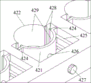
FIG. 4 is a schematic view of the structure of the test tube shaking frame of the present invention;
FIG. 5 is an enlarged view of portion A of FIG. 4;
FIG. 6 is a top view of the test tube shaking frame of the present invention;
fig. 7 is an enlarged sectional view of B-B in fig. 6.
In the figure: 1. a base; 2. supporting a vertical plate; 3. a first rotating shaft; 4. shaking the test tube; 5. a telescopic rod; 6. a second rotating shaft; 7. a shaking device; 8. placing a test tube rack; 9. a convex column; 11. A hemispherical recess; 12. a drainage groove; 13. a drainage ditch; 14. a plug; 21. a through hole; 22. a first bearing; 41. a test tube clamping hole; 42. a test tube fixing device; 51. A fastener; 52. a movable member; 61. a second bearing; 71. a gear; 72. fixing a bracket; 73. a lead screw; 74. a drive motor; 75. a coupling; 76. a lead screw nut; 77. a rack; 81. test tube placement holes; 111. a sponge; 421. a first arc splint; 422. a second arc-shaped splint; 423. a spring; 424. a fixed seat; 425. a guide rail; 426. a pull rod; 427. a handle; 428. a flexible cushion; 429. a rubber gasket.
Detailed Description
In order to make the objects, technical solutions and advantages of the present invention more apparent, the present invention will be described below with reference to specific embodiments shown in the accompanying drawings. It is to be understood that such description is merely illustrative and not restrictive of the scope of the invention. Moreover, in the following description, descriptions of well-known structures and techniques are omitted so as to not unnecessarily obscure the concepts of the present invention.
In the description of the present invention, it is to be understood that the terms "center", "longitudinal", "lateral", "length", "width", "thickness", "upper", "lower", "front", "rear", "left", "right", "vertical", "horizontal", "top", "bottom", "inner", "outer", "clockwise", "counterclockwise", and the like indicate orientations or positional relationships based on the orientations or positional relationships shown in the drawings, and are only for convenience of description and to simplify the description, but do not indicate or imply that the device or element referred to must have a particular orientation, be constructed and operated in a particular orientation, and therefore should not be construed as limiting the present invention.
Example (b): referring to fig. 1 ~ 7, a blood sample test-tube rack with rock function, including base 1, the symmetry is provided with respectively in the 1 upper end left and right sides of base and supports riser 2, through-hole 21 has been seted up respectively to two top intermediate positions that support riser 2, be provided with first pivot 3 in two through- holes 21, 3 both ends of first pivot cooperate with the first bearing 22 that sets up in passing through 2 respectively, fixedly connected with test tube rocks frame 4 on the first pivot 3, the test tube rocks the test tube and evenly is equipped with the test tube clamping hole 41 of the different specifications of multiunit on the frame 4, test tube clamping hole 41 can be seted up according to the specification of daily use test tube, be provided with test tube fixing device 42 on every test tube clamping hole 41, in order to prevent that the test tube from dropping. Pass one side below of supporting riser 2 at 3 arbitrary one ends of first pivot and set up rocking device 7, rock frame 4 through rocking device 7 drive test tube and rotate to replace medical personnel's manual rocking, use manpower sparingly, improve and rock efficiency.
Specifically, as shown in fig. 1 to 3, two identical telescopic rods 5 which are vertically downward are fixedly arranged at intervals at any end of a first rotating shaft 3 which penetrates through one side of a supporting vertical plate 2, each telescopic rod 5 is composed of a fastening piece 51 at the upper end and a moving piece 52 which is sleeved in the fastening piece 51, a second rotating shaft 6 is arranged between the bottom ends of the two telescopic rods 5, and the second rotating shaft 6 is matched with a second bearing 61 which is arranged on each telescopic rod 5; the shaking device 7 is positioned below the second bearing 61 and is installed at the upper end of the base 1, the shaking device 7 comprises a gear 71 fixedly arranged on the second rotating shaft 6 and fixing brackets 72 longitudinally arranged at the front end and the rear end of the base 1 and positioned below the gear 71, a lead screw 73 is movably connected between the two fixing brackets 72, the end part of the lead screw 73 is connected with a driving motor 74, preferably, the driving motor 74 is a servo motor, the output shaft of the driving motor 74 is connected with the lead screw 73 through a coupler 75, a lead screw nut 76 is arranged on the lead screw 73, a rack 77 is fixedly arranged at the upper end of the lead screw nut 76, the rack 77 is positioned right below the gear 71, and the rack 77 is meshed with the gear 71,
through the aforesaid setting back, the positive and negative rotation of control driving motor 74, the rack 77 that the drive was fixed on screw nut is along the reciprocal linear motion of lead screw 73, combines rack and pinion transmission principle again, can drive telescopic link 5 and be rotary motion around the center of first pivot 3, and then makes the test tube rock the regular reciprocating rotation of frame 4 to the realization is evenly rocked the blood sample of fixing on the test tube rock frame 4, improves and rocks efficiency.
Preferably, gear 71 is the half-gear, and gear 71 is located rack 77 directly over, the number of teeth of rack 77 and the number of teeth phase-match of half-gear, make rack 77 unidirectional movement once, gear 71 unidirectional rotation 180 degrees, once when rack 77 reciprocating motion, then gear 71 reciprocating rotation 180 degrees to regular rocking the test tube rocks frame 4, guarantee that blood sample evenly rocks, select the half-gear in addition to avoid the test tube to rock frame 4 and swing by a wide margin, prevent that the blood sample in the test tube from flowing out from the test tube mouth.
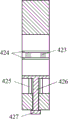
As shown in fig. 4-7, the utility model discloses test tube fixing device 42 includes first arc splint 421 and second arc splint 422, first arc splint 421 is connected through spring 423 with second arc splint 422's both sides, second arc splint 422 fixes on the test tube rocks frame 4, second arc splint 422 motion can be kept away from to first arc splint 421 under the exogenic action, the adjustable through-hole that first arc splint 421 and second arc splint 422 formed promptly, under spring 66 is in natural state, the diameter of adjustable through-hole is generally less than the circular through-hole diameter 0.5-2mm that corresponds, so that the test tube is in and presss from both sides tight fixed state, when the test tube is taken off to needs, only need stimulate first arc splint 421, it is preferred, rubber packing ring 429 is all laid at two splint curved internal surfaces, the test tube that weares and teares when preventing to press from both sides tight.
Wherein, the both sides of first arc splint 421 are equipped with fixing base 424 respectively, spring 423 installs on fixing base 424 and correspond position elastic connection in second arc splint 422, the test tube rocks and is fixed with guide rail 425 on the frame 4, the free end of guide rail 425 passes fixing base 424, guide rail 425 can set up the multiunit according to the thickness of arc splint with spring 423, the symmetric distribution is on arc splint both sides fixing base, convex surface one side of first arc splint 421 is provided with draws 426, the pull rod 426 end stretches out the test tube and rocks frame 4 and with the setting at the test tube and rock the outside handle 427 fixed connection of frame 4, handle 427 is preferably flat cylinder, handle 427 excircle profile is provided with anti-skidding line.
Through the arrangement, when a test tube needs to be shaken, the first arc-shaped clamping plate 421 is far away from the second arc-shaped clamping plate 422 along the guide rails 425 on two sides by pulling the pull handle 427, so that the hole distance formed by the two arc-shaped clamping plates is enlarged, the test tube can conveniently stretch into the test tube, after the test tube is placed, the pull handle 427 is slowly loosened, and the first arc-shaped clamping plate 421 and the second arc-shaped clamping plate 422 clamp the test tube under the action of the spring 423; in order to prevent misoperation, vertical flexible buffer cushions 428 are preferably arranged on two sides of the first arc-shaped clamping plate 421 and the second arc-shaped clamping plate 422 or the fixing seat 424, the flexible buffer cushions 428 are made of elastic soft materials and adopt spring buffer structures, the degree of self-adaptive clamping can be achieved, the test tube is prevented from being broken, and after the test tube is fixed, the shaking device is started, so that the blood sample can be shaken.
The utility model discloses still fixed test tube rack 8 that is provided with between two support risers 2, test tube rack 8 can prevent some test tubes that need not rock, the hole 81 is placed to the test tube of seting up a plurality of different specifications on test tube rack 8, so as to place the test tube of different specifications, be provided with on the base 1 and place the hemispherical recess 11 that hole 81 corresponds with every test tube, the screens when hemispherical recess 11 is used for the test tube to normally place, the one deck 2-4mm sponge is laid to preferred in hemispherical recess 11, be used for protecting the test tube, wherein test tube rack 8 is located the test tube and rocks the below of frame 4, and keep away from the test tube and rock frame 4, prevent that the test tube from rocking the use that influences test tube rack 8 when frame 4 rocks.
Preferably, as shown in fig. 1, a plurality of convex columns 9 for placing the test tubes in an inverted manner are uniformly installed on the base 1, each convex column 9 is arranged in front of the supporting vertical plate 2 and is away from the supporting vertical plate 2 by a certain distance, preferably, the convex column 9 is a cylindrical table body, the diameter of the bottom of the cylindrical table body is larger than that of the top of the cylindrical table body, so that the test tubes can be stably dried; the surface of the convex column 9, which is contacted with the base 1, is provided with a circle of drainage grooves 12, the drainage grooves 12 are communicated with drainage ditches 13 arranged on one side of the base 1, and the water outlet ends of the drainage ditches 13 are provided with plugs 14, so that when the test tube is inversely inserted on the convex column 9 to be dried, water drops can fall into the drainage grooves 12 and are finally discharged through the drainage ditches 13. Through above-mentioned design, when the accuse does the test tube, can effectively solve the water in the test tube and flow to table surface along the test-tube rack on, keep the mesa clean.
The foregoing is a more detailed description of the present invention, taken in conjunction with the specific preferred embodiments thereof, and it is not intended that the invention be limited to the specific embodiments shown and described. To the utility model belongs to the technical field of ordinary technical personnel, do not deviate from the utility model discloses under the prerequisite of design, can also make a plurality of simple deductions or replacement, all should regard as belonging to the utility model discloses a protection scope.
Claims (10)
1. The utility model provides a blood sample test-tube rack with shake function which characterized in that: the test tube shaking device comprises a base (1), wherein supporting vertical plates (2) are symmetrically arranged on the left side and the right side of the upper end of the base (1) respectively, through holes (21) are formed in the middle positions above the two supporting vertical plates (2) respectively, first rotating shafts (3) are arranged in the two through holes (21), test tube shaking frames (4) are fixedly connected onto the first rotating shafts (3), a plurality of groups of test tube clamping holes (41) with different specifications are uniformly formed in each test tube shaking frame (4), and a test tube fixing device (42) is arranged on each test tube clamping hole (41);
any end of the first rotating shaft (3) penetrates through one side of the supporting vertical plate (2) and is fixedly provided with two identical vertical downward telescopic rods (5) at intervals, and a second rotating shaft (6) is arranged between the bottom ends of the two telescopic rods (5);
base (1) upper end is installed and is rocked device (7), rock device (7) including fixed gear (71) that sets up on second pivot (6) with vertically set up both ends around base (1), and be located fixed bolster (72) of gear (71) below, two swing joint has lead screw (73) between fixed bolster (72), the end connection driving motor (74) of lead screw (73), the output shaft of driving motor (74) is connected through shaft coupling (75) with lead screw (73), be provided with screw nut (76) on lead screw (73), fixed rack (77) that is provided with in screw nut (76) upper end, rack (77) and gear (71) meshing.
2. The blood specimen tube rack with shaking function according to claim 1, characterized in that: test tube fixing device (42) include first arc splint (421) and second arc splint (422), first arc splint (421) are passed through spring (423) with the both sides of second arc splint (422) and are connected, second arc splint (422) are fixed on test tube rocks frame (4), second arc splint (422) motion can be kept away from in first arc splint (421) for press from both sides tightly or loosen the test tube.
3. The blood specimen tube rack with shaking function according to claim 2, characterized in that: the both sides of first arc splint (421) are equipped with fixing base (424) respectively, install on fixing base (424) spring (423), the test tube rocks and is fixed with guide rail (425) on frame (4), the free end of guide rail (425) passes fixing base (424), the convex surface one side of first arc splint (421) is provided with pull rod (426), pull rod (426) end stretch out the test tube and rock frame (4) outside handle (427) fixed connection at the test tube with the setting.
4. The blood specimen tube rack with shaking function according to claim 2, characterized in that: and flexible buffer cushions (428) are arranged on two sides of the first arc-shaped clamping plate (421) and the second arc-shaped clamping plate (422).
5. The blood specimen tube rack with shaking function according to claim 2, characterized in that: and rubber gaskets (429) are paved on the inner surfaces of the first arc-shaped clamping plate (421) and the second arc-shaped clamping plate (422).
6. The blood specimen tube rack with shaking function according to claim 1, characterized in that: the gear (71) is a half gear, and the gear (71) is positioned right above the rack (77).
7. The blood specimen tube rack with shaking function according to claim 1, characterized in that: two still fixed test tube rack (8) that are provided with between support riser (2), set up the test tube of a plurality of different specifications on test tube rack (8) and place hole (81), be provided with on base (1) and place hemispherical groove (11) that hole (81) correspond with every test tube, sponge (111) have been laid in hemispherical groove (11), test tube rack (8) are located the test tube and rock the below of frame (4), and keep away from the test tube and rock frame (4).
8. The blood specimen tube rack with shaking function according to claim 1, characterized in that: a plurality of convex columns (9) used for inversely inserting and placing test tubes are evenly arranged on the base (1), and each convex column (9) is arranged in front of the supporting vertical plate (2).
9. The blood specimen tube rack with shaking function according to claim 8, wherein: the bottom end of each convex column (9) is provided with a circle of drainage grooves (12), and each drainage groove (12) is communicated with a drainage ditch (13) arranged on the base (1).
10. The blood specimen tube rack with shaking function according to claim 9, wherein: and a plug (14) is arranged at the water outlet end of the drainage ditch (13).
Priority Applications (1)
| Application Number | Priority Date | Filing Date | Title |
|---|---|---|---|
| CN202022325581.XU CN214553743U (en) | 2020-10-19 | 2020-10-19 | Blood specimen test-tube rack with rock function |
Applications Claiming Priority (1)
| Application Number | Priority Date | Filing Date | Title |
|---|---|---|---|
| CN202022325581.XU CN214553743U (en) | 2020-10-19 | 2020-10-19 | Blood specimen test-tube rack with rock function |
Publications (1)
| Publication Number | Publication Date |
|---|---|
| CN214553743U true CN214553743U (en) | 2021-11-02 |
Family
ID=78313105
Family Applications (1)
| Application Number | Title | Priority Date | Filing Date |
|---|---|---|---|
| CN202022325581.XU Active CN214553743U (en) | 2020-10-19 | 2020-10-19 | Blood specimen test-tube rack with rock function |
Country Status (1)
| Country | Link |
|---|---|
| CN (1) | CN214553743U (en) |
Cited By (4)
| Publication number | Priority date | Publication date | Assignee | Title |
|---|---|---|---|---|
| CN114432954A (en) * | 2022-01-25 | 2022-05-06 | 王水琴 | Even equipment of shaking is used in detection of hematology branch of academic or vocational study vein blood sample |
| CN114950211A (en) * | 2022-06-22 | 2022-08-30 | 韦爱珍 | Test tube shaking device |
| CN115445489A (en) * | 2022-08-10 | 2022-12-09 | 武汉大学 | Heparin tube mixing appearance |
| CN116474856A (en) * | 2023-05-11 | 2023-07-25 | 首都医科大学 | Test tube rack with oscillation function |
-
2020
- 2020-10-19 CN CN202022325581.XU patent/CN214553743U/en active Active
Cited By (7)
| Publication number | Priority date | Publication date | Assignee | Title |
|---|---|---|---|---|
| CN114432954A (en) * | 2022-01-25 | 2022-05-06 | 王水琴 | Even equipment of shaking is used in detection of hematology branch of academic or vocational study vein blood sample |
| CN114432954B (en) * | 2022-01-25 | 2024-07-02 | 南京锐之青信息科技有限公司 | Shaking equipment for detecting blood sample of blood department vein |
| CN114950211A (en) * | 2022-06-22 | 2022-08-30 | 韦爱珍 | Test tube shaking device |
| CN114950211B (en) * | 2022-06-22 | 2024-08-13 | 韦爱珍 | Test tube shaking device |
| CN115445489A (en) * | 2022-08-10 | 2022-12-09 | 武汉大学 | Heparin tube mixing appearance |
| CN116474856A (en) * | 2023-05-11 | 2023-07-25 | 首都医科大学 | Test tube rack with oscillation function |
| CN116474856B (en) * | 2023-05-11 | 2024-03-08 | 首都医科大学 | Test tube rack with oscillation function |
Similar Documents
| Publication | Publication Date | Title |
|---|---|---|
| CN214553743U (en) | Blood specimen test-tube rack with rock function | |
| CN107737624A (en) | A kind of medical paediatrics woven hose quick crashing equipment | |
| CN209662262U (en) | A kind of anaesthetic apparatus chlorination equipment | |
| CN214970195U (en) | Transfusion bracket for outpatient department nursing | |
| CN205307303U (en) | High -efficient automatically cleaning frame of orthopedic surgery | |
| CN115517674A (en) | Blood drawing device convenient for fixing fingers | |
| CN211270750U (en) | Lumbar vertebrae hyperextension position support with adjustable | |
| CN208893035U (en) | A kind of nursing chlorination equipment | |
| CN208274698U (en) | A kind of gastroenterology inspection hospital bed | |
| CN209916477U (en) | Orthopedics nursing support holder | |
| CN209221140U (en) | A kind of gynecological and obstetrical nursing cleaning device | |
| CN213372605U (en) | Clinical infection-preventing cleaning and sterilizing device for orthopedics department | |
| CN214018596U (en) | Breathe internal medicine utensil disinfecting equipment | |
| CN109820672A (en) | A kind of Orthopedic Clinical dressing change device | |
| CN111134041A (en) | Electric pulse device for quadruped medical experiment | |
| CN218636280U (en) | Prevent pressing sore cleaning and disinfecting device of changing dressings | |
| CN213551636U (en) | Oral support device with replaceable sterilized tooth protection pad | |
| CN218682749U (en) | Oral care auxiliary device | |
| CN209074976U (en) | A kind of multi-function oral care cleaner | |
| CN213788593U (en) | A inspection device for anus enterochirurgia | |
| CN201168182Y (en) | Bed frame bracket of bottle for bathing eye | |
| CN214633120U (en) | Anesthesia apparatus degassing unit | |
| CN213098426U (en) | Belt cleaning device is used in nursing of severe medical science branch of academic or vocational study | |
| CN214174417U (en) | Observation device for clinical detection for diabetes | |
| CN210542281U (en) | Novel multifunctional reproductive center ovum-taking operating bed |
Legal Events
| Date | Code | Title | Description |
|---|---|---|---|
| GR01 | Patent grant | ||
| GR01 | Patent grant |