CN214550636U - Sterilizer for gynecological tumor - Google Patents
Sterilizer for gynecological tumor Download PDFInfo
- Publication number
- CN214550636U CN214550636U CN202022809694.7U CN202022809694U CN214550636U CN 214550636 U CN214550636 U CN 214550636U CN 202022809694 U CN202022809694 U CN 202022809694U CN 214550636 U CN214550636 U CN 214550636U
- Authority
- CN
- China
- Prior art keywords
- box
- sterilizer
- fixedly connected
- disinfection
- top end
- Prior art date
- Legal status (The legal status is an assumption and is not a legal conclusion. Google has not performed a legal analysis and makes no representation as to the accuracy of the status listed.)
- Active
Links
Images


Landscapes
- Apparatus For Disinfection Or Sterilisation (AREA)
Abstract
The utility model belongs to the field of medical machinery, in particular to a sterilizer for gynecological tumors, which comprises a sterilizer body, a box body, a supporting plate and an annular sleeve, wherein the top end of the sterilizer body is fixedly connected with the box body, the bottom end of the box body is fixedly connected with the supporting plate, the annular sleeve is fixedly connected in the middle of the top end of the box body, the left side of a spring is movably connected with an extrusion plate, the left side of the extrusion plate is fixedly connected with a telescopic block, the left side of the top end of the sterilizer body is movably connected with a cap, the sterilizer can be opened by the cap, when medical personnel need to sterilize patients, only one hand is needed to hold a hose, then a spray head is aligned to the place needing sterilization, finally the other hand is used for twisting a valve anticlockwise, spray pipes on the spray head are uniformly distributed, sprayed disinfectant is uniformly distributed, water pressure can not hurt the patients, after the patients are sterilized, the cap can be opened, then the sterilizer can be cleaned and the poison water can be removed, the problem that the user needs to take the bottle when the bottle needs to be disinfected is avoided.
Description
Technical Field
The utility model belongs to the field of medical equipment, specifically a sterilizer for gynecological tumor.
Background
The tumor is a new organism formed by local tissue cell proliferation under the action of various tumorigenic factors, the new organism is mostly in an occupied block-shaped protrusion, also called a neoplasm, and the tumor is divided into a benign tumor and a malignant tumor according to the cell characteristics of the new organism and the degree of harmfulness to the organism, and the disinfection process is indispensable and especially important in the treatment process of the tumor.
Present sterilizer that uses in oncology of hospital is mostly the snap-on subaerial, not only can not be convenient like this remove the sterilizer, long-time use can also be because the sterilizer contacts with ground for a long time, make the sterilizer wet, cause the sterilizer short circuit, use that can not be normal, current sterilizer function singleness, equipment once disinfects with high costs in addition, the operation is complicated, makes medical personnel use very inconvenient.
Therefore, how to design a sterilizer for gynecological tumors becomes a problem to be solved currently.
SUMMERY OF THE UTILITY MODEL
The utility model aims to provide a: in order to solve the problem that the sterilizer is easy to be affected with damp, the sterilizer for gynecological tumors is provided.
In order to achieve the above object, the utility model provides a following technical scheme:
a sterilizer for gynecological tumor, which comprises a sterilizer body, a box body, a supporting plate and an annular sleeve, the top end of the sterilizer is fixedly connected with a box body, the bottom end of the box body is fixedly connected with a supporting plate, the middle of the top end of the box body is fixedly connected with an annular sleeve, the middle of the annular sleeve is movably connected with a disinfection box, the top end of the box body is fixedly connected with a base, the right side of the annular sleeve is movably connected with a pull rod, the left side of the pull rod is movably connected with a spring, the left side of the spring is movably connected with an extrusion plate, the left side of the extrusion plate is fixedly connected with a telescopic block, the left side of the top end of the disinfection box is movably connected with a cover cap, the right side of the top end of the sterilizing box is movably connected with a valve, the top end of the sterilizing box is fixedly connected with a hose, the left side fixedly connected with shower nozzle of hose, the bottom swing joint of backup pad has the pulley.
Preferably, the front surface of the box body is fixedly connected with a push rod.
Preferably, the middle of the box body is fixedly connected with a disinfection pad.
Preferably, the top end of the base is fixedly connected with a disinfection lamp.
Preferably, the box body and the annular sleeve in the middle of the top end of the box body, the pull rod on the right side of the annular sleeve, the spring on the left side of the pull rod, the extrusion plate on the left side of the spring and the telescopic block on the left side of the extrusion plate form a cleaning structure together.
Preferably, the annular sleeve is composed of a disinfection box in the middle of the annular sleeve, a cover cap on the left side of the top end of the disinfection box, a valve on the right side of the top end of the disinfection box, a hose on the top end of the disinfection box and a spray head on the left side of the hose.
Compared with the prior art, the beneficial effects of the utility model are that:
1. the utility model discloses in, can fix the disinfect box and also can take off at any time on the sterilizer, when the disinfect box need take off, medical personnel only need stimulate the pull rod, and the stripper plate of connecting the pull rod will extrude the spring, and the flexible piece of the inside also can be driven and outwards removed during the extrusion, and the disinfect box just can be taken out at this moment, has avoided the problem that the disinfect box dropped easily.
2. The utility model discloses in, when medical personnel need disinfect for patient, only need a hand to hold the hose, then aim at the place that needs the disinfection with the shower nozzle, the valve is moved to last another anticlockwise twist of hand, the spray tube on the shower nozzle is evenly distributed, the antiseptic solution that sprays out is evenly distributed, and water pressure can not injure patient, after disinfecting for patient and accomplishing, can open the block then rinse the disinfect box and remove the poison water again, the problem of getting still will getting of removing the dress when having avoided needing the disinfection.
Drawings
Fig. 1 is a schematic diagram of the whole vertical structure of the present invention.
Fig. 2 is a schematic diagram of the structure of the annular sleeve of the present invention.
Fig. 3 is a schematic diagram of the structure of the disinfection box of the present invention.
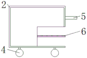
Fig. 4 is a schematic diagram of the overall cross-sectional structure of the present invention.
In the figure: 1. the sterilizer is integrated; 2. a box body; 3. a support plate; 4. a pulley; 5. a push rod; 6. a disinfection pad; 7. an annular sleeve; 8. a sterilizing box; 9. a base; 10. a sterilizing lamp; 701. a pull rod; 702. a spring; 703. a pressing plate; 704. a telescopic block; 801. capping; 802. a valve; 803. a hose; 804. and (4) a spray head.
Detailed Description
The technical solution in the embodiments of the present invention will be clearly and completely described below with reference to the drawings in the embodiments of the present invention, and it is obvious that the described embodiments are only some embodiments of the present invention, rather than all embodiments, and all other embodiments obtained by a person of ordinary skill in the art without creative work belong to the protection scope of the present invention based on the embodiments of the present invention.
In a first embodiment, please refer to fig. 1-4, the present invention provides a technical solution: a sterilizer for gynecological tumor, which comprises a sterilizer body 1 and a box body 2, backup pad 3 and annular cover 7, the whole 1 top fixedly connected with box 2 of sterilizer, the bottom fixedly connected with backup pad 3 of box 2, fixedly connected with annular cover 7 in the middle of the top of box 2, the middle swing joint of annular cover 7 has disinfect box 8, the top fixedly connected with base 9 of box 2, the right side swing joint of annular cover 7 has pull rod 701, the left side swing joint of pull rod 701 has spring 702, the left side swing joint of spring 702 has stripper plate 703, the left side fixedly connected with flexible piece 704 of stripper plate 703, the top left side swing joint of disinfect box 8 has block 801, the top right side swing joint of disinfect box 8 has valve 802, the top fixedly connected with hose 803 of disinfect box 8, the left side fixedly connected with shower nozzle 804 of hose 803, the bottom swing joint of backup pad 3 has pulley 4.
Preferably, the positive fixedly connected with push rod 5 of box 2, the effect of push rod 5 is used for promoting the sterilizer, when medical personnel disinfect for patient, the position of the different sterilizer in sterile place will be different, because the volume of sterilizer itself is great, medical personnel are difficult for moving, so be equipped with push rod 5, push rod 5 can cooperate pulley 4 to remove, can make medical personnel disinfect for the patient that different positions have the tumour, the problem that the sterilizer can not the adjusting position has been avoided.
Preferably, the middle fixedly connected with disinfection pad 6 of box 2, the effect of disinfection pad 6 is disinfected for the instrument in box 2, when medical personnel need disinfect for patient, need use multiple disinfection instrument, medical personnel can leave the instrument in the middle of box 2 on the cabinet board, disinfection instrument places the back in the air, probably the adhesion pollutant, lead to patient to receive the infection easily, so be equipped with disinfection pad 6, disinfection pad 6 is made after soaking in the disinfection aquatic by the cotton, can reduce the pollutant on the disinfection instrument, the problem that instrument adhesion pollutant patient received the infection easily has been avoided.
Preferably, the top fixedly connected with sterilamp 10 of base 9, sterilamp 10's effect is to eliminate the bacterium, shine out in sterilamp 10 ultraviolet ray, can utilize ultraviolet ray to kill bacterial propagule, mycobacteria, spore usually, in addition, can both adopt ultraviolet ray disinfection to water, the air of pathogenic microorganism surface material such as coronavirus fungi, rickettsia body and chlamydia to reach sterile effect, so be equipped with sterilamp 10, avoided the function singleness of device, great improvement the practicality of device.
Preferably, the annular sleeve 7 in the middle of the top ends of the box body 2 and the box body 2, the pull rod 701 on the right side of the annular sleeve 7, the spring 702 on the left side of the pull rod 701, the extrusion plate 703 on the left side of the spring 702 and the telescopic block 704 on the left side of the extrusion plate 703 jointly form a cleaning structure, the annular sleeve 7 is used for loading and unloading parts, the pull rod 701 is used for pulling, the spring 702 is used for driving the extrusion plate 703, the extrusion plate 703 is used for extruding the spring 702, and the telescopic block 704 is used for fixing the disinfection box 8, most of the existing disinfectors are directly fixed on the ground, so that the disinfection box 8 is not convenient for disinfecting patients and is not convenient for reloading disinfectant, the disinfection box 8 needs to be kept stable on the disinfector, the disinfection box 8 can possibly drop in the moving process, and can be seriously damaged after dropping, therefore, a fixing structure is provided, the disinfection box 8 can be fixed on the disinfector can be taken down at any time, when the disinfection box 8 needs to be taken down, medical staff only need to pull the pull rod 701, the spring 702 is extruded by the extrusion plate 703 connected with the pull rod 701, the telescopic block 704 inside is also driven to move outwards during extrusion, the disinfection box 8 can be taken out at this time, and the problem that the disinfection box 8 drops easily is avoided.
Preferably, the annular sleeve 7 is composed of a disinfection box 8 in the middle of the annular sleeve 7, a cap 801 on the left side of the top end of the disinfection box 8, a valve 802 on the right side of the top end of the disinfection box 8, a hose 803 on the top end of the disinfection box 8 and a nozzle 804 on the left side of the hose 803, the disinfection box 8 is used for containing disinfectant, the cap 801 is used for opening the disinfection box 8, the valve 802 is used for opening and closing the nozzle 804, the hose 803 is used for connecting the nozzle 804, the nozzle 804 is used for spraying disinfectant, when a medical worker disinfects a patient, a large amount of disinfectant is needed, the medical worker needs to carry out disinfection on the patient by himself or herself, and cancel the disinfectant when disinfecting the medical worker needs to disinfect the patient, time is wasted, the disinfection box 8 is arranged, when the medical worker needs to disinfect the patient, only one hand needs to hold the hose 803, and then the nozzle 804 is aligned to the place needing disinfection, finally, the valve 802 is screwed by the other hand anticlockwise, the spray pipes on the spray head 804 are uniformly distributed, the sprayed disinfectant is uniformly distributed, the water pressure cannot hurt the patient, after the disinfection of the patient is completed, the cap 801 can be opened, then the disinfection box 8 is cleaned and the disinfectant is removed again, and the problem that the disinfectant needs to be taken out when the disinfection is needed is solved.
The working principle is as follows:
firstly, the effect of push rod 5 is used for promoting the sterilizer, when medical personnel disinfected for patient, the position of the sterilizer will be different in sterile local difference, because the sterilizer itself is bulky, medical personnel is difficult for moving, so push rod 5 has been equipped with, push rod 5 can cooperate pulley 4 to remove, can make medical personnel disinfect for the patient that different positions have the tumour, avoided the problem that the sterilizer can not the adjustment position.
Then, the effect of disinfection pad 6 is disinfected for the instrument in box 2, when medical personnel need disinfect for patient, need use multiple disinfection instrument, medical personnel can leave the instrument in box 2 middle cabinet board, disinfection instrument places the back in the air, probably the adhesion pollutant, lead to patient to receive the infection easily, so be equipped with disinfection pad 6, disinfection pad 6 is made after soaking in the disinfection aquatic by the cotton, can reduce the pollutant on the disinfection instrument, the problem that instrument adhesion pollutant patient received the infection easily has been avoided.
Next, the function of the disinfection lamp 10 is to destroy bacteria, the ultraviolet rays are irradiated from the disinfection lamp 10, usually, the ultraviolet rays can be used to kill bacteria propagules, mycobacteria and spores, and in addition, the water and air of surface substances of pathogenic microorganisms such as coronavirus fungi, rickettsia and chlamydia can be disinfected by the ultraviolet rays to achieve the disinfection effect, so the disinfection lamp 10 is arranged, the function singleness of the device is avoided, and the practicability of the device is greatly improved.
Next, the annular sleeve 7 is used for mounting and taking parts, the pull rod 701 is used for pulling, the spring 702 is used for driving the extrusion plate 703, the extrusion plate 703 is used for extruding the spring 702, the telescopic block 704 is used for fixing the disinfection box 8, most of the existing disinfectors are directly fixed on the ground, so that the disinfection box 8 is inconvenient to disinfect for patients, the disinfection box 8 is inconvenient to remount and take disinfectant again, the disinfection box 8 is stable on the disinfector, the disinfection box 8 can possibly fall in the moving process, serious damage can be generated after falling, a fixing structure is arranged, the disinfection box 8 can be fixed on the disinfector and can be taken down at any time, when the disinfection box 8 needs to be taken down, medical personnel only need to pull the pull rod 701, the extrusion plate 703 connected with the pull rod 701 can extrude the spring 702, the telescopic block 704 inside can be driven to move outwards during extrusion, the disinfection box 8 can be taken out at this time, and the problem that the disinfection box 8 is easy to fall is avoided.
Finally, the disinfection box 8 is used for containing and taking disinfection liquid, the cap 801 is used for opening the disinfection box 8, the valve 802 is used for opening and closing the spray head 804, the hose 803 is used for connecting the spray head 804, the spray head 804 is used for spraying disinfection liquid, when medical staff disinfect patients, a large amount of disinfection water is needed, common medical staff disinfect patients, the medical staff need to hold the disinfection water to remove the disinfection water, time is wasted, the disinfection box 8 is arranged, when the medical staff disinfect patients, only one hand needs to hold the hose 803, then the spray head 804 is aligned to a place needing disinfection, finally the other hand twists the valve 802 anticlockwise, spray pipes on the spray head 804 are uniformly distributed, the sprayed disinfection liquid is uniformly distributed, water pressure can not injure patients, after the disinfection of the patients is completed, the cap 801 can be opened and the disinfection tank 8 cleaned and sterilized, avoiding the problem of needing to be taken in and out when disinfection is needed.
Although embodiments of the present invention have been shown and described, it will be appreciated by those skilled in the art that changes, modifications, substitutions and alterations can be made in these embodiments without departing from the principles and spirit of the invention, the scope of which is defined in the appended claims and their equivalents.
Claims (7)
1. The utility model provides a sterilizer for gynaecology's tumour, includes that the sterilizer is whole (1), box (2), backup pad (3) and annular cover (7), its characterized in that: the top end of the whole sterilizer (1) is fixedly connected with a box body (2), the bottom end of the box body (2) is fixedly connected with a supporting plate (3), the middle of the top end of the box body (2) is fixedly connected with an annular sleeve (7), the middle of the annular sleeve (7) is movably connected with a sterilizing box (8), the top end of the box body (2) is fixedly connected with a base (9), the right side of the annular sleeve (7) is movably connected with a pull rod (701), the left side of the pull rod (701) is movably connected with a spring (702), the left side of the spring (702) is movably connected with a squeezing plate (703), the left side of the squeezing plate (703) is fixedly connected with a telescopic block (704), the left side of the top end of the sterilizing box (8) is movably connected with a cover cap (801), the right side of the top end of the sterilizing box (8) is movably connected with a valve (802), and the top end of the sterilizing box (8) is fixedly connected with a hose (803), the left side of the hose (803) is fixedly connected with a spray head (804).
2. A steriliser for gynaecological tumours according to claim 1, characterised in that: the bottom end of the supporting plate (3) is movably connected with a pulley (4).
3. A steriliser for gynaecological tumours according to claim 1, characterised in that: the front surface of the box body (2) is fixedly connected with a push rod (5).
4. A steriliser for gynaecological tumours according to claim 1, characterised in that: the middle of the box body (2) is fixedly connected with a disinfection pad (6).
5. A steriliser for gynaecological tumours according to claim 1, characterised in that: the top end of the base (9) is fixedly connected with a disinfection lamp (10).
6. A steriliser for gynaecological tumours according to claim 1, characterised in that: the cleaning structure is formed by the box body (2) and an annular sleeve (7) in the middle of the top end of the box body (2), a pull rod (701) on the right side of the annular sleeve (7), a spring (702) on the left side of the pull rod (701), a squeezing plate (703) on the left side of the spring (702) and a telescopic block (704) on the left side of the squeezing plate (703).
7. A steriliser for gynaecological tumours according to claim 1, characterised in that: the annular sleeve (7) is composed of a disinfection box (8) in the middle of the annular sleeve (7), a cover cap (801) on the left side of the top end of the disinfection box (8), a valve (802) on the right side of the top end of the disinfection box (8), a hose (803) on the top end of the disinfection box (8) and a spray head (804) on the left side of the hose (803).
Priority Applications (1)
| Application Number | Priority Date | Filing Date | Title |
|---|---|---|---|
| CN202022809694.7U CN214550636U (en) | 2020-11-27 | 2020-11-27 | Sterilizer for gynecological tumor |
Applications Claiming Priority (1)
| Application Number | Priority Date | Filing Date | Title |
|---|---|---|---|
| CN202022809694.7U CN214550636U (en) | 2020-11-27 | 2020-11-27 | Sterilizer for gynecological tumor |
Publications (1)
| Publication Number | Publication Date |
|---|---|
| CN214550636U true CN214550636U (en) | 2021-11-02 |
Family
ID=78358941
Family Applications (1)
| Application Number | Title | Priority Date | Filing Date |
|---|---|---|---|
| CN202022809694.7U Active CN214550636U (en) | 2020-11-27 | 2020-11-27 | Sterilizer for gynecological tumor |
Country Status (1)
| Country | Link |
|---|---|
| CN (1) | CN214550636U (en) |
-
2020
- 2020-11-27 CN CN202022809694.7U patent/CN214550636U/en active Active
Similar Documents
| Publication | Publication Date | Title |
|---|---|---|
| CN107913109A (en) | A kind of operating room staff member's preoperative disinfection device | |
| CN110960712A (en) | Medical physical examination nursing disinfection device | |
| CN214550636U (en) | Sterilizer for gynecological tumor | |
| CN210044515U (en) | Medical apparatus is with degassing unit | |
| CN209750478U (en) | Cabinet type accompanying bed with sterilization function | |
| CN210384301U (en) | Nursing medical instrument places support | |
| CN204671605U (en) | A kind of movable medical disinfection cabinet | |
| CN215536889U (en) | Medical equipment conveying channel of intensive care unit | |
| CN205084055U (en) | Comprehensive sterilizer is used to stethoscope | |
| CN212940634U (en) | Disinfection cabinet for medical operation | |
| CN213311984U (en) | Electrocardiogram electrode sterilizer | |
| CN210384514U (en) | Wound debridement device for nursing | |
| CN210963186U (en) | Medical care is degassing unit for utensil | |
| CN213698130U (en) | Infectious department nursing degassing unit | |
| CN203634556U (en) | Novel gynecological cleaning and disinfection device | |
| CN220513065U (en) | Operation debridement nursing device | |
| CN111714312A (en) | Operating room nursing car that possesses disinfection function of disinfecting | |
| CN216136559U (en) | Clinical degassing unit that sprays of dermatology | |
| CN214767284U (en) | Medical cleaning and sterilizing box | |
| CN218309678U (en) | Medical nursing article's degassing unit that disinfects | |
| CN215022864U (en) | CT inspection is degassing unit for nursing | |
| CN219375290U (en) | Auxiliary cart for dressing change of wound surface | |
| CN216535596U (en) | Portable tooth ware that washes of type of disinfecting | |
| CN216022233U (en) | Medical disinfection device | |
| CN216438773U (en) | But cabinet is accomodate to self-sterilizer's plumbous clothing |
Legal Events
| Date | Code | Title | Description |
|---|---|---|---|
| GR01 | Patent grant | ||
| GR01 | Patent grant |