CN214535743U - LED lamp housing with novel structure - Google Patents
LED lamp housing with novel structure Download PDFInfo
- Publication number
- CN214535743U CN214535743U CN202120727586.7U CN202120727586U CN214535743U CN 214535743 U CN214535743 U CN 214535743U CN 202120727586 U CN202120727586 U CN 202120727586U CN 214535743 U CN214535743 U CN 214535743U
- Authority
- CN
- China
- Prior art keywords
- rotary
- led lamp
- sides
- fixedly connected
- groove
- Prior art date
- Legal status (The legal status is an assumption and is not a legal conclusion. Google has not performed a legal analysis and makes no representation as to the accuracy of the status listed.)
- Expired - Fee Related
Links
- 230000004224 protection Effects 0.000 claims abstract description 11
- 239000004744 fabric Substances 0.000 claims description 17
- 230000000149 penetrating effect Effects 0.000 claims 1
- 230000000694 effects Effects 0.000 abstract description 5
- 230000006378 damage Effects 0.000 abstract description 4
- 208000027418 Wounds and injury Diseases 0.000 abstract description 3
- 208000014674 injury Diseases 0.000 abstract description 2
- 244000309464 bull Species 0.000 abstract 2
- 238000007790 scraping Methods 0.000 abstract 1
- 230000001771 impaired effect Effects 0.000 description 2
- 238000003780 insertion Methods 0.000 description 2
- 230000037431 insertion Effects 0.000 description 2
- 238000000034 method Methods 0.000 description 2
- 230000001681 protective effect Effects 0.000 description 2
- 230000009979 protective mechanism Effects 0.000 description 2
- 238000006748 scratching Methods 0.000 description 2
- 230000002393 scratching effect Effects 0.000 description 2
- 230000009286 beneficial effect Effects 0.000 description 1
- 239000000428 dust Substances 0.000 description 1
- 239000011521 glass Substances 0.000 description 1
- 238000009434 installation Methods 0.000 description 1
- 239000004033 plastic Substances 0.000 description 1
- 230000002633 protecting effect Effects 0.000 description 1
Images


Landscapes
- Fastening Of Light Sources Or Lamp Holders (AREA)
Abstract
The utility model relates to a LED lamp body technical field specifically is a novel LED lamp body of structure, including LED lamp body main part, LED lamp body main part includes the casing, the backup pad is installed to the bottom of casing, protection machanism is installed in the front of casing, protection machanism includes the receiver, and the bottom of receiver and the top fixed connection of casing, the rotary bin has been seted up to the bottom of receiver, the inside of rotary bin is provided with the bull stick, and the both ends of bull stick all are connected through embedded bearing with the both sides of rotating the storehouse inner wall, the surface of backup pad is provided with removes supporting mechanism. The utility model discloses can cover the protection to the inside lamp screen of casing when the device is idle, promote the dustproof effect of the device, reduce the injury that the scraping of external force caused the lamp screen, when the convenience was removed the casing to the user, can guarantee good stability, facilitated user's arranging.
Description
Technical Field
The utility model relates to a LED lamp body technical field specifically is a LED lamp body of novel structure.
Background
The LED lamp housing is one of LED accessories, is a protective cover for better gathering light, enabling the light to be more concentrated and reducing the damage of the light to eyes, and common types of the LED lamp housing comprise a PC lamp housing, a glass lamp housing, a plastic lamp housing, a frosted lamp housing, a paper lamp housing and the like;
but current outdoor LED lamp body, most function singleness lacks dustproof and structure of scratching, and the protective effect is lower, and the impaired risk of lamp screen is great.
SUMMERY OF THE UTILITY MODEL
An object of the utility model is to provide a novel LED lamp body of structure to solve the current outdoor LED lamp body that proposes in the above-mentioned background art, most function singleness lacks dustproof and structure of scratching, and the protecting effect is lower, the great problem of the impaired risk of lamp screen.
In order to achieve the above object, the utility model provides a following technical scheme: an LED lamp housing with a novel structure comprises an LED lamp housing body, wherein the LED lamp housing body comprises a housing, a supporting plate is installed at the bottom end of the housing, a protective mechanism is installed on the front face of the housing, the protective mechanism comprises a storage box, the bottom end of the storage box is fixedly connected with the top end of the housing, a rotary bin is arranged at the bottom end of the storage box, a rotary rod is arranged inside the rotary bin, two ends of the rotary rod are connected with two sides of the inner wall of the rotary bin through embedded bearings, a rotary groove is formed in one side of the inner wall of the rotary bin, a first gear is sleeved on one side of the surface of the rotary rod, a rotary handle is inserted into one side of the storage box, one end of the rotary handle extends into the rotary groove, two sides of the surface of the rotary handle are connected with the inner wall of the rotary groove through embedded bearings, a second gear is sleeved on one side of the surface of the rotary handle, and the first gear is meshed with the second gear, the surface of the rotating rod is wound with dustproof cloth, one end of the dustproof cloth is fixedly connected with the surface of the rotating rod, the other end of the dustproof cloth penetrates through the rotating bin and extends to the outside of the rotating bin, both sides of the top end of the supporting plate are fixedly connected with fixing rods, both sides of the bottom end of the dustproof cloth are fixedly connected with connecting blocks, the bottoms of the connecting blocks are both provided with slots, the top ends of the fixing rods extend to the inside of the slots, one sides of the connecting blocks are both provided with clamping grooves, the surfaces of the fixing rods are both provided with press grooves, clamping blocks are arranged inside the press grooves, one ends of the clamping blocks extend to the inside of the clamping grooves, second springs are arranged inside the press grooves, one ends of the second springs are both fixedly connected with one sides of the clamping blocks, the other ends of the second springs are all fixedly connected with the inner walls of the press grooves, one sides of the connecting blocks are provided with push rods, and one end of the push rod extends to the inside of the clamping groove, and a movable supporting mechanism is arranged on the surface of the supporting plate.
Preferably, the surface of the rotating handle is fixedly connected with a rubber pad, and inclined anti-skid grains are uniformly arranged on the surface of the rubber pad.
Preferably, the surface of push rod all overlaps and is equipped with first spring, the one end of first spring all with one side fixed connection of push rod, the other end of first spring all with one side fixed connection of connecting block.
Preferably, one side of each fixture block is in an inclined plane shape.
Preferably, both sides of the clamping block are fixedly connected with sliding blocks, and both sides of the inner wall of the pressing groove are provided with sliding grooves matched with the sliding blocks.
Preferably, the movable supporting mechanism comprises a screw, the screw is two groups, the bottom of the screw is connected with the top of the supporting plate through an embedded bearing, the two sides of the surface of the supporting plate are all penetrated and provided with movable grooves, the two sides of the screw are fixedly connected with handles, universal wheels are mounted on the two sides of the bottom of the supporting plate, lead screws are arranged inside the screw, the bottom of each lead screw extends to the inside of each movable groove, supporting rods are fixedly connected to the bottom of each lead screw, the bottom of each supporting rod penetrates through the corresponding movable groove and extends to the outside of each movable groove, the movable grooves are formed in the two sides of the inner wall of each movable groove, movable blocks are fixedly connected to the two sides of each supporting rod, and one ends of the movable blocks extend to the inside of each movable groove.
Compared with the prior art, the beneficial effects of the utility model are that: the utility model discloses can cover the protection to the lamp screen inside the casing when the device is idle, promote the dustproof effect of the device, reduce the injury that the scratch of external force caused the lamp screen, when conveniently moving the casing to the user, can guarantee good stability, facilitated user's arrangement;
1. by arranging the protection mechanism, a user can rotate the rotating handle to roll the dustproof cloth down from the rotating rod to cover the lamp screen in the shell, and the fixed rod is inserted into the slot to fix the dustproof cloth, so that the user can cover and protect the lamp screen in the shell when the device is idle, the dustproof effect of the device is improved, the damage to the lamp screen caused by the scratch of external force is reduced, the device is convenient to use and store, and the convenience of the user in use is ensured;
2. through being provided with removal supporting mechanism, the user promotes the casing, makes the device remove through the rotation of universal wheel, and the user is after adjusting mounted position, rotatable handle for the bracing piece supports ground, thereby makes the device when the convenience removes the casing to the user, can guarantee good stability, has facilitated the user to the device arrange.
Drawings
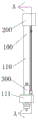
FIG. 1 is a schematic front view of the structure of the present invention;
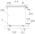
FIG. 2 is a schematic side sectional view of the structure of FIG. 1 at A-A according to the present invention;
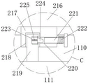
fig. 3 is a partially enlarged schematic view of the structure at B in fig. 2 according to the present invention;
fig. 4 is a partially enlarged schematic view of the structure at C in fig. 2 according to the present invention;
FIG. 5 is a schematic side view of the structure of the present invention;
fig. 6 is a partially enlarged schematic view of the structure at D in fig. 5 according to the present invention.
In the figure: 100. an LED lamp housing main body; 110. a housing; 111. a support plate; 200. a protection mechanism; 210. a storage box; 211. transferring the bin; 212. a rotating rod; 213. a first gear; 214. rotating the groove; 215. turning a handle; 216. a dust cloth; 217. connecting blocks; 218. a slot; 219. fixing the rod; 220. a card slot; 221. a push rod; 222. a first spring; 223. pressing a groove; 224. a clamping block; 225. a second spring; 226. a second gear; 300. a mobile support mechanism; 310. a nut; 311. a handle; 312. a universal wheel; 313. a movable groove; 314. a screw rod; 315. a support bar; 316. a moving groove; 317. moving the mass.
Detailed Description
The technical solutions in the embodiments of the present invention will be described clearly and completely with reference to the accompanying drawings in the embodiments of the present invention, and it is obvious that the described embodiments are only some embodiments of the present invention, not all embodiments. Based on the embodiments in the present invention, all other embodiments obtained by a person skilled in the art without creative work belong to the protection scope of the present invention.
Referring to fig. 1-6, the present invention provides an embodiment:
an LED lamp housing with a novel structure comprises an LED lamp housing main body 100, the LED lamp housing main body 100 comprises a housing 110, a supporting plate 111 is installed at the bottom end of the housing 110, a protection mechanism 200 is installed on the front face of the housing 110, the protection mechanism 200 comprises a storage box 210, the bottom end of the storage box 210 is fixedly connected with the top end of the housing 110, a rotary bin 211 is arranged at the bottom end of the storage box 210, a rotary rod 212 is arranged inside the rotary bin 211, two ends of the rotary rod 212 are connected with two sides of the inner wall of the rotary bin 211 through embedded bearings, a rotary groove 214 is arranged on one side of the inner wall of the rotary bin 211, a first gear 213 is sleeved on one side of the surface of the rotary rod 212, a rotary handle 215 is inserted into one side of the storage box 210, one end of the rotary handle 215 extends into the rotary groove 214, two sides of the surface of the rotary handle 215 are connected with the inner wall of the rotary groove 214 through the embedded bearings, a second gear 226 is sleeved on one side of the surface of the rotary handle 215, the first gear 213 is meshed with the second gear 226, the surface of the rotating rod 212 is wound with dustproof cloth 216, one end of the dustproof cloth 216 is fixedly connected with the surface of the rotating rod 212, the other end of the dustproof cloth 216 passes through the rotating bin 211 and extends to the outside of the rotating bin 211, both sides of the top end of the supporting plate 111 are fixedly connected with fixing rods 219, both sides of the bottom end of the dustproof cloth 216 are fixedly connected with connecting blocks 217, the bottom ends of the connecting blocks 217 are all provided with slots 218, the top ends of the fixing rods 219 extend to the inside of the slots 218, one side of each connecting block 217 is provided with a clamping groove 220, the surface of each fixing rod 219 is provided with a pressing groove 223, the inside of each pressing groove 223 is provided with a clamping block 224, one end of each clamping block 224 extends to the inside of each clamping groove 220, the inside of each pressing groove 223 is provided with a second spring 225, one end of each second spring 225 is fixedly connected with one side of each clamping block 224, the other end of each second spring 225 is fixedly connected with the inner wall of each pressing groove 223, one side of each connecting block 217 is provided with a push rod 221, one end of the push rod 221 extends into the slot 220, and the surface of the support plate 111 is provided with a movable support mechanism 300;
furthermore, a rubber pad is fixedly connected to the surface of the rotating handle 215, and inclined anti-slip lines are uniformly arranged on the surface of the rubber pad, so that the friction force of the hand of a user is improved through the rubber pad, and the rotating handle 215 is convenient to rotate by the user;
furthermore, the surface of the push rod 221 is sleeved with a first spring 222, one end of the first spring 222 is fixedly connected with one side of the push rod 221, the other end of the first spring 222 is fixedly connected with one side of the connecting block 217, the moving track of the push rod 221 is limited in the clamping groove 220 through the first spring 222, so that a user can use the push rod 221 conveniently, and the user does not need to pull the push rod 221 to reset through the resilience of the first spring 222;
furthermore, one side of the latch 224 is inclined, so that the friction force on the surface of the latch 224 is reduced, and the user can control the latch 224 to move into the slot 220 conveniently, thereby facilitating the use of the user;
furthermore, both sides of the fixture block 224 are fixedly connected with sliding blocks, both sides of the inner wall of the pressing groove 223 are provided with sliding grooves matched with the sliding blocks, the moving track of the fixture block 224 is limited through the sliding grooves and the sliding blocks, the stability of the fixture block 224 in the moving process is improved, and the fixture block 224 is prevented from deviating in the moving process;
further, the movable supporting mechanism 300 includes two sets of nuts 310, the nuts 310 are connected to each other through embedded bearings, the bottom ends of the two sets of nuts 310 are connected to the top end of the supporting plate 111 through embedded bearings, the two sides of the surface of the supporting plate 111 are both provided with movable grooves 313, the two sides of the nut 310 are both fixedly connected to handles 311, the two sides of the bottom end of the supporting plate 111 are both provided with universal wheels 312, the screw 310 is provided with a lead screw 314 inside, the bottom end of the lead screw 314 extends into the movable grooves 313, the bottom end of the lead screw 314 is fixedly connected to a supporting rod 315, the bottom end of the supporting rod 315 extends to the outside of the movable grooves 313 through the movable grooves 313, the two sides of the inner wall of the movable grooves 313 are both provided with movable grooves 316, the two sides of the supporting rod 315 are both fixedly connected to movable blocks 317, one end of each movable block 317 extends into the inside of the movable groove 316, a user pushes the housing 110, the device is moved by the rotation of the universal wheels 312, after the user adjusts the installation position, the handle 311 may be rotated, so that the support rod 315 supports the ground, and thus, the device may ensure good stability while facilitating the movement of the user to the housing 110, and the user may conveniently arrange the device.
The working principle is as follows: after the user installs the LED lamp screen in the housing 110, the user can rotate the rotating handle 215, the rotating handle 215 drives the second gear 226 to rotate, the second gear 226 drives the first gear 213 to rotate, the first gear 213 drives the rotating rod 212 to rotate, the dustproof cloth 216 wound on the rotating rod 212 is wound down from the rotating rod 212 and covers the LED lamp screen inside the housing 110, then the user can insert the fixing rod 219 into the insertion slot 218, the latch 224 abuts against the insertion slot 218 through the inclined surface, the latch 224 presses the second spring 225 under the stress and moves into the pressing slot 223, when the fixing rod 219 is inserted to a limit distance, the second spring 225 rebounds to reset, the latch 224 is driven by the resilience of the second spring 225 to be inserted into the slot 220 to complete the fixing, when the user needs to use the LED lamp screen in the housing 110, the user can press the push rod 221, the push rod 221 presses the first spring 222, the push rod 221 extrudes the latch 224 out of the slot 220, the fixture block 224 presses the second spring 225 under force and moves into the pressure groove 223, after the user releases the push rod 221, the first spring 222 rebounds to reset, the push rod 221 is driven to reset in the clamping groove 220 by the rebounding force of the first spring 222, then the user can move the connecting block 217, so that the fixing rod 219 moves out of the slot 218, and then the user can rotate the rotating handle 215 in the reverse direction again, so that the dustproof cloth 216 is rolled on the rotating rod 212 to reset;
the user can push the shell 110, through the rotation of universal wheel 312, make the device remove, the user is after finishing to the mounted position regulation of the device, the user can rotate handle 311, make handle 311 drive screw 310 rotate, under the effect of screw thread, and under the restriction of removal groove 316 and movable block 317 to lead screw 314 moving trajectory, make lead screw 314 remove in screw 310, lead screw 314 drives bracing piece 315 and removes in activity groove 313, and support ground, accomplish and fix.
It is obvious to a person skilled in the art that the invention is not restricted to details of the above-described exemplary embodiments, but that it can be implemented in other specific forms without departing from the spirit or essential characteristics of the invention. The present embodiments are therefore to be considered in all respects as illustrative and not restrictive, the scope of the invention being indicated by the appended claims rather than by the foregoing description, and all changes which come within the meaning and range of equivalency of the claims are therefore intended to be embraced therein. Any reference sign in a claim should not be construed as limiting the claim concerned.
Claims (6)
1. The utility model provides a LED lamp body of novel structure, includes LED lamp body main part (100), its characterized in that: the LED lamp housing main body (100) comprises a housing (110), a supporting plate (111) is installed at the bottom end of the housing (110), a protection mechanism (200) is installed on the front face of the housing (110), the protection mechanism (200) comprises a storage box (210), the bottom end of the storage box (210) is fixedly connected with the top end of the housing (110), a rotary bin (211) is arranged at the bottom end of the storage box (210), a rotary rod (212) is arranged inside the rotary bin (211), two ends of the rotary rod (212) are connected with two sides of the inner wall of the rotary bin (211) through embedded bearings, a rotary groove (214) is formed in one side of the inner wall of the rotary bin (211), a first gear (213) is sleeved on one side of the surface of the rotary rod (212), a rotary handle (215) is inserted into one side of the rotary handle (210), one end of the rotary handle (215) extends to the inside of the rotary groove (214), two sides of the surface of the rotary handle (215) are connected with the inner wall of the rotary groove (214) through the embedded bearings, the second gear (226) is sleeved on one side of the surface of the rotating handle (215), the first gear (213) is meshed with the second gear (226), dustproof cloth (216) is wound on the surface of the rotating rod (212), one end of the dustproof cloth (216) is fixedly connected with the surface of the rotating rod (212), the other end of the dustproof cloth (216) penetrates through the rotating bin (211) and extends to the outside of the rotating bin (211), fixing rods (219) are fixedly connected to two sides of the top end of the supporting plate (111), connecting blocks (217) are fixedly connected to two sides of the bottom end of the dustproof cloth (216), slots (218) are formed in the bottom ends of the connecting blocks (217), the top ends of the fixing rods (219) extend to the inside of the slots (218), clamping grooves (220) are formed in one side of the connecting blocks (217), pressing grooves (223) are formed in the surface of the fixing rods (219), the inside of indent (223) all is provided with fixture block (224), and the one end of fixture block (224) all extends to the inside of draw-in groove (220), the inside of indent (223) all is provided with second spring (225), the one end of second spring (225) all with one side fixed connection of fixture block (224), the other end of second spring (225) all with the inner wall fixed connection of indent (223), one side of connecting block (217) is provided with push rod (221), and the one end of push rod (221) extends to the inside of draw-in groove (220), the surface of backup pad (111) is provided with removal supporting mechanism (300).
2. The LED lamp housing with the novel structure as claimed in claim 1, wherein: the surface of the rotating handle (215) is fixedly connected with a rubber pad, and inclined anti-skidding lines are uniformly arranged on the surface of the rubber pad.
3. The LED lamp housing with the novel structure as claimed in claim 1, wherein: the surface of the push rod (221) is sleeved with a first spring (222), one end of the first spring (222) is fixedly connected with one side of the push rod (221), and the other end of the first spring (222) is fixedly connected with one side of the connecting block (217).
4. The LED lamp housing with the novel structure as claimed in claim 1, wherein: one side of the fixture block (224) is in an inclined plane shape.
5. The LED lamp housing with the novel structure as claimed in claim 1, wherein: the both sides of fixture block (224) all fixedly connected with slider, the both sides of indent (223) inner wall all seted up the spout with slider matched with.
6. The LED lamp housing with the novel structure as claimed in claim 1, wherein: the movable supporting mechanism (300) comprises two groups of nuts (310), the bottom ends of the two groups of nuts (310) are connected with the top end of a supporting plate (111) through embedded bearings, two sides of the surface of the supporting plate (111) are provided with movable grooves (313) in a penetrating mode, two sides of each nut (310) are fixedly connected with handles (311), two sides of the bottom end of the supporting plate (111) are provided with universal wheels (312), the inner portion of each nut (310) is provided with a lead screw (314), the bottom end of each lead screw (314) extends to the inner portion of each movable groove (313), the bottom end of each lead screw (314) is fixedly connected with a supporting rod (315), the bottom end of each supporting rod (315) extends to the outer portion of each movable groove (313) through each movable groove (313), two sides of the inner wall of each movable groove (313) are provided with movable grooves (316), two sides of each supporting rod (315) are fixedly connected with a movable block (317), and one end of the moving block (317) extends to the inside of the moving groove (316).
Priority Applications (1)
| Application Number | Priority Date | Filing Date | Title |
|---|---|---|---|
| CN202120727586.7U CN214535743U (en) | 2021-04-09 | 2021-04-09 | LED lamp housing with novel structure |
Applications Claiming Priority (1)
| Application Number | Priority Date | Filing Date | Title |
|---|---|---|---|
| CN202120727586.7U CN214535743U (en) | 2021-04-09 | 2021-04-09 | LED lamp housing with novel structure |
Publications (1)
| Publication Number | Publication Date |
|---|---|
| CN214535743U true CN214535743U (en) | 2021-10-29 |
Family
ID=78272688
Family Applications (1)
| Application Number | Title | Priority Date | Filing Date |
|---|---|---|---|
| CN202120727586.7U Expired - Fee Related CN214535743U (en) | 2021-04-09 | 2021-04-09 | LED lamp housing with novel structure |
Country Status (1)
| Country | Link |
|---|---|
| CN (1) | CN214535743U (en) |
Cited By (1)
| Publication number | Priority date | Publication date | Assignee | Title |
|---|---|---|---|---|
| CN114645529A (en) * | 2022-05-05 | 2022-06-21 | 蒙城县水利局建筑工程队 | Temporary support device is built to ecological bank protection of water conservancy |
-
2021
- 2021-04-09 CN CN202120727586.7U patent/CN214535743U/en not_active Expired - Fee Related
Cited By (2)
| Publication number | Priority date | Publication date | Assignee | Title |
|---|---|---|---|---|
| CN114645529A (en) * | 2022-05-05 | 2022-06-21 | 蒙城县水利局建筑工程队 | Temporary support device is built to ecological bank protection of water conservancy |
| CN114645529B (en) * | 2022-05-05 | 2024-02-09 | 蒙城县水利局建筑工程队 | Temporary support device is built to ecological bank protection of water conservancy |
Similar Documents
| Publication | Publication Date | Title |
|---|---|---|
| CN214535743U (en) | LED lamp housing with novel structure | |
| CN219513471U (en) | Socket converter | |
| CN212366180U (en) | 5G outdoor antenna convenient to installation | |
| CN112919243A (en) | Shaftless take-up device for double-disc type cage winch capable of collecting cables rapidly | |
| CN210131829U (en) | Remote transmission platform with screen cleaning function | |
| CN217751489U (en) | Snatch stable manipulator of effect | |
| CN216149576U (en) | LED fluorescent powder glue anti-precipitation device | |
| CN216249986U (en) | Data processing device for deep learning | |
| CN213458899U (en) | Rolling type policy publicity column for village happy | |
| CN210274202U (en) | Trinity dustproof plastic cell-phone shell | |
| CN214671496U (en) | Warning sign convenient to place for electric power engineering construction | |
| CN211918551U (en) | Vehicle-mounted player with adjustable rotation angle | |
| CN212313606U (en) | Travelling car convenient to mechanical equipment installation | |
| CN212084525U (en) | Be used for engineering construction management show all-in-one | |
| CN209971976U (en) | Anti-falling pen | |
| CN112397925A (en) | Improved structure of computer interface | |
| CN216119103U (en) | Combined computer graphics teaching device | |
| CN207635469U (en) | A kind of new wind turbine of used in communication machine room | |
| CN213988133U (en) | LED display screen rapid configuration host computer | |
| CN215181677U (en) | Portable computer all-in-one machine | |
| CN214356433U (en) | Electric bicycle support convenient to install lithium cell | |
| CN217348557U (en) | Steel coil longitudinal cutting dust-binding device | |
| CN212531088U (en) | Lifting device for processing dehydrated vegetables | |
| CN214591823U (en) | Cylindrical sound box | |
| CN214688831U (en) | Easel is used in fine arts teaching convenient to dismantle and accomodate |
Legal Events
| Date | Code | Title | Description |
|---|---|---|---|
| GR01 | Patent grant | ||
| GR01 | Patent grant | ||
| CF01 | Termination of patent right due to non-payment of annual fee | ||
| CF01 | Termination of patent right due to non-payment of annual fee |
Granted publication date: 20211029 |