CN214529770U - Cutting device for processing water-soft cotton knitted fabric - Google Patents
Cutting device for processing water-soft cotton knitted fabric Download PDFInfo
- Publication number
- CN214529770U CN214529770U CN202023226852.2U CN202023226852U CN214529770U CN 214529770 U CN214529770 U CN 214529770U CN 202023226852 U CN202023226852 U CN 202023226852U CN 214529770 U CN214529770 U CN 214529770U
- Authority
- CN
- China
- Prior art keywords
- wall
- fixedly connected
- transmission frame
- roller
- dust
- Prior art date
- Legal status (The legal status is an assumption and is not a legal conclusion. Google has not performed a legal analysis and makes no representation as to the accuracy of the status listed.)
- Active
Links
Images


Abstract
The utility model discloses a processing of soft cotton knitted fabric of water is with tailorring device, including the transmission frame, the inner wall of transmission frame rotates and is connected with first pivot, the first transfer roller of outer wall fixedly connected with of first pivot, the inner wall of transmission frame and the one side that is located first transfer roller rotate and be connected with the second pivot, the outer wall of transmission frame rotates and is connected with the cleaning roller, the outer wall fixedly connected with brush of cleaning roller, the dust absorption hole has been seted up to the outer wall of cleaning roller and the both sides that are located the brush. The rotation through spring one drives the activity ring and rotates, and eccentric setting makes the outer wall of activity ring and the outer wall contact friction of brush produce static, makes the brush adsorb the dust of surface fabric outer wall, and on partial dust got into dust adhesion device through dust absorption hole, adsorb the dust through dust adhesion device, and this device passes through the mating reaction of devices such as dust absorption hole, brush, cleans the surface of surface fabric, makes the effect of cutting better.
Description
Technical Field
The utility model belongs to the technical field of knitted fabric, concretely relates to processing of soft cotton knitted fabric is with tailorring device.
Background
The cotton knitted fabric is always popular with consumers due to the characteristics of comfortable wearing, good air permeability, nature and environmental protection, and becomes one of the most popular and popular garment fabrics in the market. In order to meet the market demand for high-grade pure cotton fabrics, manufacturers at home and abroad carry out a great deal of research on high-grade processing of pure cotton knitted fabrics, and the grade of the fabrics is improved from various aspects of hand feeling, luster, stability, functionality and the like of the fabrics. The methods for improving the hand feeling of cotton knitted fabrics can be mainly classified into the following methods: the water flexibility of the fabric is improved by adopting specially spun yarns, in particular to cotton yarns with low twist; obtaining special hand feeling through a mechanical finishing mode; the hand feeling of the pure cotton fabric is improved by a processing method combining mechanical processing and chemical treatment.
The fabric cutting machine on the market at present is of many kinds, has manually, has automatically, but most cutter has such some problems:
1. when the fabric is cut, a cleaning device is not arranged, and dust on the surface of the fabric cannot be cleaned, so that the quality of the fabric is influenced;
2. when the fabric is cut, the two ends of the fabric cannot be well tensioned, so that the fabric is not conveniently fixed, the fabric is not cut well, and the fabric is wasted.
SUMMERY OF THE UTILITY MODEL
An object of the utility model is to provide a processing of soft cotton knitted fabric of water is with tailorring device to propose current processing of soft cotton knitted fabric of water in the solution above-mentioned background art with tailorring device in the use, owing to when cutting the surface fabric, not be provided with cleaning device, can not take up the surface fabric both ends well, thereby influence the surface fabric quality, there is the problem of extravagant surface fabric.
In order to achieve the above object, the utility model provides a following technical scheme: a cutting device for processing a water-soft cotton knitted fabric comprises a transmission frame, wherein the inner wall of the transmission frame is rotatably connected with a first rotating shaft, the outer wall of the first rotating shaft is fixedly connected with a first transmission roller, the inner wall of the transmission frame is rotatably connected with a second rotating shaft at one side of the first transmission roller, the outer wall of the transmission frame is rotatably connected with a cleaning roller, the outer wall of the cleaning roller is fixedly connected with a hairbrush, dust suction holes are formed in the outer wall of the cleaning roller and positioned at two sides of the hairbrush, the outer wall of the second rotating shaft is sleeved with a first spring, a movable ring is arranged on the outer wall of the second rotating shaft, a positioning roller is rotatably connected between the inner walls of the transmission frame, a fixed rod is fixedly connected with the inner wall of the positioning roller, a movable rod is sleeved on the outer wall of the fixed rod, one end, far away from the fixed rod, of the movable rod is fixedly connected with a first magnet, and the outer wall of the transmission frame is fixedly connected with an installation frame, the top outer wall fixedly connected with cylinder of installing the frame, the one end fixedly connected with mounting panel of cylinder, the inner wall fixed mounting of mounting panel has cutting blade.
Preferably, the outer walls of the first rotating shaft and the second rotating shaft are provided with belts, and the first rotating shaft is in transmission connection with the second rotating shaft through the belts.
Preferably, the outer wall of one side of the movable ring is fixedly connected with the outer wall of the first spring, and the movable ring and the first spring are distributed in a linear array along the horizontal direction of the second rotating shaft.
Preferably, the inner wall of the cleaning roller is adhered with a dust adhering device.
Preferably, the quantity of registration roller is two, and two the registration roller sets up in the both sides of installation frame, it is connected with the second transfer roller to rotate between the inner wall of transmission frame.
Preferably, the outer wall of the fixed rod is sleeved with a second spring, the outer wall of the second spring is fixedly connected with the inner wall of the movable rod, the top of the inner wall of the transmission frame is fixedly connected with a second magnet, and the outer wall of the first magnet is magnetically connected with the outer wall of the second magnet.
Preferably, the inner wall both sides of transmission frame have all been seted up the spout, the both sides outer wall of mounting panel and the inner wall sliding connection of spout.
Compared with the prior art, the beneficial effects of the utility model are that:
1. convey the surface fabric through first transfer roller and second transfer roller, it rotates to drive the second pivot through the rotation of first pivot, the rotation of second pivot drives spring one and rotates, the rotation of spring one drives the loose ring and rotates, eccentric setting makes the outer wall of loose ring and the outer wall contact friction of brush produce static, make the brush adsorb the dust of surface fabric outer wall, partial dust passes through on the dust absorption hole gets into dust adhesion device, adsorb the dust through dust adhesion device, this device passes through the dust absorption hole, under the mating reaction of devices such as brush, clean the surface of surface fabric, make the effect of cutting better, guarantee the quality of surface fabric.
2. Rotation through the registration roller makes dead lever, movable rod and magnet rotate along with it, and when the outer wall of magnet one and the outer wall contact of magnet two, two magnet magnetism attract mutually, fix the surface fabric to make things convenient for cutting blade to cut the surface fabric, this device makes cutting blade when cutting the surface fabric, through the setting of both sides registration roller, fixes the surface fabric, guarantees cutting effect.
Drawings
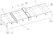
Fig. 1 is a schematic perspective view of the present invention;
FIG. 2 is a schematic side view of the present invention;
FIG. 3 is a schematic view of the structure of the cleaning roller of the present invention;
FIG. 4 is a schematic view of a part of the structure of the cleaning roller of the present invention;
FIG. 5 is a schematic view of the movable ring of the present invention;
FIG. 6 is a schematic view of the structure of the positioning roller of the present invention;
fig. 7 is a schematic view of the structure of the movable rod of the present invention.
In the figure: 1. a transmission rack; 2. a first rotating shaft; 3. a first transfer roller; 4. a second rotating shaft; 5. a cleaning roller; 6. a brush; 7. a dust collection hole; 8. a first spring; 9. a movable ring; 10. a dust adhering means; 11. a positioning roller; 12. fixing the rod; 13. a movable rod; 14. a magnet I; 15. installing a frame; 16. a cylinder; 17. mounting a plate; 18. a cutting blade; 19. a chute; 20. a second transfer roller.
Detailed Description
The technical solutions in the embodiments of the present invention will be described clearly and completely with reference to the accompanying drawings in the embodiments of the present invention, and it is obvious that the described embodiments are only some embodiments of the present invention, not all embodiments. Based on the embodiments in the present invention, all other embodiments obtained by a person skilled in the art without creative work belong to the protection scope of the present invention.
Referring to fig. 1-7, the present invention provides a technical solution: a cutting device for processing a water-soft cotton knitted fabric comprises a transmission frame 1, wherein the inner wall of the transmission frame 1 is rotatably connected with a first rotating shaft 2, the outer wall of the first rotating shaft 2 is fixedly connected with a first transmission roller 3, the inner wall of the transmission frame 1 is rotatably connected with a second rotating shaft 4 positioned on one side of the first transmission roller 3, the outer wall of the transmission frame 1 is rotatably connected with a cleaning roller 5, the outer wall of the cleaning roller 5 is fixedly connected with a hairbrush 6, the outer wall of the cleaning roller 5 is provided with dust suction holes 7 positioned on two sides of the hairbrush 6, the outer wall of the second rotating shaft 4 is sleeved with a spring I8, the outer wall of the second rotating shaft 4 is provided with a movable ring 9, a positioning roller 11 is rotatably connected between the inner walls of the transmission frame 1, the inner wall of the positioning roller 11 is fixedly connected with a fixed rod 12, the outer wall of the fixed rod 12 is sleeved with a movable rod 13, one end, far away from the fixed rod 12, of the movable rod 13 is fixedly connected with a magnet I14, the outer wall of the transmission frame 1 is fixedly connected with an installation rack 15, the outer wall fixedly connected with cylinder 16 of the top of installing frame 15, the one end fixedly connected with mounting panel 17 of cylinder 16, the inner wall fixed mounting of mounting panel 17 has cutting blade 18.
In this embodiment, convey the surface fabric through first transfer roller 3 and second transfer roller 20, rotation through first pivot 2 drives second pivot 4 and rotates, rotation of second pivot 4 drives spring 8 and rotates, rotation of spring 8 drives movable ring 9 and rotates, eccentric setting makes the outer wall of movable ring 9 and the outer wall contact friction of brush 6 produce static, make brush 6 adsorb the dust of surface fabric outer wall, some dust gets into on dust adhesion device 10 through dust absorption hole 7, adsorb the dust through dust adhesion device 10, rotation through registration roller 11 makes dead lever 12, movable rod 13 and magnet 14 rotate thereupon, when the outer wall of magnet 14 and the outer wall contact of magnet two, two magnet magnetism attract each other, fix the surface fabric, thereby make things convenient for cutting blade 18 to cut the surface fabric.
Specifically, the outer walls of the first rotating shaft 2 and the second rotating shaft 4 are provided with belts, and the first rotating shaft 2 is in transmission connection with the second rotating shaft 4 through the belts.
In the present embodiment, the rotation of the first rotating shaft 2 provides power for the rotation of the second rotating shaft 4 through the arrangement of the belt.
Specifically, the outer wall of one side of the movable ring 9 is fixedly connected with the outer wall of the first spring 8, and the movable ring 9 and the first spring 8 are distributed in a linear array along the horizontal direction of the second rotating shaft 4.
In the embodiment, the swing amplitude of the movable ring 9 is increased by arranging the first spring 8, so that the movable ring 9 is in better contact with the outer wall of the brush 6.
Specifically, the inner wall of the cleaning roller 5 is bonded with the dust adhering means 10.
In the present embodiment, the dust entering the inside of the cleaning roller 5 through the dust suction hole 7 is adhered to the dust adhering means 10, and cleaning of the dust is achieved by the dust adhering means 10.
Specifically, the number of the positioning rollers 11 is two, the two positioning rollers 11 are arranged on two sides of the installation rack 15, and the second conveying roller 20 is rotatably connected between the inner walls of the transmission rack 1.
In this embodiment, through the setting of two registration rollers 11, make the surface fabric when being cut, can be by better compressing tightly, guarantee the cutting effect, carry the surface fabric through the cooperation of first transfer roller 3 and second transfer roller 20.
Specifically, the outer wall of the fixed rod 12 is sleeved with a second spring, the outer wall of the second spring is fixedly connected with the inner wall of the movable rod 13, the top of the inner wall of the transmission frame 1 is fixedly connected with a second magnet, and the outer wall of the first magnet 14 is magnetically connected with the outer wall of the second magnet.
In this embodiment, through the setting of spring two, make things convenient for the rebound motion of movable rod 13, when the outer wall of magnet one 14 and the outer wall contact of magnet two, two magnet magnetism attract each other, fix the surface fabric to make things convenient for cutting blade 18 to cut the surface fabric.
Specifically, the inner wall both sides of transmission frame 1 have all been seted up spout 19, and the both sides outer wall of mounting panel 17 and the inner wall sliding connection of spout 19.
In this embodiment, the mounting plate 17 can better drive the cutting blade 18 to move up and down by the arrangement of the sliding groove 19, so as to avoid the inclination of cutting.
The utility model discloses a theory of operation and use flow: during the use, convey the surface fabric through first transfer roller 3 and second transfer roller 20, rotation through first pivot 2 drives second pivot 4 and rotates, rotation of second pivot 4 drives spring 8 and rotates, the rotation of spring 8 drives movable ring 9 and rotates, eccentric setting makes the outer wall of movable ring 9 and the outer wall contact friction of brush 6 produce static, make brush 6 adsorb the dust of surface fabric outer wall, some dust gets into on dust adhesion device 10 through dust absorption hole 7, adsorb the dust through dust adhesion device 10, rotation through registration roller 11 makes dead lever 12, movable rod 13 and magnet 14 rotate thereupon, when the outer wall of magnet 14 and the outer wall contact of magnet two, two magnet magnetism attract each other, fix the surface fabric, thereby make things convenient for cutting blade 18 to cut the surface fabric.
Although embodiments of the present invention have been shown and described, it will be appreciated by those skilled in the art that changes, modifications, substitutions and alterations can be made in these embodiments without departing from the principles and spirit of the invention, the scope of which is defined in the appended claims and their equivalents.
Claims (7)
1. The utility model provides a processing of soft cotton knitted fabric is with tailorring device, includes transmission frame (1), its characterized in that: the inner wall of the transmission frame (1) is rotatably connected with a first rotating shaft (2), the outer wall of the first rotating shaft (2) is fixedly connected with a first transmission roller (3), the inner wall of the transmission frame (1) is rotatably connected with a second rotating shaft (4) on one side of the first transmission roller (3), the outer wall of the transmission frame (1) is rotatably connected with a cleaning roller (5), the outer wall of the cleaning roller (5) is fixedly connected with a brush (6), the outer wall of the cleaning roller (5) is provided with dust suction holes (7) on two sides of the brush (6), the outer wall of the second rotating shaft (4) is sleeved with a first spring (8), the outer wall of the second rotating shaft (4) is provided with a movable ring (9), a positioning roller (11) is rotatably connected between the inner walls of the transmission frame (1), the inner wall of the positioning roller (11) is fixedly connected with a fixed rod (12), the outer wall of dead lever (12) has cup jointed movable rod (13), the one end fixedly connected with magnet (14) of dead lever (12) is kept away from in movable rod (13), the outer wall fixedly connected with installation frame (15) of transmission frame (1), the top outer wall fixedly connected with cylinder (16) of installation frame (15), the one end fixedly connected with mounting panel (17) of cylinder (16), the inner wall fixed mounting of mounting panel (17) has cutting blade (18).
2. The cutting device for processing the water-soft cotton knitted fabric according to claim 1, characterized in that: the outer wall of first pivot (2) and second pivot (4) is provided with the belt, first pivot (2) are connected through belt transmission with second pivot (4).
3. The cutting device for processing the water-soft cotton knitted fabric according to claim 1, characterized in that: the outer wall of one side of the movable ring (9) is fixedly connected with the outer wall of the first spring (8), and the movable ring (9) and the first spring (8) are distributed in a linear array mode along the horizontal direction of the second rotating shaft (4).
4. The cutting device for processing the water-soft cotton knitted fabric according to claim 1, characterized in that: the inner wall of the cleaning roller (5) is adhered with a dust adhesion device (10).
5. The cutting device for processing the water-soft cotton knitted fabric according to claim 1, characterized in that: the quantity of registration roller (11) is two, and two registration roller (11) set up in the both sides of installation frame (15), it is connected with second transfer roller (20) to rotate between the inner wall of transmission frame (1).
6. The cutting device for processing the water-soft cotton knitted fabric according to claim 1, characterized in that: the outer wall of the fixed rod (12) is sleeved with a second spring, the outer wall of the second spring is fixedly connected with the inner wall of the movable rod (13), the top of the inner wall of the transmission frame (1) is fixedly connected with a second magnet, and the outer wall of the first magnet (14) is magnetically connected with the outer wall of the second magnet.
7. The cutting device for processing the water-soft cotton knitted fabric according to claim 1, characterized in that: the inner wall both sides of transmission frame (1) have all been seted up spout (19), the both sides outer wall of mounting panel (17) and the inner wall sliding connection of spout (19).
Priority Applications (1)
| Application Number | Priority Date | Filing Date | Title |
|---|---|---|---|
| CN202023226852.2U CN214529770U (en) | 2020-12-28 | 2020-12-28 | Cutting device for processing water-soft cotton knitted fabric |
Applications Claiming Priority (1)
| Application Number | Priority Date | Filing Date | Title |
|---|---|---|---|
| CN202023226852.2U CN214529770U (en) | 2020-12-28 | 2020-12-28 | Cutting device for processing water-soft cotton knitted fabric |
Publications (1)
| Publication Number | Publication Date |
|---|---|
| CN214529770U true CN214529770U (en) | 2021-10-29 |
Family
ID=78297190
Family Applications (1)
| Application Number | Title | Priority Date | Filing Date |
|---|---|---|---|
| CN202023226852.2U Active CN214529770U (en) | 2020-12-28 | 2020-12-28 | Cutting device for processing water-soft cotton knitted fabric |
Country Status (1)
| Country | Link |
|---|---|
| CN (1) | CN214529770U (en) |
-
2020
- 2020-12-28 CN CN202023226852.2U patent/CN214529770U/en active Active
Similar Documents
| Publication | Publication Date | Title |
|---|---|---|
| CN214529770U (en) | Cutting device for processing water-soft cotton knitted fabric | |
| CN102793513B (en) | Vacuum cleaner and suction nozzle thereof | |
| CN113388995B (en) | Weaving sanding device | |
| CN109381131B (en) | Mop driving mechanism on automatic mopping machine | |
| CN112974176A (en) | Fine hair collection device is used in spinning machine production | |
| CN211888192U (en) | Automatic cleaning device for outer wall impurities for mechanical production and processing of blocky workpieces | |
| CN113073459B (en) | Velvet product edge cutting device for textile production | |
| CN108994036A (en) | One kind using Scissoring device based on textile cloth production | |
| CN210287889U (en) | Surface fabric coating cleaning device | |
| CN212247488U (en) | Belt cleaning device for textile processing | |
| CN210139267U (en) | Composite equipment is used in production of motorcycle deep bead | |
| CN211077793U (en) | Weaving processing is with weaving cloth conveyer | |
| CN210383783U (en) | Mop driving mechanism on automatic mopping machine | |
| CN213962228U (en) | Spiral brush piece type brush roller | |
| CN214782784U (en) | Cloth surface debris cleaning device for spinning | |
| CN219560599U (en) | Spinning roller cleaning device | |
| CN215849947U (en) | Mouth rubbing device on automatic hemming machine of valve port braided bag | |
| CN215481434U (en) | Wool cleaning device | |
| CN220352421U (en) | Elastic warp knitting fabric napping device | |
| CN213113864U (en) | A belt cleaning device for clothing production | |
| CN218989532U (en) | Take-up structure of secondary twisting and chenille yarn machine | |
| CN219289338U (en) | Cleaning accessory | |
| CN211155556U (en) | Combined rolling brush in dust collector floor brush | |
| CN219965726U (en) | Board surface cleaning device for integrated circuit board production | |
| CN220788921U (en) | Spun yarn cradle floss roll shaft convenient for cleaning entangled flowers |
Legal Events
| Date | Code | Title | Description |
|---|---|---|---|
| GR01 | Patent grant | ||
| GR01 | Patent grant |