Background
The lift, the lift operation platform is a kind of multi-functional lifting mechanical equipment, can be divided into fixed and movable type, guide rail type, crank arm type, cut fork type, chain type and loading and unloading platform, etc., the principle of the lift is that hydraulic oil is formed certain pressure by the vane pump, enter the bottom end of the hydraulic cylinder through oil filter, flame-proof type electromagnetic directional valve, choke valve, pilot-operated check valve, balance valve, make the piston of the hydraulic cylinder move upwards, promote the heavy object, the lift is usually used for rescuing and decorating, the lift is divided into following movable type, fixed type, wall-hanging type, etc..
Present lift platform on the market, the condition that the slope appears easily in the lift in-process leads to goods to drop and elevating gear's the incline and fall, and it all is single fluid pressure type elevation structure moreover mostly, and fluid pressure type elevation structure can't work after hydraulic system is out of order easily, leads to the construction effect poor.
SUMMERY OF THE UTILITY MODEL
An object of the utility model is to provide a lift with protective structure to solve the problem that proposes among the above-mentioned background art.
In order to achieve the above object, the utility model provides a following technical scheme: a lift with a protective structure comprises a rack, a lifting driving box arranged on the rack and a lifting assembly arranged on the lifting driving box, wherein a partition plate is arranged in the lifting driving box, vertically arranged and used for dividing an inner cavity of the lifting driving box into a first cavity and a second cavity; the bottom sides of the first cavity and the second cavity are respectively provided with a sliding chute, the first cavity and the second cavity are respectively and movably connected with a screw rod through a rotating shaft, each screw rod is provided with two screw thread sections with opposite screw directions, each screw thread section is sleeved with a screw sleeve, the bottom end of each screw sleeve is connected with the sliding chute in a sliding manner through a sliding rod, and the screw sleeve is hinged with a support rod; frame plates are further arranged at the tops of the inner sides of the first cavity and the second cavity, elongated slots are formed in the two side ends of each frame plate, sliding blocks are arranged on the inner sides of the frame plates, and the free ends of the two supporting rods penetrate through the elongated slots and are hinged to the bottom end portions of the sliding blocks.
Preferably, two guide sleeves are installed at the top of the outer side of the lifting driving box, guide columns are arranged on the inner sides of the guide sleeves, and the bottom ends of the guide columns are connected with the top ends of the sliding blocks through connecting blocks.
Preferably, the outer sides of the first chamber and the second chamber are provided with a transmission column in transmission connection with the screw, and the transmission column is sleeved with a first bevel gear.
Preferably, the frame is provided with a first driving assembly, the first driving assembly comprises a motor and a second bevel gear connected to the shaft end of the motor, and the second bevel gear is in meshing transmission with the first bevel gear.
Preferably, the end part of the guide column extending out of the guide sleeve is connected with a lifting assembly, the lifting assembly comprises a bottom plate, a lifting rod and a protective frame, and the inner side of the bottom plate is provided with the lifting plate capable of moving along the side wall of the bottom plate.
Preferably, the bottom side of the bottom plate is provided with a second driving assembly and a lifting rod, the lifting rod is formed by cross-connecting two rod frames, and the bottom end of the lifting rod is connected with a sliding seat in sliding connection with the bottom side of the bottom plate.
Preferably, a sliding frame is fixed at the bottom end of the lifting plate, two sliding sleeves are sleeved on the sliding frame, and the free ends of the lifting rods are respectively hinged with the two sliding sleeves.
Preferably, a sliding frame is fixed at the bottom end of the lifting plate, two sliding sleeves are sleeved on the sliding frame, and the free ends of the lifting rods are respectively hinged with the two sliding sleeves.
Preferably, the protection frame is installed in the lifter plate top, and second drive assembly is the cylinder and it is connected with the slide, and it promotes the slide and removes.
Compared with the prior art, the beneficial effects of the utility model are that:
the utility model discloses a two-stage goes up and down, wherein the one-level is mechanical lift, and another one-level is hydraulic lift, and the two-stage goes up and down can simultaneous working and perhaps still carry out the lift work after hydraulic system is malfunctioning, excellent in use effect, and mechanical elevation structure all adopts the better structure of stability to constitute with hydraulic pressure elevation structure moreover, and construction stability and protection nature are better.
Detailed Description
The technical solutions in the embodiments of the present invention will be described clearly and completely with reference to the accompanying drawings in the embodiments of the present invention, and it is obvious that the described embodiments are only some embodiments of the present invention, not all embodiments. Based on the embodiments in the present invention, all other embodiments obtained by a person skilled in the art without creative work belong to the protection scope of the present invention.
In the description of the present invention, it should be noted that the terms "vertical", "upper", "lower", "horizontal", and the like indicate orientations or positional relationships based on the orientations or positional relationships shown in the drawings, and are only for convenience of description and simplification of description, but do not indicate or imply that the device or element referred to must have a specific orientation, be constructed in a specific orientation, and be operated, and thus should not be construed as limiting the present invention.
In the description of the present invention, it should also be noted that, unless otherwise explicitly specified or limited, the terms "disposed," "mounted," "connected," and "connected" are to be construed broadly, e.g., as meaning either a fixed connection, a removable connection, or an integral connection; can be mechanically or electrically connected; they may be connected directly or indirectly through intervening media, or they may be interconnected between two elements. The specific meaning of the above terms in the present invention can be understood according to specific situations by those skilled in the art.
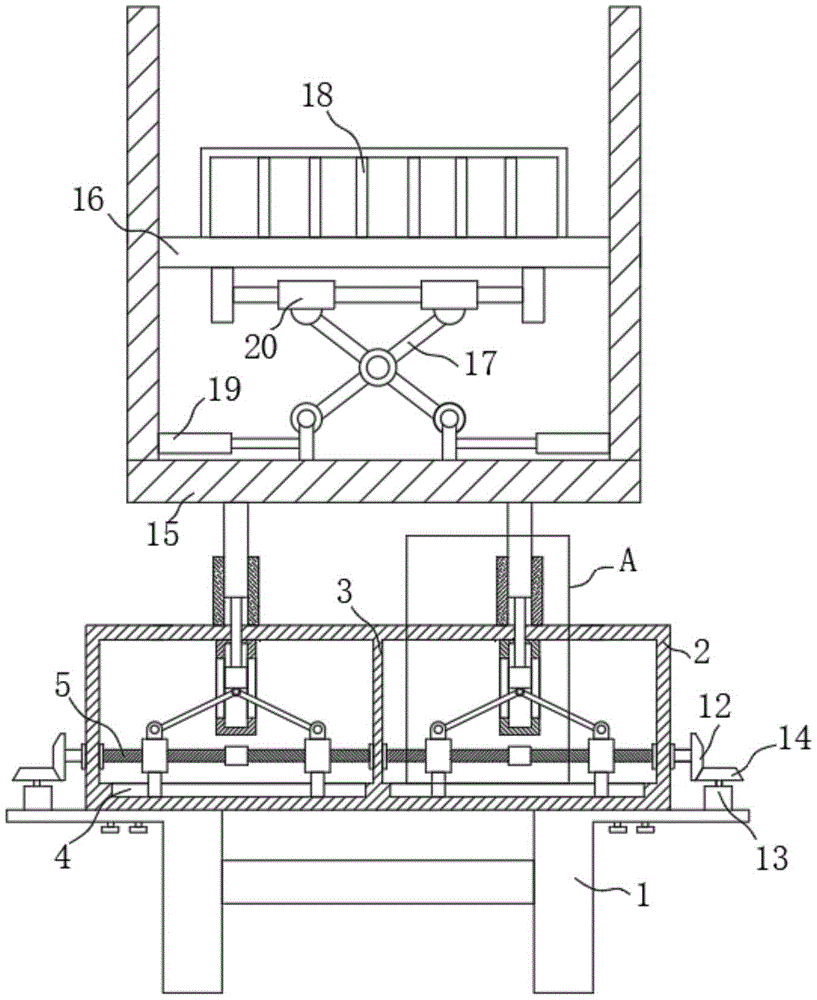
Referring to fig. 1-2, the present invention provides a technical solution: a lift with a protective structure comprises a frame 1, a lifting driving box 2 arranged on the frame 1 and a lifting assembly arranged on the lifting driving box 2, wherein a partition plate 3 is arranged in the lifting driving box 2, and the partition plate 3 is vertically arranged and divides an inner cavity of the lifting driving box 2 into a first cavity and a second cavity; the bottom sides of the first cavity and the second cavity are respectively provided with a sliding chute 4, the first cavity and the second cavity are respectively and movably connected with a screw rod 5 through a rotating shaft, each screw rod 5 is provided with two screw thread sections with opposite screw directions, each screw thread section is sleeved with a screw sleeve 6, the bottom end of each screw sleeve 6 is in sliding connection with the sliding chute 4 through a sliding rod, and the screw sleeve 6 is hinged with a support rod 7; frame plates 8 are further arranged at the tops of the inner sides of the first cavity and the second cavity, elongated slots are formed in two side ends of each frame plate 8, sliding blocks 9 are arranged on the inner sides of the frame plates 8, and the free ends of the two support rods 7 penetrate through the elongated slots and are hinged to the bottom end portions of the sliding blocks 9.
In this embodiment, two guide sleeves 10 have been installed at the outside top of lift drive case 2, and guide post 11 is equipped with to guide sleeve 10 inboard, and the top of slider 9 is connected through the connecting block to guide post 11 bottom.
In this embodiment, the outer ends of the first chamber and the second chamber are provided with a transmission column in transmission connection with the screw 5, and the transmission column is sleeved with a first bevel gear 12.
In this embodiment, the frame 1 is provided with a first driving assembly, the first driving assembly includes a motor 13 and a second bevel gear 14 connected to a shaft end of the motor 13, and the second bevel gear 14 is in meshing transmission with the first bevel gear 12.
In this embodiment, the end of the guide post 11 extending out of the guide sleeve 10 is connected to a lifting assembly, the lifting assembly includes a bottom plate 15, a lifting plate 16, a lifting rod 17 and a protection frame 18, and the inner side of the bottom plate 15 is provided with the lifting plate 16 capable of moving along the side wall thereof.
In this embodiment, the second driving assembly 19 and the lifting rod 17 are installed on the bottom side of the bottom plate 15, the lifting rod 17 is formed by cross-connecting two rod frames, and the bottom end of the lifting rod 17 is connected with a slide seat in sliding contact with the bottom side of the bottom plate 15.
In this embodiment, a sliding frame is fixed at the bottom end of the lifting plate 16, two sliding sleeves 20 are sleeved on the sliding frame, and the free ends of the lifting rods 17 are respectively hinged with the two sliding sleeves 20.
In the embodiment, the protection frame 18 is mounted on the top of the lifting plate 16, and the second driving assembly 19 is a cylinder and is connected to the carriage, which pushes the carriage to move.
The utility model adopts two-stage lifting, wherein one stage is mechanical lifting, the other stage is hydraulic lifting, the two-stage lifting can work simultaneously and still lift after the failure of the hydraulic system, the use effect is good, and the mechanical lifting structure and the hydraulic lifting structure are both formed by structures with better stability, the construction stability and the protection performance are better;
the mechanical lifting is that a motor 13 drives a second bevel gear 14, the second bevel gear 14 is meshed with and driven by a first bevel gear 12, a screw 5 is driven by the first bevel gear 12 to run, the screw 5 drives two screw sleeves 6 on the screw to move, a supporting rod 7 is driven by the screw sleeves 6, the supporting rod 7 drives a sliding block 9 to move upwards along the inner side of a frame plate 8 and jack a guide post 11, and the whole lifting assembly is driven to move upwards by the guide post 11;
the lifting component is hydraulically lifted, the sliding seat is pushed to move through the air cylinder, the lifting rod 17 is unfolded, so that the lifting plate 16 moves along the inner side of the bottom plate 15, the supporting stability is better because the bottom plate 15 moves along the inner side of the bottom plate 15, and the protective frame 18 on the lifting plate 16 can provide better construction protection.
It is worth noting that: whole lift is connected with power and total control button, and it realizes controlling it through total control button, because the equipment that control button matches is equipment commonly used, belongs to current mature technology, no longer gives unnecessary details its electric connection relation and specific circuit structure here.
Although embodiments of the present invention have been shown and described, it will be appreciated by those skilled in the art that changes, modifications, substitutions and alterations can be made in these embodiments without departing from the principles and spirit of the invention, the scope of which is defined in the appended claims and their equivalents.