CN214467730U - Monitoring device of thermal control automation equipment of thermal power plant - Google Patents
Monitoring device of thermal control automation equipment of thermal power plant Download PDFInfo
- Publication number
- CN214467730U CN214467730U CN202120611728.3U CN202120611728U CN214467730U CN 214467730 U CN214467730 U CN 214467730U CN 202120611728 U CN202120611728 U CN 202120611728U CN 214467730 U CN214467730 U CN 214467730U
- Authority
- CN
- China
- Prior art keywords
- fixedly connected
- frame
- mounting
- mounting panel
- power plant
- Prior art date
- Legal status (The legal status is an assumption and is not a legal conclusion. Google has not performed a legal analysis and makes no representation as to the accuracy of the status listed.)
- Active
Links
Images


Abstract
The utility model discloses a monitoring device of thermal power plant's thermal control automation equipment, including the mounting panel, the fixed surface of mounting panel is connected with stop device, the surface of mounting panel is provided with the construction bolt, the mounting panel is installed through the construction bolt, the outside of mounting panel is provided with the connecting rod, the utility model relates to a supervisory equipment technical field. This monitoring device of thermal power plant's thermal control automation equipment, reached and utilized the construction bolt to install mounting panel and wall body, the staff holds the handle, drive the connecting rod motion, it is corresponding with stop device to install the piece, utilize stop device to carry out the joint to the installation piece, can install the camera fast, the installation effectiveness is improved, the later stage of being convenient for is dismantled and is maintained, set up strutting arrangement, be convenient for according to the control demand, adjust the control angle of camera, monitor equipment, the safety performance is improved, make things convenient for the staff to operate, satisfy user demand's purpose.
Description
Technical Field
The utility model relates to a supervisory equipment field, more specifically say, relate to a monitoring device of thermal power plant's thermal control automation equipment.
Background
A thermal power plant, referred to as a thermal power plant, is a plant that produces electric energy using a combustible (e.g., coal) as a fuel. The basic production process is as follows: when the fuel is burnt, water is heated to generate steam, chemical energy of the fuel is converted into heat energy, the steam pressure pushes a steam turbine to rotate, the heat energy is converted into mechanical energy, and then the steam turbine drives a generator to rotate, so that the mechanical energy is converted into electric energy. In order to ensure the safety of thermal control automation equipment of a thermal power plant, monitoring devices are generally installed around the thermal control automation equipment to monitor the thermal control automation equipment in real time. At present, the monitoring device of current thermal power plant thermal control automation equipment, the structure is relatively fixed, and the staff of not being convenient for installs fast and dismantles, influences installation and maintenance efficiency, and the staff of being not convenient for of camera adjusts, and application range is limited, can't satisfy the user demand.
SUMMERY OF THE UTILITY MODEL
1. Technical problem to be solved
Aiming at the problems that the prior monitoring device of the thermal control automation equipment of the thermal power plant has relatively fixed structure, is inconvenient for workers to rapidly install and disassemble, influences the installation and maintenance efficiency, is inconvenient for workers to adjust, has limited use range and cannot meet the use requirement, the utility model aims to provide the monitoring device of the thermal control automation equipment of the thermal power plant, which can realize that a mounting plate, a limiting device, a mounting bolt, a connecting rod, a mounting block, a mounting frame, a fixing frame, a rotating frame, a camera, a supporting device and a handle form a whole, the mounting plate and a wall body are installed by the mounting bolt, the operator holds the handle to drive the connecting rod to move, the mounting block corresponds to the limiting device, the mounting block is clamped by the limiting device, and the camera can be rapidly installed, the installation efficiency is improved, the later stage of being convenient for is dismantled and is maintained, sets up strutting arrangement, is convenient for adjust the control angle of camera according to the control demand, monitors equipment, improves the security performance, makes things convenient for the staff to operate, satisfies the user demand.
2. Technical scheme
In order to solve the above problems, the utility model adopts the following technical proposal.
The utility model provides a monitoring device of thermal power plant's thermal control automation equipment, includes the mounting panel, the fixed surface of mounting panel is connected with stop device, the surface of mounting panel is provided with the construction bolt, the mounting panel is installed through the construction bolt, the outside of mounting panel is provided with the connecting rod, the tip fixedly connected with installation piece of connecting rod, stop device and installation piece joint, the one end fixedly connected with installing frame of installation piece is kept away from to the connecting rod, the inner wall fixedly connected with mount of installing frame, the tip of mount rotates and is connected with the rotating turret, the bottom fixedly connected with camera of rotating turret, the top fixedly connected with strutting arrangement of rotating turret, the rotating turret passes through strutting arrangement and installing frame joint, the top fixedly connected with handle of installing frame.
Preferably, stop device is including fixed frame, fixed frame and mounting panel fixed connection, the inner wall fixedly connected with kelly of fixed frame, the inner wall of installation piece is provided with the draw-in groove, the kelly is corresponding with the draw-in groove, the inner wall fixedly connected with slide bar of fixed frame, slide bar sliding connection has the slider, the lateral wall fixedly connected with supporting spring of slider, supporting spring cup joints with the slide bar, the tip fixedly connected with pull ring of slider, the lateral wall fixedly connected with fixture block of pull ring, fixture block and installation piece joint.
Preferably, the supporting device comprises a limiting frame, the limiting frame is fixedly connected with the end of the rotating frame, a compression spring is fixedly connected to the inner wall of the limiting frame, the limiting frame is fixedly connected with a supporting block through the compression spring, a supporting rod is fixedly connected to the surface of the supporting block, the supporting rod is slidably connected with the limiting frame, an extrusion block is fixedly connected to the top of the supporting rod, a bump is fixedly connected to the inner wall of the mounting frame at an equal angle, and the extrusion block is clamped with the gap of the bump.
3. Advantageous effects
Compared with the prior art, the utility model has the advantages of: the installation plate is installed on the wall body by the installation bolt, a worker holds the handle to drive the connecting rod to move, the installation block corresponds to the limiting device, the limiting device is used for clamping the installation block, the camera can be quickly installed, the installation efficiency is improved, the later-stage disassembly and maintenance are convenient, the supporting device is arranged, the monitoring angle of the camera can be conveniently adjusted according to the monitoring requirement, the equipment is monitored, the safety performance is improved, the worker can conveniently operate, the limiting device is arranged to be conveniently clamped with the installation block, when the camera needs to be installed, the pull ring is pulled to drive the sliding block to move, the elastic potential energy of the supporting spring is increased, and the clamping block is driven to move, the installation block is butted with the fixing frame, the clamping rod corresponds to the clamping groove, then the pull ring is loosened, the elastic potential energy of the supporting spring is converted into kinetic energy, the sliding block is driven to reset, the clamping block is clamped on the installation block, the camera can be quickly installed, the installation efficiency is improved, the later-stage disassembly and maintenance of workers are facilitated, the supporting device is arranged, the workers can conveniently adjust the angle of the camera, the extrusion block is pulled to move downwards to drive the supporting rod to move to drive the supporting block to move, the elastic potential energy of the compression spring is increased to remove the limit of the extrusion block and the lug, the rotating frame is rotated to adjust the angle of the camera, the extrusion block is loosened again, the elastic potential energy of the compression spring is converted into kinetic energy to drive the extrusion block to reset, the extrusion block is clamped with the lug again, the camera can be quickly fixed, the workers can conveniently adjust the camera, the installation plate, the limiting device and the limiting device are achieved, Mounting bolt, the connecting rod, the installation piece, the installing frame, the mount, the rotating turret, the camera, strutting arrangement constitutes a whole with the handle, utilize mounting bolt to install mounting panel and wall body, the staff holds the handle, drive the connecting rod motion, it is corresponding with stop device to install the piece, utilize stop device to carry out the joint to the installation piece, can install the camera fast, the installation effectiveness is improved, the later stage of being convenient for is dismantled and is maintained, set up strutting arrangement, be convenient for according to the control demand, adjust the control angle of camera, monitor equipment, the security performance is improved, make things convenient for the staff to operate, satisfy user demand's purpose.
Drawings
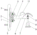
Fig. 1 is a schematic view of the overall external structure of the present invention;
FIG. 2 is a schematic view of the overall internal structure of the present invention;
fig. 3 is a schematic view of a partial enlarged structure at a in fig. 2 according to the present invention;
fig. 4 is a schematic diagram of a partial enlarged structure at B of fig. 2 according to the present invention.
The reference numbers in the figures illustrate:
1. mounting a plate; 2. a limiting device; 21. a fixing frame; 22. a clamping rod; 23. a card slot; 24. a slide bar; 25. a slider; 26. a support spring; 27. a pull ring; 28. a clamping block; 3. installing a bolt; 4. a connecting rod; 5. mounting blocks; 6. installing a frame; 7. a fixed mount; 8. a rotating frame; 9. a camera; 10. a support device; 101. a limiting frame; 102. a compression spring; 103. a support block; 104. a support bar; 105. extruding the block; 106. a bump; 11. a handle.
Detailed Description
The drawings in the embodiments of the present invention will be combined; the technical scheme in the embodiment of the utility model is clearly and completely described; obviously; the described embodiments are only some of the embodiments of the present invention; rather than all embodiments. Based on the embodiment of the utility model; all other embodiments obtained by a person skilled in the art without making any inventive step; all belong to the protection scope of the utility model.
Example 1:
referring to fig. 1-4, the present invention provides a technical solution: the utility model provides a monitoring device of thermal power plant's thermal control automation equipment, including mounting panel 1, the fixed surface of mounting panel 1 is connected with stop device 2, the surface of mounting panel 1 is provided with construction bolt 3, mounting panel 1 installs through construction bolt 3, the outside of mounting panel 1 is provided with connecting rod 4, the tip fixedly connected with installation piece 5 of connecting rod 4, stop device 2 and 5 joints of installation piece, the one end fixedly connected with installing frame 6 of installation piece 5 is kept away from to connecting rod 4, the inner wall fixedly connected with mount 7 of installing frame 6, the tip of mount 7 is rotated and is connected with rotating turret 8, the bottom fixedly connected with camera 9 of rotating turret 8, the top fixedly connected with strutting arrangement 10 of rotating turret 8, rotating turret 8 passes through strutting arrangement 10 and 6 joints of installing frame, the top fixedly connected with handle 11 of installing frame 6. Mounting panel 1, stop device 2, construction bolt 3, connecting rod 4, installation piece 5, the installing frame 6, mount 7, the rotating turret 8, camera 9, strutting arrangement 10 constitutes a whole with handle 11, utilize construction bolt 3 to install mounting panel 1 and wall body, the staff holds handle 11, drive connecting rod 4 motion, it is corresponding with stop device 2 to install piece 5, utilize stop device 2 to carry out the joint to installation piece 5, can install camera 9 fast, the installation effectiveness is improved, the later stage of being convenient for is dismantled and is maintained, set up strutting arrangement 10, be convenient for according to the control demand, adjust camera 9's control angle, monitor equipment, the security performance is improved, make things convenient for the staff to operate.
Example 2:
referring to fig. 3, a monitoring device for thermal control automation equipment of a thermal power plant is substantially the same as that in embodiment 1, and further, the limiting device 2 includes a fixing frame 21, the fixing frame 21 is fixedly connected to the mounting plate 1, a clamping rod 22 is fixedly connected to an inner wall of the fixing frame 21, a clamping groove 23 is formed in an inner wall of the mounting block 5, the clamping rod 22 corresponds to the clamping groove 23, a sliding rod 24 is fixedly connected to an inner wall of the fixing frame 21, the sliding rod 24 is slidably connected to a sliding block 25, a supporting spring 26 is fixedly connected to a side wall of the sliding block 25, the supporting spring 26 is sleeved with the sliding rod 24, a pull ring 27 is fixedly connected to an end of the sliding block 25, a clamping block 28 is fixedly connected to a side wall of the pull ring 27, and the clamping block 28 is clamped to the mounting block 5. Set up stop device 2, be convenient for carry out the joint with installation piece 5, when needs install camera 9, pulling pull ring 27, drive the motion of slider 25, increase supporting spring 26's elastic potential energy, drive the motion of fixture block 28, dock installation piece 5 with fixed frame 21, kelly 22 is corresponding with draw-in groove 23, then loosen pull ring 27, supporting spring 26 elastic potential energy turns into kinetic energy, it resets to drive slider 25, make fixture block 28 carry out the joint to installation piece 5, can install camera 9 fast, and the installation effectiveness is improved, make things convenient for staff's later stage to dismantle the maintenance.
Example 3:
referring to fig. 4, a monitoring device for thermal control automation equipment of a thermal power plant is substantially the same as that in embodiment 1, and further, a supporting device 10 includes a limiting frame 101, the limiting frame 101 is fixedly connected to an end of the rotating frame 8, a compression spring 102 is fixedly connected to an inner wall of the limiting frame 101, the limiting frame 101 is fixedly connected to a supporting block 103 through the compression spring 102, a supporting rod 104 is fixedly connected to a surface of the supporting block 103, the supporting rod 104 is slidably connected to the limiting frame 101, an extruding block 105 is fixedly connected to a top of the supporting rod 104, a bump 106 is fixedly connected to an inner wall of the mounting frame 6 at an equal angle, and the extruding block 105 is in gap clamping connection with the bump 106. Set up strutting arrangement 10, be convenient for the staff adjusts the angle of camera 9, pulling extrusion piece 105 downstream, drive bracing piece 104 motion, drive supporting shoe 103 motion, increase compression spring 102's elastic potential energy, remove the restriction of extrusion piece 105 and lug 106, rotate the rotating turret 8, adjust the angle of camera 9, loosen extrusion piece 105 again, compression spring 102 elastic potential energy turns into kinetic energy, drive extrusion piece 105 and reset, carry out the joint with lug 106 again, can fix camera 9 fast, make things convenient for the staff to adjust.
The above; is only a preferred embodiment of the present invention; however, the scope of protection of the present invention is not limited thereto; any person skilled in the art is within the technical scope of the present disclosure; according to the technical scheme of the utility model and the improvement conception, equivalent substitution or change is carried out; are all covered by the protection scope of the utility model.
Claims (3)
1. The utility model provides a monitoring device of thermal control automation equipment of thermal power plant, includes mounting panel (1), its characterized in that: the surface of the mounting plate (1) is fixedly connected with a limiting device (2), the surface of the mounting plate (1) is provided with a mounting bolt (3), the mounting plate (1) is mounted through the mounting bolt (3), the outside of the mounting plate (1) is provided with a connecting rod (4), the end part of the connecting rod (4) is fixedly connected with a mounting block (5), the limiting device (2) is connected with the mounting block (5) in a clamping manner, one end of the connecting rod (4) far away from the mounting block (5) is fixedly connected with a mounting frame (6), the inner wall of the mounting frame (6) is fixedly connected with a fixing frame (7), the end part of the fixing frame (7) is rotatably connected with a rotating frame (8), the bottom of the rotating frame (8) is fixedly connected with a camera (9), the top of the rotating frame (8) is fixedly connected with a supporting device (10), and the rotating frame (8) is connected with the mounting frame (6) in a clamping manner through the supporting device (10), the top of the mounting frame (6) is fixedly connected with a handle (11).
2. The monitoring device of the thermal control automation equipment of the thermal power plant according to claim 1, characterized in that: stop device (2) are including fixed frame (21), fixed frame (21) and mounting panel (1) fixed connection, the inner wall fixedly connected with kelly (22) of fixed frame (21), the inner wall of installation piece (5) is provided with draw-in groove (23), kelly (22) are corresponding with draw-in groove (23), the inner wall fixedly connected with slide bar (24) of fixed frame (21), slide bar (24) sliding connection has slider (25), the lateral wall fixedly connected with supporting spring (26) of slider (25), supporting spring (26) cup joint with slide bar (24), the tip fixedly connected with pull ring (27) of slider (25), the lateral wall fixedly connected with fixture block (28) of pull ring (27), fixture block (28) and installation piece (5) joint.
3. The monitoring device of the thermal control automation equipment of the thermal power plant according to claim 1, characterized in that: support arrangement (10) include spacing frame (101), spacing frame (101) and rotating turret (8) tip fixed connection, the inner wall fixedly connected with compression spring (102) of spacing frame (101), spacing frame (101) are through compression spring (102) fixedly connected with supporting shoe (103), the fixed surface of supporting shoe (103) is connected with bracing piece (104), bracing piece (104) and spacing frame (101) sliding connection, the top fixedly connected with extrusion piece (105) of bracing piece (104), angle fixedly connected with lug (106) such as the inner wall of installing frame (6), the clearance joint of extrusion piece (105) and lug (106).
Priority Applications (1)
| Application Number | Priority Date | Filing Date | Title |
|---|---|---|---|
| CN202120611728.3U CN214467730U (en) | 2021-03-23 | 2021-03-23 | Monitoring device of thermal control automation equipment of thermal power plant |
Applications Claiming Priority (1)
| Application Number | Priority Date | Filing Date | Title |
|---|---|---|---|
| CN202120611728.3U CN214467730U (en) | 2021-03-23 | 2021-03-23 | Monitoring device of thermal control automation equipment of thermal power plant |
Publications (1)
| Publication Number | Publication Date |
|---|---|
| CN214467730U true CN214467730U (en) | 2021-10-22 |
Family
ID=78160332
Family Applications (1)
| Application Number | Title | Priority Date | Filing Date |
|---|---|---|---|
| CN202120611728.3U Active CN214467730U (en) | 2021-03-23 | 2021-03-23 | Monitoring device of thermal control automation equipment of thermal power plant |
Country Status (1)
| Country | Link |
|---|---|
| CN (1) | CN214467730U (en) |
Cited By (1)
| Publication number | Priority date | Publication date | Assignee | Title |
|---|---|---|---|---|
| CN114776997A (en) * | 2022-03-23 | 2022-07-22 | 呼伦贝尔安泰热电有限责任公司海拉尔热电厂 | Thermal control instrument installation device for thermal control of power plant |
-
2021
- 2021-03-23 CN CN202120611728.3U patent/CN214467730U/en active Active
Cited By (2)
| Publication number | Priority date | Publication date | Assignee | Title |
|---|---|---|---|---|
| CN114776997A (en) * | 2022-03-23 | 2022-07-22 | 呼伦贝尔安泰热电有限责任公司海拉尔热电厂 | Thermal control instrument installation device for thermal control of power plant |
| CN114776997B (en) * | 2022-03-23 | 2023-10-10 | 呼伦贝尔安泰热电有限责任公司海拉尔热电厂 | Thermal control instrument mounting device for thermal control of power plant |
Similar Documents
| Publication | Publication Date | Title |
|---|---|---|
| CN214467730U (en) | Monitoring device of thermal control automation equipment of thermal power plant | |
| CN103904444A (en) | Power transmission line grounding wire horizontal installation device | |
| CN110808550B (en) | Cable anti-shake device for power engineering installation | |
| CN212086710U (en) | A shell protector for building monitored control system | |
| CN210266644U (en) | Monitoring installation device of photovoltaic power station | |
| CN216112998U (en) | Solar camera convenient to overhaul | |
| CN207034046U (en) | A kind of resistance to spring support used | |
| CN214851589U (en) | Building engineering quality safety supervision and management alarm device | |
| CN217816087U (en) | Monitoring device of thermal control automation equipment of thermal power plant | |
| CN211352307U (en) | Electric power remote monitoring device | |
| CN209642053U (en) | A kind of electrical network parameter monitoring device based on DSP | |
| CN208860620U (en) | A kind of basis electromechanical equipment state monitoring apparatus | |
| CN207294821U (en) | Deashing imaging device in State of Blast Furnace | |
| CN214306149U (en) | Device for electric power production inspection | |
| CN217634971U (en) | Monitoring device of thermal control automation equipment of thermal power plant | |
| CN105156835A (en) | Clutch type climbing construction unit | |
| CN212434010U (en) | Real examination device of instructing of thermal power factory operation | |
| CN220748467U (en) | Wind-powered electricity generation blade lightning protection structure | |
| CN212840385U (en) | Remote monitoring device for electric power automation equipment | |
| CN214467186U (en) | Intelligent iron tower monitoring equipment | |
| CN210167870U (en) | Novel hydroelectric generating set generator rotor structure | |
| CN210578949U (en) | Novel intelligent monitoring equipment | |
| CN213880052U (en) | Engineering supervision and construction informatization device | |
| CN215548312U (en) | Disassembling and assembling support for end cover of generator | |
| CN113915041B (en) | Mixed nozzle for impulse turbine |
Legal Events
| Date | Code | Title | Description |
|---|---|---|---|
| GR01 | Patent grant | ||
| GR01 | Patent grant |