CN214457204U - High-efficient integrated processing system of high oiliness washing wastewater - Google Patents
High-efficient integrated processing system of high oiliness washing wastewater Download PDFInfo
- Publication number
- CN214457204U CN214457204U CN202023118692.XU CN202023118692U CN214457204U CN 214457204 U CN214457204 U CN 214457204U CN 202023118692 U CN202023118692 U CN 202023118692U CN 214457204 U CN214457204 U CN 214457204U
- Authority
- CN
- China
- Prior art keywords
- treatment device
- oil
- device shell
- liquid inlet
- active motor
- Prior art date
- Legal status (The legal status is an assumption and is not a legal conclusion. Google has not performed a legal analysis and makes no representation as to the accuracy of the status listed.)
- Active
Links
Images


Abstract
The utility model discloses a high-efficiency comprehensive treatment system for high-oil-content cleaning wastewater, which comprises a treatment device shell, wherein a liquid inlet hopper is arranged on the treatment device shell, a liquid inlet pipe is arranged below the liquid inlet hopper and penetrates through the treatment device shell, a cleaning mechanism is arranged on one side of the liquid inlet pipe and comprises an active motor, the active motor is electrically connected with an external power supply, a connecting shaft is arranged on one side of the active motor and is connected with the active motor, a rotating roller is arranged on the periphery of the connecting shaft and penetrates through the rotating roller, the rotating roller is connected with the active motor, a matching groove is arranged inside the rotating roller, a moving rod is arranged on one side of the matching groove and is clamped with the matching groove, and the device brushes the waste oil passing through the surface of an ultrafiltration membrane through a moving brush, thereby greatly enhancing the filtering effect of the ultrafiltration membrane and preventing the condition of unable filtering.
Description
Technical Field
The utility model relates to a high oily washing wastewater treatment field particularly, relates to a high-efficient integrated processing system of high oily washing wastewater.
Background
With the continuous development of modern industry, the application of various mineral oils represented by cutting fluid and lubricating oil in industrial production is increasingly wide and frequent, and the problem of treating oily wastewater caused by the application is also gradually a research hotspot in the field of environmental protection. Wherein, the gravity oil removal operation is the most simple and convenient, which can achieve better treatment effect, but needs a pre-demulsification process; the extraction and distillation can recycle the oil in the wastewater, but the extraction and distillation are only suitable for the wastewater with simpler oil composition, and the added medicament in the extraction process can bring new environmental risk, and the distillation process is easy to cause the problems of coking and the like; the biological treatment has the advantages of low energy consumption and the like, but specific strains need to be cultured, the oil content of the wastewater cannot be too high, and the biological treatment is not suitable for the heavy metal-containing oily wastewater.
Current oily waste water treatment device, when carrying out membrane separation, one side of filtration membrane can contain a large amount of waste oil to make under long-time filtration, the waste oil can continuous save, thereby make the filter effect variation, and then lead to the unable filterable condition.
An effective solution to the problems in the related art has not been proposed yet.
SUMMERY OF THE UTILITY MODEL
An object of the utility model is to provide a high-efficient integrated processing system of high oiliness washing wastewater to solve the problem that proposes in the above-mentioned background art.
In order to achieve the above object, the utility model provides a following technical scheme:
a high-efficiency comprehensive treatment system for high-oil-content cleaning wastewater comprises a treatment device shell, wherein a liquid inlet hopper is arranged on the treatment device shell, a liquid inlet pipe is arranged below the liquid inlet hopper and penetrates through the treatment device shell, a cleaning mechanism is arranged on one side of the liquid inlet pipe and comprises an active motor, the active motor is electrically connected with an external power supply, a connecting shaft is arranged on one side of the active motor and is connected with the active motor, a rotary roller is arranged on the periphery of the connecting shaft and penetrates through the rotary roller, the rotary roller is connected with the active motor, a matching groove is formed in the rotary roller, a moving rod is arranged on one side of the matching groove and is clamped with the matching groove, a moving brush is arranged below the moving rod and is connected with the moving rod, remove and be equipped with the filter under the brush, the inside milipore filter that is equipped with of filter, the filter has the stock solution room, just stock solution room top with the milipore filter is connected, the filter bilateral symmetry is equipped with the flowing groove, the flowing groove has an oil pipe, an oil pipe with the flowing groove is connected, an oil pipe has the oil storage room.
Furthermore, a rotary bearing is arranged inside the treatment device shell, the outer ring of the rotary bearing is connected with the treatment device shell, and the inner ring of the rotary bearing is connected with the connecting shaft.
Furthermore, a liquid outlet pipe is arranged on one side of the liquid storage chamber.
Furthermore, an oil discharge pipe is arranged on one side of the oil storage chamber.
Furthermore, the movable guide rail is connected with the movable rod, and two sides of the movable guide rail are attached to the inner wall of the treatment device shell.
Furthermore, a base is arranged below the treatment device shell.
Compared with the prior art, the utility model discloses following beneficial effect has:
(1) the oily waste liquid poured into the liquid inlet hopper enters the treatment device shell through the liquid inlet pipe by arranging the treatment device shell, the waste oil on the surface of the ultrafiltration membrane is cleaned when the ultrafiltration membrane in the filter plate is filtered and then enters the filter plate, the driving motor drives the rotary drum to rotate through the connecting shaft, so that the movable rod is driven to reciprocate by the matching groove when the rotary drum rotates, so that the movable brush is driven to move in a reciprocating manner when the movable rod moves in a reciprocating manner, the waste oil on the surface of the ultrafiltration membrane is brushed into the flow groove by the movable brush when the movable brush moves in a reciprocating manner, thereby make waste oil pass through in the flow groove oil outlet pipe gets into the oil storage chamber, this device brushes the waste oil on crossing the milipore filter surface through removing the brush to make the filter effect of milipore filter strengthen greatly, prevent to take place unable filterable condition.
(2) The utility model discloses a convenient placing device, including the brush, the brush is fixed with the movable rod, through setting up swivel bearing to reach the rotatory purpose of swivel bearing fixed connection axle, through setting up the drain pipe, thereby make the waste liquid after the filtration flow through the drain pipe, through setting up the oil extraction pipe, thereby make the waste liquid under the brush flow through the oil extraction pipe, through setting up movable guide rail, thereby reach the purpose that makes things convenient for fixed movable rod to remove, through setting up the base, thereby reach the purpose that makes things convenient for placer.
Drawings
In order to more clearly illustrate the embodiments of the present invention or the technical solutions in the prior art, the drawings required to be used in the embodiments will be briefly described below, and it is obvious that the drawings in the following description are only some embodiments of the present invention, and for those skilled in the art, other drawings can be obtained according to these drawings without creative efforts.
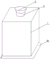
FIG. 1 is a schematic diagram of a high-efficiency comprehensive treatment system for high-oil content cleaning wastewater according to an embodiment of the present invention;
FIG. 2 is a front sectional view of a treatment device housing in a high efficiency integrated treatment system for high oil content cleaning wastewater according to an embodiment of the present invention;
FIG. 3 is a sectional top view of the enclosure of an abatement device in a high efficiency integrated treatment system for high oil content wastewater in accordance with an embodiment of the present invention;
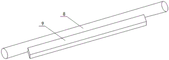
fig. 4 is a perspective view of a movable rod in a high-efficiency comprehensive treatment system for high-oil content cleaning wastewater according to an embodiment of the present invention.
Reference numerals:
1. a treatment device housing; 2. a liquid inlet hopper; 3. a liquid inlet pipe; 4. an active motor; 5. a connecting shaft; 6. rotating the drum; 7. a mating groove; 8. a travel bar; 9. moving the brush; 10. a filter plate; 11. ultrafiltration membranes; 12. a liquid storage chamber; 13. a flow channel; 14. an oil outlet pipe; 15. an oil storage chamber; 16. a rotating bearing; 17. a liquid outlet pipe; 18. an oil discharge pipe; 19. a moving guide rail; 20. a base.
Detailed Description
The following, with reference to the drawings and the detailed description, further description of the present invention is made:
the first embodiment is as follows:
referring to fig. 1-4, a high-efficiency comprehensive treatment system for high-oil content cleaning wastewater according to an embodiment of the present invention includes a treatment device housing 1, a liquid inlet hopper 2 is disposed on the treatment device housing 1, a liquid inlet pipe 3 is disposed under the liquid inlet hopper 2, the liquid inlet pipe 3 penetrates through the treatment device housing 1, a cleaning mechanism is disposed at one side of the liquid inlet pipe 3, the cleaning mechanism includes a driving motor 4, the driving motor 4 is electrically connected to an external power source, a connecting shaft 5 is disposed at one side of the driving motor 4, the connecting shaft 5 is connected to the driving motor 4, a rotary drum 6 is disposed at the periphery of the connecting shaft 5, the connecting shaft 5 penetrates through the rotary drum 6, the rotary drum 6 is connected to the driving motor 4, a matching groove 7 is disposed inside the rotary drum 6, and a moving rod 8 is disposed at one side of the matching groove 7, the carriage release lever 8 with cooperation recess 7 looks joint, carriage release lever 8 has movable brush 9, movable brush 9 with carriage release lever 8 is connected, movable brush 9 has filter 10, the inside milipore filter 11 that is equipped with of filter 10, filter 10 has stock solution room 12, just stock solution room 12 top with milipore filter 11 is connected, filter 10 bilateral symmetry is equipped with flow cell 13, flow cell 13 has out oil pipe 14, go out oil pipe 14 with flow cell 13 is connected, it has oil storage chamber 15 to go out oil pipe 14.
Through the above scheme of the utility model, through setting up treatment device shell 1, thereby make the oily waste liquid that advances of liquid inlet bucket 2 enter treatment device shell 1 through feed liquor pipe 3, get into in filter 10 after ultrafiltration membrane 11 in filter 10 filters, when needing to clear up the waste oil that has ultrafiltration membrane 11 surface, through the rotatory cylinder 6 of connecting axle 5 drive of driving motor 4 through connecting axle 5, thereby make rotatory cylinder 6 drive carriage release lever 8 reciprocating motion through cooperation recess 7 when rotatory, and then make carriage release lever 8 reciprocating motion drive and move brush 9 reciprocating motion, when making moving brush 9 reciprocating motion, brush the waste oil on ultrafiltration membrane 11 surface in flow groove 13 through moving brush 9, thereby make the waste oil pass through oil outlet pipe 14 and get into in oil storage chamber 15 in flow groove 13, this device brushes the waste oil that crosses ultrafiltration membrane 11 surface through moving brush 9, thereby greatly enhancing the filtering effect of the ultrafiltration membrane 11 and preventing the condition of incapability of filtering.
Example two:
referring to fig. 1-4, a rotary bearing 16 is arranged inside the treatment device housing 1, an outer ring of the rotary bearing 16 is connected with the treatment device housing 1, an inner ring of the rotary bearing is connected with the connecting shaft 5, a liquid outlet pipe 17 is arranged on one side of the liquid storage chamber 12, an oil discharge pipe 18 is arranged on one side of the oil storage chamber 15, a moving guide rail 19 is arranged on one side of the moving rod 8, the moving guide rail 19 is connected with the moving rod 8, two sides of the moving guide rail 19 are attached to the inner wall of the treatment device housing 1, and a base 20 is arranged below the treatment device housing 1.
Through the above technical scheme of the utility model, through setting up swivel bearing 16, thereby reach the purpose of swivel bearing 16 fixed connection axle 5 rotations, through setting up drain pipe 17, thereby make the waste liquid after the filtration flow through drain pipe 17, through setting up oil extraction pipe 18, thereby make the waste liquid under the brush flow through oil extraction pipe 18, through setting up movable guide 19, thereby reach the purpose that makes things convenient for fixed carriage release lever 8 to remove, through setting up base 20, thereby reach the purpose that makes things convenient for placer.
For the convenience of understanding the technical solution of the present invention, the following detailed description is made on the working principle or the operation mode of the present invention in the practical process.
In practical application, the treatment device shell 1 is arranged, so that oily waste liquid poured into the liquid inlet hopper 2 enters the treatment device shell 1 through the liquid inlet pipe 3, the ultrafiltration membrane 11 in the filter plate 10 enters the filter plate 10 after being filtered, when the waste oil on the surface of the ultrafiltration membrane 11 needs to be cleaned, the rotary roller 6 is driven to rotate through the driving motor 4 through the connecting shaft 5, so that the rotary roller 6 drives the movable rod 8 to reciprocate through the matching groove 7 when rotating, further the movable rod 8 drives the movable brush 9 to reciprocate when reciprocating, when the movable brush 9 reciprocates, the waste oil on the surface of the ultrafiltration membrane 11 is brushed into the flow groove 13 through the movable brush 9, so that the waste oil enters the oil storage chamber 15 through the oil outlet pipe 14 in the flow groove 13, the device brushes the waste oil on the surface of the ultrafiltration membrane 11 through the movable brush 9, and the filtering effect of the ultrafiltration membrane 11 is greatly enhanced, prevent to take place unable filterable circumstances, through setting up swivel bearing 16, thereby reach the purpose of swivel bearing 16 fixed connection axle 5 rotations, through setting up drain pipe 17, thereby make the waste liquid after the filtration flow out through drain pipe 17, through setting up oil extraction pipe 18, thereby make the waste liquid under the brush flow out through oil extraction pipe 18, through setting up movable guide 19, thereby reach the purpose that makes things convenient for fixed carriage release lever 8 to remove, through setting up base 20, thereby reach the purpose that makes things convenient for placer.
Although embodiments of the present invention have been shown and described, it will be appreciated by those skilled in the art that changes, modifications, substitutions and alterations can be made in these embodiments without departing from the principles and spirit of the invention, the scope of which is defined in the appended claims and their equivalents.
Claims (6)
1. The high-efficiency comprehensive treatment system for the high-oil content cleaning wastewater comprises a treatment device shell (1) and is characterized in that a liquid inlet hopper (2) is arranged on the treatment device shell (1), a liquid inlet pipe (3) is arranged below the liquid inlet hopper (2), the liquid inlet pipe (3) penetrates through the treatment device shell (1), a cleaning mechanism is arranged on one side of the liquid inlet pipe (3) and comprises an active motor (4), the active motor (4) is electrically connected with an external power supply, a connecting shaft (5) is arranged on one side of the active motor (4), the connecting shaft (5) is connected with the active motor (4), a rotary roller (6) is arranged on the periphery of the connecting shaft (5), the connecting shaft (5) penetrates through the rotary roller (6), the rotary roller (6) is connected with the active motor (4), a matching groove (7) is formed in the rotary roller (6), cooperation recess (7) one side is equipped with carriage release lever (8), carriage release lever (8) with cooperation recess (7) looks joint, carriage release lever (8) have removal brush (9), remove brush (9) with carriage release lever (8) are connected, removal brush (9) have filter (10), filter (10) inside is equipped with milipore filter (11), filter (10) have stock solution room (12), just stock solution room (12) top with milipore filter (11) are connected, filter (10) bilateral symmetry is equipped with flow groove (13), flow groove (13) have out oil pipe (14), go out oil pipe (14) with flow groove (13) are connected, it has oil storage chamber (15) to go out oil pipe (14).
2. The high-efficiency comprehensive treatment system for the high-oil content cleaning wastewater according to claim 1, characterized in that a rotary bearing (16) is arranged inside the treatment device shell (1), the outer ring of the rotary bearing (16) is connected with the treatment device shell (1), and the inner ring is connected with the connecting shaft (5).
3. The high-efficiency comprehensive treatment system for the high-oil content cleaning wastewater as claimed in claim 1, wherein a liquid outlet pipe (17) is arranged on one side of the liquid storage chamber (12).
4. The high-efficiency comprehensive treatment system for high-oil content cleaning wastewater according to claim 1, characterized in that an oil discharge pipe (18) is arranged on one side of the oil storage chamber (15).
5. The high-efficiency comprehensive treatment system for the high-oil content cleaning wastewater according to claim 1, characterized in that a moving guide rail (19) is arranged on one side of the moving rod (8), the moving guide rail (19) is connected with the moving rod (8), and two sides of the moving guide rail (19) are attached to the inner wall of the treatment device shell (1).
6. The high-efficiency comprehensive treatment system for the high-oil content cleaning wastewater according to claim 5, characterized in that a base (20) is arranged below the treatment device shell (1).
Priority Applications (1)
| Application Number | Priority Date | Filing Date | Title |
|---|---|---|---|
| CN202023118692.XU CN214457204U (en) | 2020-12-23 | 2020-12-23 | High-efficient integrated processing system of high oiliness washing wastewater |
Applications Claiming Priority (1)
| Application Number | Priority Date | Filing Date | Title |
|---|---|---|---|
| CN202023118692.XU CN214457204U (en) | 2020-12-23 | 2020-12-23 | High-efficient integrated processing system of high oiliness washing wastewater |
Publications (1)
| Publication Number | Publication Date |
|---|---|
| CN214457204U true CN214457204U (en) | 2021-10-22 |
Family
ID=78192024
Family Applications (1)
| Application Number | Title | Priority Date | Filing Date |
|---|---|---|---|
| CN202023118692.XU Active CN214457204U (en) | 2020-12-23 | 2020-12-23 | High-efficient integrated processing system of high oiliness washing wastewater |
Country Status (1)
| Country | Link |
|---|---|
| CN (1) | CN214457204U (en) |
-
2020
- 2020-12-23 CN CN202023118692.XU patent/CN214457204U/en active Active
Similar Documents
| Publication | Publication Date | Title |
|---|---|---|
| CN208757060U (en) | A kind of high-efficiency sewage processing filter press | |
| CN209481333U (en) | A kind of pure water equipment with filter residue clearing function | |
| CN104496146A (en) | Sludge dewatering machine | |
| CN114956242A (en) | Cavitation air flotation machine for sewage treatment | |
| CN214457204U (en) | High-efficient integrated processing system of high oiliness washing wastewater | |
| CN219209134U (en) | Environment-friendly integrated domestic sewage treatment equipment | |
| CN214075312U (en) | Municipal administration sewage treatment plant | |
| CN204932973U (en) | A kind of filter press of adjustable production capacity | |
| CN210753200U (en) | Cutting fluid regenerating unit | |
| CN219409536U (en) | Crawler-type sludge dewatering machine with anti-jamming structure | |
| CN206334432U (en) | A kind of solid-liquid point filter hydraulic drive high-low pressure flusher | |
| CN215249622U (en) | Papermaking wastewater treatment device | |
| CN204865099U (en) | Drawing liquid device | |
| CN204910914U (en) | Take pressure filter of stopping device | |
| CN205128177U (en) | Automatic magnetic filter | |
| CN213313595U (en) | Emulsion in water pesticide production filter tank | |
| CN214571356U (en) | Environment-friendly biological contact oxidation tank for sewage treatment | |
| CN220371809U (en) | Electrochemical water treatment equipment convenient for cleaning scale | |
| CN212369694U (en) | Industrial production sludge purification tank used in environmental protection field | |
| CN110642311B (en) | Novel sewage filters device | |
| CN220899678U (en) | Waste oil regeneration filter equipment | |
| CN216236307U (en) | Resin regeneration waste water environmental protection treatment facility of thermal power plant | |
| CN220537549U (en) | Sewage deoiling device for wool cleaning | |
| CN215627508U (en) | Sludge filtering device for experimental sludge treatment | |
| CN210728849U (en) | Filtering device used before waste emulsion enters tank |
Legal Events
| Date | Code | Title | Description |
|---|---|---|---|
| GR01 | Patent grant | ||
| GR01 | Patent grant |