CN214456805U - Skid-mounted gas station - Google Patents
Skid-mounted gas station Download PDFInfo
- Publication number
- CN214456805U CN214456805U CN202120492530.8U CN202120492530U CN214456805U CN 214456805 U CN214456805 U CN 214456805U CN 202120492530 U CN202120492530 U CN 202120492530U CN 214456805 U CN214456805 U CN 214456805U
- Authority
- CN
- China
- Prior art keywords
- wall
- skid
- side wall
- dress formula
- bolt
- Prior art date
- Legal status (The legal status is an assumption and is not a legal conclusion. Google has not performed a legal analysis and makes no representation as to the accuracy of the status listed.)
- Active
Links
Images


Landscapes
- Filling Or Discharging Of Gas Storage Vessels (AREA)
Abstract
The utility model relates to the technical field of filling station equipment, and a skid-mounted filling station is disclosed, the on-line screen storage device comprises a base, a hydraulic cylinder is arranged in the base, the inner side wall of the hydraulic cylinder is slidably connected with one end of a hydraulic telescopic rod, the other end of the hydraulic telescopic rod is fixedly connected with the outer wall of the bottom surface of a supporting plate, a clamping groove is formed in the upper surface of the supporting plate, the inner side wall of the clamping groove is embedded and connected with a skid-mounted oil filling box, the outer wall of the opening end of the clamping groove is provided with one end of a supporting rod, the other end of the supporting rod is fixedly connected with the outer wall of the bottom surface of a transverse plate, the outer wall surface of the bottom surface of the transverse plate is provided with a through hole, and the inner side wall of the through hole is inserted and connected with a plugboard; the utility model discloses a vertical height of sled dress formula filling station is adjustable, sled dress formula filling station's protector dismantles and installs conveniently and ensured sled dress formula filling station protection safety and reliably, and device simple structure and practicality are stronger, are fit for being extensively promoted and used.
Description
Technical Field
The utility model belongs to the technical field of filling station's equipment, specifically be a sled dress formula filling station.
Background
The skid-mounted gas station (container) is a ground movable gas station which integrates an oil storage tank, an oiling machine and video monitoring; the oil storage tank of the blocking explosion-proof skid-mounted gas station (container) is modified by a blocking explosion-proof technology.
1. The skid-mounted gas stations on the market at present are generally low in height and fixed in height, so that water is easily fed under the condition that urban waterlogging is frequent in recent years, and great economic loss and environmental pollution are easily caused; 2. most protection devices of skid-mounted gas stations in the current market are integrated, so that the skid-mounted heating station protection devices are inconvenient to detach and install in the using process; for this reason, a skid-mounted gasoline station needs to be designed.
SUMMERY OF THE UTILITY MODEL
To the above-mentioned condition, for overcoming prior art's defect, the utility model provides a sled dress formula filling station, thereby effectual solution sled dress formula filling station on the existing market is because general highly lower and highly for fixed thereby lead to appearing the condition of intaking extremely easily under the frequent condition in city waterlogging in recent years, thereby because most protector mostly lead to sled dress formula heating station protector to dismantle with the very inconvenient problem of installation in the use because most protector is the integral type.
In order to achieve the above object, the utility model provides a following technical scheme: the utility model provides a sled dress formula filling station, the on-line screen storage device comprises a base, the inside pneumatic cylinder that is provided with of base, pneumatic cylinder inside wall sliding connection has hydraulic telescoping rod's one end, just hydraulic telescoping rod's the other end and backup pad bottom surface outer wall fixed connection, the draw-in groove has been seted up to the backup pad upper surface, just draw-in groove inside wall gomphosis is connected with sled dress formula oil tank, draw-in groove open end outer wall is provided with the one end of bracing piece, just the other end and diaphragm bottom surface outer wall fixed connection of bracing piece, the through-hole has been seted up to diaphragm bottom surface outer wall surface, just the through-hole inside wall is pegged graft and is had the picture peg, picture peg lateral wall and thread groove inside wall threaded connection, just the thread groove is seted up at montant bottom surface outer wall, montant upper surface and ceiling bottom surface outer wall fixed connection.
Optionally, the one end that has bolt A is pegged graft to the backup pad lateral wall, and inside bolt A's the other end extended to sled dress formula tank filler, sled dress formula tank filler lateral wall was provided with the oil-filling level.
Optionally, the outer wall of the bottom surface of the base is provided with a plurality of vertical holes
Optionally, a baffle is arranged on the upper surface of the base, and the baffle is located in the middle of the hydraulic telescopic rod.
Optionally, the outer side wall of the vertical rod is inserted with one end of a bolt B, and the other end of the bolt B penetrates through the transverse plate and extends to the outer wall of the bottom surface of the inserting plate.
Optionally, the signal input end of the hydraulic cylinder is electrically connected with the signal output end of an external electric control cabinet.
Compared with the prior art, the beneficial effects of the utility model are that:
1) in the work, the base and the ground can be detachably connected by matching the fastener along the vertical hole, the hydraulic telescopic rod can be driven to vertically slide by connecting a power supply and controlling the hydraulic cylinder to operate, and the supporting plate can be driven to vertically move in the vertical direction, so that the supporting plate can be separated from the baffle plate to vertically lift, the vertical height of the skid-mounted oil tank can be effectively adjusted, the problem that the water inlet condition is very easy to occur under the condition that urban waterlogging is frequent in recent years due to the fact that the skid-mounted oil station on the current market is low in general height and fixed in height is solved, and great economic loss and environmental pollution are avoided;
2) in the work, firstly, the skid-mounted oil filling box is placed along the clamping groove so as to be capable of preliminary embedded connection between the skid-mounted oil filling box and the supporting plate, then the bolt A is rotated along the outer side wall of the supporting plate and extends to the inside of the skid-mounted oil filling box so as to be capable of detachably connecting the supporting plate and the skid-mounted oil filling box, then the vertical rod is placed on the upper surface of the opening end of the vertical hole, then the inserting plate is inserted along the through hole and the inserting plate is rotated along the thread groove so as to be capable of preliminary detachable connection between the inserting plate and the vertical rod, and then the bolt B is rotated so as to be capable of further detachably connecting the vertical rod and the inserting plate, so that the protective device of the skid-mounted oil filling box is effectively and conveniently detached and installed, and the safety and reliability of the skid-mounted oil filling box are guaranteed under the three-dimensional double-layer protective action of the base, the supporting plate, the supporting rod, the transverse plate and the ceiling, the problem of sled dress formula filling station on the existing market because most protector is mostly the integral type is solved to lead to sled dress formula heating station protector to dismantle in the use and install very inconvenient is solved, device simple structure and practicality are stronger.
Drawings
The accompanying drawings are included to provide a further understanding of the invention, and are incorporated in and constitute a part of this specification, illustrate embodiments of the invention, and together with the description serve to explain the invention and not to limit the invention. In the drawings:
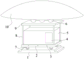
fig. 1 is a schematic overall structure diagram of the present invention;
FIG. 2 is a schematic front sectional view of the whole body of the present invention;
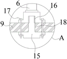
FIG. 3 is an enlarged schematic view of the structure at the position A of the present invention;
fig. 4 is a schematic view of the upper surface structure of the support plate of the present invention;
in the figure: 1. a base; 2. a support plate; 3. a bolt A; 4. adding an oil level; 5. a skid-mounted oil tank; 6. a vertical rod; 7. a hydraulic telescopic rod; 8. a support bar; 9. a transverse plate; 10. a ceiling; 11. a hydraulic cylinder; 12. vertical holes; 13. a card slot; 14. a baffle plate; 15. inserting plates; 16. a thread groove; 17. a bolt B; 18. and a through hole.
Detailed Description
The technical solutions in the embodiments of the present invention will be clearly and completely described below with reference to the drawings in the embodiments of the present invention, and it is obvious that the described embodiments are only some embodiments of the present invention, not all embodiments; based on the embodiments in the present invention, all other embodiments obtained by a person skilled in the art without creative work belong to the protection scope of the present invention.
In the first embodiment, the first step is,given by FIGS. 1-4The utility model relates to a sled dress formula filling station, the on-line screen storage device comprises a base 1, 1 inside hydraulic pressure that is provided with of baseThe hydraulic telescopic rod mechanism comprises a cylinder 11, wherein the inner side wall of the hydraulic cylinder 11 is slidably connected with one end of a hydraulic telescopic rod 7, the other end of the hydraulic telescopic rod 7 is fixedly connected with the outer wall of the bottom surface of a support plate 2, the upper surface of the support plate 2 is provided with a clamping groove 13, the inner side wall of the clamping groove 13 is connected with a skid-mounted oil tank 5 in an embedded manner, the outer wall of the opening end of the clamping groove 13 is provided with one end of a support rod 8, the other end of the support rod 8 is fixedly connected with the outer wall of the bottom surface of a transverse plate 9, the outer wall of the bottom surface of the transverse plate 9 is provided with a through hole 18, the inner side wall of the through hole 18 is inserted with an inserting plate 15, the outer side wall of the inserting plate 15 is in threaded connection with the inner side wall of a threaded groove 16, the threaded groove 16 is formed in the outer wall of the bottom surface of a vertical rod 6, the upper surface of the vertical rod 6 is fixedly connected with the outer wall of a ceiling 10, and the hydraulic telescopic rod 7 can be driven to vertically slide by switching on a power supply and controlling the operation of the hydraulic cylinder 11, and then can drive backup pad 2 vertical removal in vertical direction, just so make backup pad 2 break away from baffle 14 and carry out vertical lifting, the effectual vertical height who realizes sled dress formula tank 5 is adjustable.
Referring to fig. 1, 2 and 4, one end of a bolt A3 is inserted into the outer side wall of the support plate 2, the other end of the bolt A3 extends to the inside of the skid-mounted oil filling box 5, the outer side wall of the skid-mounted oil filling box 5 is provided with an oil filling level 4, and the support plate 2 and the skid-mounted oil filling box 5 can be detachably connected by rotating the bolt A3 along the outer side wall of the support plate 2 and extending to the inside of the skid-mounted oil filling box 5.
Referring to fig. 1 and 2, the outer wall of the bottom surface of the base 1 is provided with a plurality of vertical holes 12, and the base 1 can be detachably connected with the ground by matching fasteners along the vertical holes 12.
Referring to fig. 1 and 2, a baffle plate 14 is arranged on the upper surface of the base 1, and the baffle plate 14 is located in the middle of the hydraulic telescopic rod 7, so that the support plate 2 can be supported by the baffle plate 14 when the hydraulic cylinder 11 is not in operation, and the height of the support plate 2 is kept stable.
Referring to fig. 1 and 3, the one end that has bolt B17 is pegged graft to the montant 6 lateral wall, just the other end of bolt B17 runs through diaphragm 9 and extends to picture peg 15 bottom surface outer wall, thereby can carry out further detachable connection between montant 6 and the picture peg 15 through rotatory bolt B17, and it is convenient effectively to have realized that the protector of sled dress formula oil tank 5 dismantles and installs.
Referring to fig. 1 and 2, the signal input end of the hydraulic cylinder 11 is electrically connected with the signal output end of the external electric control cabinet, and the on-off and operation of the circuit of the hydraulic cylinder 11 can be controlled by switching on the power supply and controlling the external electric control cabinet, so that the control is convenient and fast, and the safety is excellent.
The working principle is as follows: during operation, firstly, the base 1 can be detachably connected with the ground by matching a fastener along the vertical hole 12, then the skid-mounted oil tank 5 is placed along the clamping groove 13, so that the skid-mounted oil tank 5 can be preliminarily embedded and connected with the supporting plate 2, then the supporting plate 2 can be detachably connected with the skid-mounted oil tank 5 by rotating the bolt A3 along the outer side wall of the supporting plate 2 and extending into the skid-mounted oil tank 5, then the vertical rod 6 is placed on the upper surface of the opening end of the vertical hole 12, then the inserting plate 15 is inserted into the through hole 18 and the inserting plate 15 is rotated along the thread groove 16, so that the inserting plate 15 and the vertical rod 6 can be preliminarily detachably connected, then the vertical rod 6 and the inserting plate 15 can be further detachably connected by rotating the bolt B17, and the dismounting and mounting convenience of the protecting device of the skid-mounted oil tank 5 are effectively realized, and adopt base 1, backup pad 2, bracing piece 8, also ensured sled dress formula oil tank 5 to protect safety and reliable under the three-dimensional double-deck protective action of diaphragm 9 and ceiling 10, thereby it can drive the vertical slip of hydraulic telescoping rod 7 to then operate through switch on and control pneumatic cylinder 11, and then can drive backup pad 2 vertical removal in vertical direction, just so also make backup pad 2 can break away from baffle 14 and carry out vertical lifting, the effectual vertical height that has realized sled dress formula oil tank 5 is adjustable.
It is noted that, herein, relational terms such as first and second, and the like may be used solely to distinguish one entity or action from another entity or action without necessarily requiring or implying any actual such relationship or order between such entities or actions. Also, the terms "comprises," "comprising," or any other variation thereof, are intended to cover a non-exclusive inclusion, such that a process, method, article, or apparatus that comprises a list of elements does not include only those elements but may include other elements not expressly listed or inherent to such process, method, article, or apparatus.
Although embodiments of the present invention have been shown and described, it will be appreciated by those skilled in the art that changes, modifications, substitutions and alterations can be made in these embodiments without departing from the principles and spirit of the invention, the scope of which is defined in the appended claims and their equivalents.
Claims (6)
1. The utility model provides a sled dress formula filling station, includes base (1), its characterized in that: the base (1) is internally provided with a hydraulic cylinder (11), the inner side wall of the hydraulic cylinder (11) is slidably connected with one end of a hydraulic telescopic rod (7), the other end of the hydraulic telescopic rod (7) is fixedly connected with the bottom outer wall of a supporting plate (2), the upper surface of the supporting plate (2) is provided with a clamping groove (13), the inner side wall of the clamping groove (13) is embedded and connected with a skid-mounted oil filling box (5), the outer wall of the opening end of the clamping groove (13) is provided with one end of a supporting rod (8), the other end of the supporting rod (8) is fixedly connected with the outer wall of the bottom surface of a transverse plate (9), the outer wall surface of the bottom surface of the transverse plate (9) is provided with a through hole (18), the inner side wall of the through hole (18) is spliced with an inserting plate (15), the outer side wall of the inserting plate (15) is in threaded connection with the inner side wall of a threaded groove (16), and the threaded groove (16) is arranged on the outer wall of the bottom surface of a vertical rod (6), the upper surface of the vertical rod (6) is fixedly connected with the outer wall of the bottom surface of the ceiling (10).
2. A skid mounted gasoline station as claimed in claim 1, wherein: the one end that has bolt A (3) is pegged graft to backup pad (2) lateral wall, and inside the other end of bolt A (3) extended to sled dress formula tank (5), sled dress formula tank (5) lateral wall is provided with oil level (4).
3. A skid mounted gasoline station as claimed in claim 1, wherein: the outer wall of the bottom surface of the base (1) is provided with a plurality of vertical holes (12), and the number of the vertical holes (12) is multiple.
4. A skid mounted gasoline station as claimed in claim 1, wherein: the upper surface of the base (1) is provided with a baffle (14), and the baffle (14) is positioned in the middle of the hydraulic telescopic rod (7).
5. A skid mounted gasoline station as claimed in claim 1, wherein: the outer side wall of the vertical rod (6) is inserted with one end of a bolt B (17), and the other end of the bolt B (17) penetrates through the transverse plate (9) and extends to the outer wall of the bottom surface of the inserting plate (15).
6. A skid mounted gasoline station as claimed in claim 1, wherein: and the signal input end of the hydraulic cylinder (11) is electrically connected with the signal output end of an external electric control cabinet.
Priority Applications (1)
| Application Number | Priority Date | Filing Date | Title |
|---|---|---|---|
| CN202120492530.8U CN214456805U (en) | 2021-03-08 | 2021-03-08 | Skid-mounted gas station |
Applications Claiming Priority (1)
| Application Number | Priority Date | Filing Date | Title |
|---|---|---|---|
| CN202120492530.8U CN214456805U (en) | 2021-03-08 | 2021-03-08 | Skid-mounted gas station |
Publications (1)
| Publication Number | Publication Date |
|---|---|
| CN214456805U true CN214456805U (en) | 2021-10-22 |
Family
ID=78153687
Family Applications (1)
| Application Number | Title | Priority Date | Filing Date |
|---|---|---|---|
| CN202120492530.8U Active CN214456805U (en) | 2021-03-08 | 2021-03-08 | Skid-mounted gas station |
Country Status (1)
| Country | Link |
|---|---|
| CN (1) | CN214456805U (en) |
-
2021
- 2021-03-08 CN CN202120492530.8U patent/CN214456805U/en active Active
Similar Documents
| Publication | Publication Date | Title |
|---|---|---|
| CN208476971U (en) | A kind of overhead type fault detector | |
| CN210774543U (en) | Vacuum pipeline air leakage detection device | |
| CN214456805U (en) | Skid-mounted gas station | |
| CN107242758B (en) | A kind of letter box arrangement equipped with illumination functions | |
| CN216642050U (en) | Underground water monitoring well head protection device | |
| CN106081199B (en) | A kind of minaudiere installing mechanism | |
| CN211821056U (en) | Pipeline bracket for petroleum drilling | |
| CN210073601U (en) | Jacking device for low-voltage sleeve of large transformer | |
| CN111959936A (en) | Transformer transfer device | |
| CN210771035U (en) | Manual fuel filling pump moving device | |
| CN211908031U (en) | High-voltage wire outlet cabinet convenient to overhaul | |
| CN205751770U (en) | Onboard integrated filtering oil for transformer device | |
| CN207490314U (en) | A kind of positioning device of the breaker of the high-voltage switch gear of mobile substation | |
| CN221744292U (en) | Mounting structure for small explosion-proof air conditioner | |
| CN219138395U (en) | High-pressure grouting machine capable of preventing grouting pipe from falling off | |
| CN204567818U (en) | A kind of side spare tire rack jacking system | |
| CN221039179U (en) | Main transformer detection equipment for booster station | |
| CN215662999U (en) | Automatic heat abstractor of new energy automobile charging pile | |
| CN219999778U (en) | Wisdom water affair operation management service platform | |
| CN214611559U (en) | Forced-ventilated type gas carbon dioxide generator | |
| CN202416833U (en) | Anticollision device for operation platform | |
| CN214745006U (en) | Intelligent gas pressure regulating cabinet | |
| CN210224622U (en) | Electric power cabinet | |
| CN217027413U (en) | Seepage drainage device for hydropower station | |
| CN207910262U (en) | A kind of architectural electricity power distribution cabinet |
Legal Events
| Date | Code | Title | Description |
|---|---|---|---|
| GR01 | Patent grant | ||
| GR01 | Patent grant |