CN214449587U - Mark device of beating based on electronic component - Google Patents
Mark device of beating based on electronic component Download PDFInfo
- Publication number
- CN214449587U CN214449587U CN202023297497.8U CN202023297497U CN214449587U CN 214449587 U CN214449587 U CN 214449587U CN 202023297497 U CN202023297497 U CN 202023297497U CN 214449587 U CN214449587 U CN 214449587U
- Authority
- CN
- China
- Prior art keywords
- side wall
- lead screw
- lateral wall
- workbench
- fixed
- Prior art date
- Legal status (The legal status is an assumption and is not a legal conclusion. Google has not performed a legal analysis and makes no representation as to the accuracy of the status listed.)
- Active
Links
Images


Abstract
The utility model discloses a belong to parts machining technical field, specifically be a beat mark device based on electronic component, comprises a workbench, the fixed bracing piece that is provided with the symmetry of lower lateral wall of workstation, the fixed connecting plate that is provided with in left end of lateral wall on the workstation, the spout has been seted up to the right side wall of connecting plate, the inside of spout vertically is provided with reciprocal lead screw, the upper end of reciprocal lead screw through first bearing with the last lateral wall of spout rotates to be connected, the lower extreme of reciprocal lead screw runs through the lower lateral wall of spout and the lateral wall of workstation and extends to the lower extreme of workstation, the fixed backup pad that is provided with of lateral wall of bracing piece, the fixed motor that is provided with in upper end of backup pad has effectively replaced the manual work in the past and has beaten the mark, and this device can beat the mark to electronic component fast automatic, has improved beat the efficiency of beating the mark greatly.
Description
Technical Field
The utility model relates to a parts machining technical field specifically is a beat mark device based on electronic component.
Background
In the in-process of parts machining production, often need beat the mark device and come to beat the sign indicating number to the part, the mark device is beaten the mark often through the upper and lower of manual regulation mark device to the part to current beating mark device in the in-process of using, and the part of manually taking installs the part, and this kind of mode is beaten mark efficiency and is lower, influences the progress of processing.
SUMMERY OF THE UTILITY MODEL
An object of the utility model is to provide a beat mark device based on electronic part to the mark device can only beat the mark through manual to the part is beaten to the current electronic part that proposes in solving above-mentioned background art, beats the lower problem of mark efficiency.
In order to achieve the above object, the utility model provides a following technical scheme: a marking device based on electronic parts comprises a workbench, wherein symmetrical supporting rods are fixedly arranged on the lower side wall of the workbench, a connecting plate is fixedly arranged at the left end of the upper side wall of the workbench, a chute is formed in the right side wall of the connecting plate, a reciprocating lead screw is longitudinally arranged in the chute, the upper end of the reciprocating lead screw is rotatably connected with the upper side wall of the chute through a first bearing, the lower end of the reciprocating lead screw penetrates through the lower side wall of the chute and the side wall of the workbench and extends to the lower end of the workbench, a supporting plate is fixedly arranged on the side wall of the supporting rod, a motor is fixedly arranged at the upper end of the supporting plate, the output end of the motor is fixedly connected with the lower end of the reciprocating lead screw, a first belt pulley is fixedly arranged at the lower end of the rod wall of the reciprocating lead screw, a sliding block is in threaded connection with the rod wall of the reciprocating lead screw, and a symmetrical mounting plate is fixedly arranged on the right side wall of the sliding block, two the fixed installation mechanism that is provided with the symmetry in inside of mounting panel, the lateral wall of mounting panel is provided with through installation mechanism is fixed beats the mark device, the right-hand member of workstation lateral wall rotates through the second bearing and is provided with the bull stick, the fixed carousel that is provided with in upper end of bull stick, the fixed second belt pulley that is provided with of lower extreme of bull stick, first belt pulley pass through the belt with rotate between the second belt pulley and connect, the fixed piece of placing that evenly arranges that is provided with of last lateral wall of carousel, the standing groove has been seted up to the last lateral wall of placing the piece, the internal contact of standing groove is provided with electronic component, the cavity of symmetry is seted up at the both ends of standing groove, the fixed fixture that is provided with in inside of cavity.
Preferably, installation mechanism includes two lead screws, two the lead screw all with the lateral wall threaded connection of mounting panel, two the one end of lead screw is the fixed rotatory piece that is provided with all, two the other end of lead screw is the fixed grip block that is provided with all, two the opposite side of grip block all with beat the lateral wall contact connection of mark device.
Preferably, fixture includes two springs, two the spring is all fixed to be set up in the inside of cavity, two the other end of spring is all fixed and is provided with the limiting plate, two the opposite side of limiting plate all with electronic component's lateral wall contact is connected.
Preferably, the turntable can rotate just for the time when the marking device reciprocates up and down once.
Preferably, the motor is an asynchronous speed reduction motor.
Compared with the prior art, the beneficial effects of the utility model are that:
through motor, reciprocal lead screw, slider, mounting panel, beat mark device, first belt pulley, second belt pulley, bull stick, carousel and place the common cooperation of piece, effectively replaced the manual work in the past and beaten the mark, this device can beat the mark to electronic component fast automatically, has improved the efficiency of beating the mark greatly.
Drawings
FIG. 1 is a schematic front view of the present invention;
FIG. 2 is a schematic top view of the structure of FIG. 1;
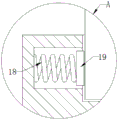
FIG. 3 is an enlarged schematic view of portion A of FIG. 1;
fig. 4 is an enlarged schematic structural view of a portion B in fig. 2.
In the figure: 1 workstation, 2 bracing pieces, 3 connecting plates, 4 reciprocating screw rods, 5 backup pads, 6 motors, 7 first belt pulleys, 8 sliders, 9 mounting plates, 10 marking devices, 11 rotating rods, 12 turntables, 13 placing blocks, 14 electronic parts, 15 screw rods, 16 rotating blocks, 17 clamping plates, 18 springs, 19 limiting plates and 20 second belt pulleys.
Detailed Description
The technical solutions in the embodiments of the present invention will be described clearly and completely with reference to the accompanying drawings in the embodiments of the present invention, and it is obvious that the described embodiments are only some embodiments of the present invention, not all embodiments. Based on the embodiments in the present invention, all other embodiments obtained by a person skilled in the art without creative work belong to the protection scope of the present invention.
In the description of the present invention, it is to be understood that the terms "upper", "lower", "front", "rear", "left", "right", "top", "bottom", "inner", "outer", and the like indicate orientations or positional relationships based on the orientations or positional relationships shown in the drawings, and are only for convenience of description and simplicity of description, and do not indicate or imply that the device or element being referred to must have a particular orientation, be constructed and operated in a particular orientation, and therefore, should not be construed as limiting the present invention.
Example (b):
referring to fig. 1-4, the present invention provides a technical solution: a marking device based on electronic parts comprises a workbench 1, symmetrical support rods 2 are fixedly arranged on the lower side wall of the workbench 1, a connecting plate 3 is fixedly arranged at the left end of the upper side wall of the workbench 1, a chute is formed in the right side wall of the connecting plate 3, a reciprocating lead screw 4 is longitudinally arranged in the chute, the upper end of the reciprocating lead screw 4 is rotatably connected with the upper side wall of the chute through a first bearing, the lower end of the reciprocating lead screw 4 penetrates through the lower side wall of the chute and the side wall of the workbench 1 and extends to the lower end of the workbench 1, a support plate 5 is fixedly arranged on the side wall of the support rod 2, a motor 6 is fixedly arranged at the upper end of the support plate 5, the output end of the motor 6 is fixedly connected with the lower end of the reciprocating lead screw 4, a first belt pulley 7 is fixedly arranged at the lower end of the rod wall of the reciprocating lead screw 4, a slide block 8 is in threaded connection with the rod wall of the reciprocating lead screw 4, and symmetrical mounting plates 9 are fixedly arranged on the right side wall of the slide block 8, the fixed installation mechanism that is provided with the symmetry in inside of two mounting panels 9, the lateral wall of mounting panel 9 is provided with marking device 10 through the installation mechanism is fixed, the right-hand member of 1 lateral wall of workstation rotates through the second bearing and is provided with bull stick 11, the fixed carousel 12 that is provided with in upper end of bull stick 11, the fixed second belt pulley 20 that is provided with of lower extreme of bull stick, first belt pulley 7 passes through the belt and rotates between the second belt pulley 20 to be connected, the fixed piece 13 of placing that evenly arranges that is provided with of last lateral wall of carousel 12, the standing groove has been seted up to the last lateral wall of placing piece 13, the internal contact of standing groove is provided with electronic component 14, the cavity of symmetry is seted up at the both ends of standing groove, the fixed fixture that is provided with in inside of cavity.
The installation mechanism comprises two lead screws 15, the two lead screws 15 are in threaded connection with the side wall of the installation plate 9, one ends of the two lead screws 15 are fixedly provided with rotating blocks 16, the other ends of the two lead screws 15 are fixedly provided with clamping plates 17, the other sides of the two clamping plates 17 are in contact connection with the side wall of the marking device 10, the marking device 10 is conveniently fixed inside the installation plate 9, and the installation and the disassembly are convenient.
Fixture includes two springs 18, and two springs 18 are all fixed to be set up in the inside of cavity, and two springs 18's the other end is all fixed and is provided with limiting plate 19, and two limiting plate 19's opposite side all is connected with electronic part 14's lateral wall contact, carries out the centre gripping to electronic part 14 and fixes, prevents to beat the target in-process, and electronic part 14 rocks, causes and beats the mark error.
When the marking device 10 reciprocates up and down once, the turntable 12 can just rotate for 90 degrees, so that the electronic part 14 can be marked continuously without manual operation, and the marking efficiency is greatly improved.
The motor 6 adopts an asynchronous speed reducing motor to control the speed of the whole marking process.
The working principle is as follows: when the marking device is used, an electronic part 14 is placed inside a placing block 13, a spring 18 pushes limiting plates 19 fixedly connected with side walls to move, the electronic part 14 is clamped and fixed by the two limiting plates 19, a rotating block 16 is rotated, the rotating block 16 drives a lead screw 15 fixedly connected with the side walls to rotate, the lead screw 15 drives a clamping plate 17 fixedly connected with the side walls to move, the marking device 10 is clamped and fixed, a motor 6 is started, the motor 6 drives a reciprocating lead screw 4 fixedly connected with the upper end to rotate, the reciprocating lead screw 4 drives a slide block 8 in threaded connection with a rod wall to move, the slide block 8 drives a marking device 10 fixedly connected with the side walls to mark the electronic part 14, the reciprocating lead screw 4 drives a first belt pulley 7 to rotate, the first belt pulley 7 drives a second belt pulley 20 to rotate through a belt, the second belt pulley 20 drives a rotating rod 11 to rotate, and the rotating rod 11 drives a rotating disc 12 fixedly connected with the upper end to rotate, when the marking device 10 reciprocates up and down once, the electronic part 14 just can rotate 90 degrees, and the high-efficiency marking is continuously carried out on the electronic part 14.
Having shown and described the basic principles and principal features of the invention and advantages thereof, it will be apparent to those skilled in the art that the invention is not limited to the details of the foregoing exemplary embodiments, but is capable of other specific forms without departing from the spirit or essential characteristics thereof; the present embodiments are therefore to be considered in all respects as illustrative and not restrictive, the scope of the invention being indicated by the appended claims rather than by the foregoing description, and all changes which come within the meaning and range of equivalency of the claims are therefore intended to be embraced therein, and any reference signs in the claims are not intended to be construed as limiting the claim concerned.
Although embodiments of the present invention have been shown and described, it will be appreciated by those skilled in the art that changes, modifications, substitutions and alterations can be made in these embodiments without departing from the principles and spirit of the invention, the scope of which is defined in the appended claims and their equivalents.
Claims (5)
1. A marking device based on electronic parts comprises a workbench (1) and is characterized in that symmetrical support rods (2) are fixedly arranged on the lower side wall of the workbench (1), a connecting plate (3) is fixedly arranged at the left end of the upper side wall of the workbench (1), a sliding groove is formed in the right side wall of the connecting plate (3), a reciprocating lead screw (4) is longitudinally arranged inside the sliding groove, the upper end of the reciprocating lead screw (4) is rotatably connected with the upper side wall of the sliding groove through a first bearing, the lower end of the reciprocating lead screw (4) penetrates through the lower side wall of the sliding groove and the side wall of the workbench (1) and extends to the lower end of the workbench (1), a support plate (5) is fixedly arranged on the side wall of the support rod (2), a motor (6) is fixedly arranged at the upper end of the support plate (5), and the output end of the motor (6) is fixedly connected with the lower end of the reciprocating lead screw (4), the lower end of the rod wall of the reciprocating screw rod (4) is fixedly provided with a first belt pulley (7), the rod wall of the reciprocating screw rod (4) is in threaded connection with a slider (8), the right side wall of the slider (8) is fixedly provided with a symmetrical mounting plate (9), two mounting mechanisms of symmetry are fixedly arranged inside the mounting plate (9), the side wall of the mounting plate (9) is fixedly provided with a marking device (10) through the mounting mechanism, the right end of the side wall of the workbench (1) is rotatably provided with a rotating rod (11) through a second bearing, the upper end of the rotating rod (11) is fixedly provided with a turntable (12), the lower end of the rotating rod is fixedly provided with a second belt pulley (20), the first belt pulley (7) is rotatably connected with the second belt pulley (20) through a belt, and the upper side wall of the turntable (12) is fixedly provided with placing blocks (13) which are uniformly arranged, the upper side wall of the placing block (13) is provided with a placing groove, electronic parts (14) are arranged in the placing groove in a contact mode, two ends of the placing groove are provided with symmetrical cavities, and a clamping mechanism is fixedly arranged in the cavities.
2. Marking device according to claim 1, characterized in that: installation mechanism includes two lead screws (15), two lead screw (15) all with the lateral wall threaded connection of mounting panel (9), two the one end of lead screw (15) is all fixed and is provided with rotatory piece (16), two the other end of lead screw (15) is all fixed and is provided with grip block (17), two the opposite side of grip block (17) all with the lateral wall contact of beating mark device (10) is connected.
3. Marking device according to claim 1, characterized in that: fixture includes two springs (18), two spring (18) are all fixed to be set up in the inside of cavity, two the other end of spring (18) is all fixed and is provided with limiting plate (19), two the opposite side of limiting plate (19) all with the lateral wall contact of electronic part (14) is connected.
4. Marking device according to claim 1, characterized in that: when the marking device (10) reciprocates up and down once, the rotary disc (12) can just rotate for 90 degrees.
5. Marking device according to claim 1, characterized in that: the motor (6) adopts an asynchronous speed reducing motor.
Priority Applications (1)
| Application Number | Priority Date | Filing Date | Title |
|---|---|---|---|
| CN202023297497.8U CN214449587U (en) | 2020-12-31 | 2020-12-31 | Mark device of beating based on electronic component |
Applications Claiming Priority (1)
| Application Number | Priority Date | Filing Date | Title |
|---|---|---|---|
| CN202023297497.8U CN214449587U (en) | 2020-12-31 | 2020-12-31 | Mark device of beating based on electronic component |
Publications (1)
| Publication Number | Publication Date |
|---|---|
| CN214449587U true CN214449587U (en) | 2021-10-22 |
Family
ID=78109201
Family Applications (1)
| Application Number | Title | Priority Date | Filing Date |
|---|---|---|---|
| CN202023297497.8U Active CN214449587U (en) | 2020-12-31 | 2020-12-31 | Mark device of beating based on electronic component |
Country Status (1)
| Country | Link |
|---|---|
| CN (1) | CN214449587U (en) |
-
2020
- 2020-12-31 CN CN202023297497.8U patent/CN214449587U/en active Active
Similar Documents
| Publication | Publication Date | Title |
|---|---|---|
| CN210387287U (en) | Special clamp for machining bent parts | |
| CN210967902U (en) | Special clamp for engraving and milling machine | |
| CN209812130U (en) | Clamp for steel pipe machining | |
| CN214309860U (en) | Hardness detection device for material science | |
| CN214449587U (en) | Mark device of beating based on electronic component | |
| CN219915720U (en) | Withstand voltage test fixture for circuit board | |
| CN212044298U (en) | Clamping equipment for machining guide pillar of forging and pressing machine | |
| CN211086062U (en) | Adjusting mechanism for glass visual inspection | |
| CN112238447A (en) | Industrial robot arm extension mechanism | |
| CN111037185A (en) | Automatic change door frame welding equipment | |
| CN215356420U (en) | High-precision steel structure section bar cutting device | |
| CN210201144U (en) | Servo rotary pin inserting device | |
| CN213319736U (en) | Production and processing metal jig for precision device | |
| CN211361429U (en) | Spare part adds clamping apparatus | |
| CN114441350A (en) | Motor housing hardness test equipment | |
| CN217072105U (en) | Metal jig for producing precision device | |
| CN210909044U (en) | Novel drilling machine overlength piece quick travel subassembly | |
| CN217747902U (en) | Positioning device for liquid crystal display dispensing device | |
| CN217237496U (en) | Glass pressure-resistant detection equipment | |
| CN218612772U (en) | Novel drilling and milling machine | |
| CN213439488U (en) | Fixed working table for maintaining industrial electronic meter | |
| CN212886220U (en) | Positioning platform of machining operation center | |
| CN214603576U (en) | Grinding device is used in drive chain processing | |
| CN217787299U (en) | Digital integrated circuit testing and processing device | |
| CN218363388U (en) | Clamping device for manufacturing mechanical electrical equipment |
Legal Events
| Date | Code | Title | Description |
|---|---|---|---|
| GR01 | Patent grant | ||
| GR01 | Patent grant |