CN214437447U - Flue gas purification device of flue gas desulfurization tower - Google Patents
Flue gas purification device of flue gas desulfurization tower Download PDFInfo
- Publication number
- CN214437447U CN214437447U CN202023317925.9U CN202023317925U CN214437447U CN 214437447 U CN214437447 U CN 214437447U CN 202023317925 U CN202023317925 U CN 202023317925U CN 214437447 U CN214437447 U CN 214437447U
- Authority
- CN
- China
- Prior art keywords
- flue gas
- filter screen
- box
- purification device
- desulfurization tower
- Prior art date
- Legal status (The legal status is an assumption and is not a legal conclusion. Google has not performed a legal analysis and makes no representation as to the accuracy of the status listed.)
- Active
Links
Images



Landscapes
- Treating Waste Gases (AREA)
Abstract
The utility model discloses a flue gas purification device of flue gas desulfurization tower, including box, dust screen, purifying box and header tank, the bottom fixedly connected with support column of box, and the bottom center department of box is provided with the bin outlet, the distribution connection all around of dust screen has the slider, and the outside of slider is provided with the spout, the right side below of box is provided with the water pump, and the left and right sides of water pump is connected with the water pipe to the below of water pipe is connected with the shower nozzle. This flue gas purification device of flue gas desulfurization tower is provided with the active carbon filter screen, second filter screen and purifying box, and at the in-process that uses, can carry out the intensive mixing reaction through the agitator to the flue gas through the purifying box to the purification efficiency of flue gas has been improved, and makes the gas after purifying further purify it when discharging through active carbon filter screen and second filter screen, and pollution abatement makes the purifying effect better, reduces the pollution of flue gas to air and environment.
Description
Technical Field
The utility model relates to a flue gas purification device technical field specifically is a flue gas purification device of flue gas desulfurization tower.
Background
The desulfurization tower is tower equipment for performing desulfurization treatment on industrial waste gas, and is widely applied to various large and medium thermal power plants, a large amount of dust and harmful gas can be generated in the starting process of an engine in the using process of a ship, and the harmful gas can be discharged after being purified by a purifying device so as to avoid air pollution, but the existing flue gas purifying device has certain problems in the using process;
the purification effect of current gas cleaning device to the flue gas is poor, because probably contain impurity can not be fine cleaing away in the flue gas, cause probably to cause secondary pollution at the in-process of purification, lead to having serious pollution to the air, and current dust screen is not convenient for install and dismantle, make the dust screen be not convenient for wash and lead to the dust screen to block up the flue gas discharge after being not convenient for purify, and current purifier does not possess the water cyclic utilization function, lead to extravagant a large amount of water resources.
We have therefore proposed a flue gas cleaning device for a flue gas desulfurization tower in order to solve the problems set forth above.
SUMMERY OF THE UTILITY MODEL
The utility model aims at providing a flue gas purification device of flue gas desulfurization tower to solve the problem that purifying effect is poor, the dust screen is not convenient for install and dismantle and do not possess the water cyclic utilization function on the existing market that above-mentioned background art provided.
In order to achieve the above object, the utility model provides a following technical scheme: a flue gas purification device of a flue gas desulfurization tower comprises a box body, a dust screen, a purification box and a water collection box, wherein the bottom of the box body is fixedly connected with a support column, the center of the bottom of the box body is provided with a discharge hole, the top of the box body is provided with an exhaust hole, an adsorption plate is arranged inside the exhaust hole, an air inlet is arranged at the upper left of the box body, a fan is arranged above the adsorption plate, the dust screen is arranged above the fan, slide blocks are distributed and connected around the dust screen, slide grooves are arranged outside the slide blocks, an active carbon filter screen is arranged inside the box body, a second filter screen is arranged below the active carbon filter screen, a connecting rod is arranged below the second filter screen, one side of the connecting rod is fixedly connected with the purification box, the bottom of the inner side of the purification box is provided with a micro motor, and a stirrer is connected above the micro motor, the through-hole has been seted up at the bottom and the top of purifying box, and the below of purifying box is provided with first filter screen to the below of first filter screen is provided with the header tank, the right side below of box is provided with the water pump, and the left and right sides of water pump is connected with the water pipe, and the below of water pipe is connected with the shower nozzle.
Preferably, the number of the support columns is 4, the support columns are designed to be T-shaped, and the support columns are perpendicular to the box body.
Preferably, the adsorption plate and the dust screen are designed into a disc structure, the outer diameters of the adsorption plate and the dust screen are equal to the inner diameter of the exhaust port, and the adsorption plate and the dust screen are parallel to each other.
Preferably, be sliding connection between slider and the spout, and slider and spout setting all have 4 to the external diameter of slider is less than the internal diameter of spout.
Preferably, the active carbon filter screen all is disc type structural design with the second filter screen and forms, and is parallel to each other between active carbon filter screen and the second filter screen to the external diameter of active carbon filter screen and second filter screen equals the internal diameter of box.
Preferably, the number of the connecting rods is 2, and the connecting rods are perpendicular to the purifying box.
Compared with the prior art, the beneficial effects of the utility model are that: a flue gas purification device of the flue gas desulfurization tower;
1. the activated carbon filter screen, the second filter screen and the purification box are arranged, so that in the using process, the purification box can fully stir and react the flue gas through the stirrer, the purification efficiency of the flue gas is improved, the purified gas is further purified when being discharged through the activated carbon filter screen and the second filter screen, the pollution is reduced, the purification effect is better, and the pollution of the flue gas to air and environment is reduced;
2. be provided with dust screen and header tank, at the in-process that uses, can carry out effectual filtration to the dust in the air through the dust screen, prevent that the dust from getting into the inside purification of the flue gas of being not convenient for of box, avoid the dust exhaust contaminated air in the flue gas simultaneously, be convenient for install and dismantle the dust screen through spout and slider simultaneously, make the dust screen be convenient for wash, avoid the dust screen to take place to block up, and can collect and cyclic utilization the water resource through the header tank, practiced thrift the water resource.
Drawings
FIG. 1 is a schematic view of the main sectional structure of the present invention;
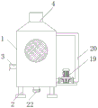
FIG. 2 is a schematic view of the structure of the present invention;
FIG. 3 is a schematic view of the cross-sectional structure of the purification box of the present invention;
fig. 4 is an enlarged schematic structural view of a portion a in fig. 1 according to the present invention.
In the figure: 1. a box body; 2. a support pillar; 3. an air inlet; 4. an exhaust port; 5. an adsorption plate; 6. a fan; 7. a dust screen; 8. a slider; 9. a chute; 10. an active carbon filter screen; 11. a second filter screen; 12. a connecting rod; 13. a purification box; 14. a micro motor; 15. a stirrer; 16. a through hole; 17. a first filter screen; 18. a water collection tank; 19. a water pump; 20. a water pipe; 21. a spray head; 22. a discharge outlet.
Detailed Description
The technical solutions in the embodiments of the present invention will be described clearly and completely with reference to the accompanying drawings in the embodiments of the present invention, and it is obvious that the described embodiments are only some embodiments of the present invention, not all embodiments. Based on the embodiments in the present invention, all other embodiments obtained by a person skilled in the art without creative work belong to the protection scope of the present invention.
Referring to fig. 1-4, the present invention provides a technical solution: a flue gas purification device of a flue gas desulfurization tower comprises a box body 1, a support column 2, a gas inlet 3, a gas outlet 4, an adsorption plate 5, a fan 6, a dustproof net 7, a slide block 8, a chute 9, an activated carbon filter screen 10, a second filter screen 11, a connecting rod 12, a purification box 13, a micro motor 14, a stirrer 15, a through hole 16, a first filter screen 17, a water collecting box 18, a water pump 19, a water pipe 20, a spray head 21 and a discharge port 22, wherein the bottom of the box body 1 is fixedly connected with the support column 2, the center of the bottom of the box body 1 is provided with the discharge port 22, the top of the box body 1 is provided with the gas outlet 4, the adsorption plate 5 is arranged inside the gas outlet 4, the gas inlet 3 is arranged at the upper left side of the box body 1, the fan 6 is arranged above the adsorption plate 5, the dustproof net 7 is arranged above the fan 6, the slide blocks 8 are distributed and connected around the dustproof net 7, and the chute 9 is arranged outside the slide block 8, the inside of box 1 is provided with activated carbon filter screen 10, and the below of activated carbon filter screen 10 is provided with second filter screen 11, and the below of second filter screen 11 is provided with connecting rod 12, one side fixedly connected with purifying box 13 of connecting rod 12, and the inboard bottom of purifying box 13 is provided with micro motor 14, and micro motor 14's top is connected with agitator 15, through-hole 16 has been seted up at the bottom and the top of purifying box 13, and the below of purifying box 13 is provided with first filter screen 17, and the below of first filter screen 17 is provided with header tank 18, the right side below of box 1 is provided with water pump 19, and the left and right sides of water pump 19 is connected with water pipe 20, and the below of water pipe 20 is connected with shower nozzle 21.
For sliding connection between slider 8 and the spout 9, and slider 8 and the setting of spout 9 all have 4 to the external diameter of slider 8 is less than the internal diameter of spout 9, and the design of above-mentioned structure makes 7 installation dismantlements of dust screen through slider 8 and spout 9, and the washing of 7 dust screens of being convenient for has strengthened the convenience of device.
Activated carbon filter screen 10 all is disc type structural design with second filter screen 11 and forms, and is parallel to each other between activated carbon filter screen 10 and the second filter screen 11 to the external diameter of activated carbon filter screen 10 and second filter screen 11 equals the internal diameter of box 1, and the design of above-mentioned structure is convenient for through activated carbon filter screen 10 and second filter screen 11 to the better more powerful purification of flue gas, has guaranteed the purifying effect of flue gas.
Connecting rod 12 is provided with 2, and mutually perpendicular between connecting rod 12 and the purifying box 13, and the design of above-mentioned structure for be connected between connecting rod 12 and the purifying box 13 more firm, guaranteed the steadiness of purifying box 13.
The working principle is as follows: when the flue gas purification device of the flue gas desulfurization tower is used, firstly, as shown in figures 1-4, the device is placed at a proper position and is stably placed through a support column 2 so as to be convenient to use, after the device is placed stably, flue gas to be purified enters the box body 1 through an air inlet 3, when the flue gas enters the box body 1, a water pump 19 is turned on, water reaches a spray head 21 from a water pipe 20 to spray the flue gas in the box body 1, meanwhile, in the spraying process, a part of the flue gas enters the purification box 13, a stirrer 15 rotates under the action of a micro motor 14, so that the flue gas is sufficiently purified, meanwhile, an active carbon filter screen 10 and a second filter screen 11 can adsorb and filter the flue gas, so that the purification effect of the flue gas is better, when the flue gas is discharged through an exhaust port 4, the adsorption plate 5 and a dust screen 7 at the exhaust port 4 are used for secondary filtration, make flue gas purification's effect more showing, thereby the shower nozzle 21 department filters the water that gets into header tank 18 through first filter screen 17 and collects the cyclic utilization of being convenient for simultaneously, the effectual water resource of having protected.
To thereby carry out a series of tasks, the contents of which are not described in detail in the present specification are prior art well known to those skilled in the art.
Although the present invention has been described in detail with reference to the foregoing embodiments, it will be apparent to those skilled in the art that modifications may be made to the embodiments or portions thereof without departing from the spirit and scope of the invention.
Claims (6)
1. The utility model provides a flue gas purification device of flue gas desulfurization tower, includes box (1), dust screen (7), purifying box (13) and header tank (18), its characterized in that: the bottom of the box body (1) is fixedly connected with a support column (2), a discharge hole (22) is formed in the center of the bottom of the box body (1), an exhaust port (4) is formed in the top of the box body (1), an adsorption plate (5) is arranged inside the exhaust port (4), an air inlet (3) is formed in the upper left side of the box body (1), a fan (6) is arranged above the adsorption plate (5), a dust screen (7) is arranged above the fan (6), sliders (8) are distributed and connected around the dust screen (7), a sliding groove (9) is formed in the outer side of each slider (8), an active carbon filter screen (10) is arranged inside the box body (1), a second filter screen (11) is arranged below the active carbon filter screen (10), a connecting rod (12) is arranged below the second filter screen (11), a purification box (13) is fixedly connected to one side of the connecting rod (12), and the inboard bottom of purifying box (13) is provided with micro motor (14) to the top of micro motor (14) is connected with agitator (15), through-hole (16) have been seted up at the bottom and the top of purifying box (13), and the below of purifying box (13) is provided with first filter screen (17), and the below of first filter screen (17) is provided with header tank (18), the right side below of box (1) is provided with water pump (19), and the left and right sides of water pump (19) is connected with water pipe (20) to the below of water pipe (20) is connected with shower nozzle (21).
2. The flue gas purification device of a flue gas desulfurization tower according to claim 1, characterized in that: the support columns (2) are 4, the support columns (2) are designed to be T-shaped, and the support columns (2) are perpendicular to the box body (1).
3. The flue gas purification device of a flue gas desulfurization tower according to claim 1, characterized in that: adsorption plate (5) and dust screen (7) all are the design of disc type structure and form, and the external diameter of adsorption plate (5) and dust screen (7) equals the internal diameter of gas vent (4) to be parallel to each other between adsorption plate (5) and dust screen (7).
4. The flue gas purification device of a flue gas desulfurization tower according to claim 1, characterized in that: be sliding connection between slider (8) and spout (9), and slider (8) and spout (9) set up and all have 4 to the external diameter of slider (8) is less than the internal diameter of spout (9).
5. The flue gas purification device of a flue gas desulfurization tower according to claim 1, characterized in that: activated carbon filter screen (10) all are disc type structural design with second filter screen (11) and form, and are parallel to each other between activated carbon filter screen (10) and second filter screen (11) to the external diameter of activated carbon filter screen (10) and second filter screen (11) equals the internal diameter of box (1).
6. The flue gas purification device of a flue gas desulfurization tower according to claim 1, characterized in that: the number of the connecting rods (12) is 2, and the connecting rods (12) are perpendicular to the purifying box (13).
Priority Applications (1)
| Application Number | Priority Date | Filing Date | Title |
|---|---|---|---|
| CN202023317925.9U CN214437447U (en) | 2020-12-31 | 2020-12-31 | Flue gas purification device of flue gas desulfurization tower |
Applications Claiming Priority (1)
| Application Number | Priority Date | Filing Date | Title |
|---|---|---|---|
| CN202023317925.9U CN214437447U (en) | 2020-12-31 | 2020-12-31 | Flue gas purification device of flue gas desulfurization tower |
Publications (1)
| Publication Number | Publication Date |
|---|---|
| CN214437447U true CN214437447U (en) | 2021-10-22 |
Family
ID=78109454
Family Applications (1)
| Application Number | Title | Priority Date | Filing Date |
|---|---|---|---|
| CN202023317925.9U Active CN214437447U (en) | 2020-12-31 | 2020-12-31 | Flue gas purification device of flue gas desulfurization tower |
Country Status (1)
| Country | Link |
|---|---|
| CN (1) | CN214437447U (en) |
Cited By (2)
| Publication number | Priority date | Publication date | Assignee | Title |
|---|---|---|---|---|
| CN114053855A (en) * | 2021-11-19 | 2022-02-18 | 东台宣龙防腐管道设备有限公司 | Powerful desulfurization and denitrification labyrinth purification module |
| CN114870516A (en) * | 2022-05-05 | 2022-08-09 | 上海京海(安徽)化工有限公司 | Insoluble sulfur tail gas recovery and storage pilot plant and implementation method thereof |
-
2020
- 2020-12-31 CN CN202023317925.9U patent/CN214437447U/en active Active
Cited By (2)
| Publication number | Priority date | Publication date | Assignee | Title |
|---|---|---|---|---|
| CN114053855A (en) * | 2021-11-19 | 2022-02-18 | 东台宣龙防腐管道设备有限公司 | Powerful desulfurization and denitrification labyrinth purification module |
| CN114870516A (en) * | 2022-05-05 | 2022-08-09 | 上海京海(安徽)化工有限公司 | Insoluble sulfur tail gas recovery and storage pilot plant and implementation method thereof |
Similar Documents
| Publication | Publication Date | Title |
|---|---|---|
| CN211864361U (en) | Spraying equipment for waste gas treatment | |
| CN214437447U (en) | Flue gas purification device of flue gas desulfurization tower | |
| CN201988299U (en) | Waste gas purifying device | |
| CN201006047Y (en) | Multifunctional cyclone type plasma air-treatment machine | |
| CN212881651U (en) | Be applied to thermoelectric buggy dust collector of clean high-efficient firepower | |
| CN2386872Y (en) | Pneumatic desulfurization dust collector | |
| CN203525525U (en) | Electric-bag combined dust remover | |
| CN216856271U (en) | Acid-base waste gas treatment tower | |
| CN214345553U (en) | Industrial waste gas treatment device | |
| CN214972563U (en) | Novel environmental protection removes dust device | |
| CN212523605U (en) | Injection type low-temperature plasma integrated waste gas treatment equipment | |
| CN108619841A (en) | A kind of second-hand flue gas circulating purifying device in interior | |
| CN214182368U (en) | Three-dimensional multistage high-efficient dust collector | |
| CN210522152U (en) | Air filter device | |
| CN209771697U (en) | Flue gas dust remover with multi-stage filtration function | |
| CN206911058U (en) | A kind of equipment for treating industrial waste gas using novel energy | |
| CN214051088U (en) | High efficiency flue gas denitration device | |
| CN2555935Y (en) | Composite oil fume purifier | |
| CN212855094U (en) | Board-like cleaning equipment of flue gas | |
| CN210674652U (en) | Baffle plate filtering device | |
| CN217220905U (en) | Red mud is used for desulfurization dust collector of thermoelectric flue gas | |
| CN221536022U (en) | Industrial waste gas desulfurization denitration dust collecting equipment | |
| CN204848475U (en) | Industrial waste water purifier | |
| CN215388362U (en) | Boiler waste gas purification treatment device | |
| CN214764518U (en) | High-efficient clarification plant of environment-friendly industrial waste gas |
Legal Events
| Date | Code | Title | Description |
|---|---|---|---|
| GR01 | Patent grant | ||
| GR01 | Patent grant |