CN214429018U - Airtight high-low voltage power distribution cabinet that many places were suitable for - Google Patents
Airtight high-low voltage power distribution cabinet that many places were suitable for Download PDFInfo
- Publication number
- CN214429018U CN214429018U CN202022320742.6U CN202022320742U CN214429018U CN 214429018 U CN214429018 U CN 214429018U CN 202022320742 U CN202022320742 U CN 202022320742U CN 214429018 U CN214429018 U CN 214429018U
- Authority
- CN
- China
- Prior art keywords
- power distribution
- distribution cabinet
- mounting bracket
- low voltage
- voltage power
- Prior art date
- Legal status (The legal status is an assumption and is not a legal conclusion. Google has not performed a legal analysis and makes no representation as to the accuracy of the status listed.)
- Active
Links
Images


Abstract
The utility model discloses a multi-location applicable closed high-low voltage power distribution cabinet, which comprises a power distribution cabinet main body, wherein the bottom of the power distribution cabinet main body is provided with a bottom bin, a servo motor is arranged at the middle position of the bottom in the bottom bin, the output end of the servo motor is provided with a double-groove belt pulley, threaded rods are arranged at the middle positions of the top and the two sides of the inner bottom in the power distribution cabinet main body, and an internal thread sleeve block is arranged outside the threaded rods; the utility model discloses a mutually supporting between first mounting bracket, spring, pull rod, second mounting bracket and the splint, can carry out the centre gripping to the wire and fix, can prevent that wire and the device internal component from taking place to drop, be provided with the second mounting bracket of multiunit on the first mounting bracket simultaneously to carry out categorised winding displacement to the multiunit wire, also be convenient for when improving the regularity the later stage overhaul and seek.
Description
Technical Field
The utility model relates to a high-low voltage distribution cabinet technical field specifically is an airtight type high-low voltage distribution cabinet that many places are suitable for.
Background
The high-low voltage power distribution cabinet is power distribution equipment for distributing, controlling, metering and connecting cables in a power supply system, a common power supply station and a substation use high-voltage switch cabinets, then are led out to the low-voltage power distribution cabinet through the voltage reduction low-voltage side of a transformer, and the low-voltage power distribution cabinet goes to each power distribution panel, a control box and a switch box, and protection devices such as switches, circuit breakers, fuses, buttons, indicator lamps, instruments, wires and the like are assembled into a whole to form the equipment of the power distribution device which meets the design functional requirements;
the existing low-voltage power distribution cabinet has the following defects in the actual use process: 1. most of the existing low-voltage power distribution cabinets are inconvenient to move, so that the applicability is poor; 2. the existing low-voltage power distribution cabinet is mostly fixed by bolts when internal elements are installed, so that the installation is complicated, time-consuming and labor-consuming; 3. high-low voltage distribution cabinet can mostly use the wire of multiunit when using, and current low-voltage distribution cabinet mostly does not arrange the wire in order, leads to walking the line more in disorder, and then seeks when influencing later stage and overhauing.
SUMMERY OF THE UTILITY MODEL
An object of the utility model is to provide an airtight type high-low voltage distribution cabinet that many places were suitable for to solve the problem that proposes in the above-mentioned background art.
In order to achieve the above object, the utility model provides a following technical scheme: a closed high-low voltage power distribution cabinet applicable to multiple places comprises a power distribution cabinet main body, wherein a bottom bin is arranged at the bottom of the power distribution cabinet main body, a servo motor is arranged at the middle position of the bottom in the bottom bin, a double-groove belt pulley is arranged at the output end of the servo motor, threaded rods are arranged at the middle positions of the top and the two sides of the bottom in the power distribution cabinet main body, inner thread sleeve blocks are arranged on the outer sides of the threaded rods, a connecting plate is arranged on one side, close to each other, of the two inner thread sleeve blocks, a mounting seat is arranged at the bottom of the connecting plate and extends to the outside of the bottom bin, a belt pulley is arranged at one end of the outer side of each threaded rod, belts are arranged on the outer sides of the belt pulleys and the double-groove belt pulley, multiple groups of limiting plates are uniformly arranged at one end inside the power distribution cabinet main body, multiple groups of limiting grooves are uniformly arranged at the top of one end of the limiting plates, the inside of spacing groove is provided with the stopper, the one end that the spacing groove was kept away from to the stopper is provided with the mounting panel, the one end that the limiting plate was kept away from to the inside both sides of switch board main part articulates there is fixed subassembly, the top of switch board main part one end one side is provided with control panel, control panel passes through the wire and is connected with the servo motor electricity.
Preferably, fixed subassembly includes first mounting bracket, spring, pull rod, second mounting bracket and splint, the one end that the limiting plate was kept away from to first mounting bracket position in the inside both sides of switch board main part, the inboard both sides of first mounting bracket evenly are provided with multiunit second mounting bracket, the intermediate position department at second mounting bracket top is provided with the pull rod, pull rod one end all is provided with splint with the inboard bottom of second mounting bracket, the one end that the pull rod outside is close to splint is provided with the spring.
Preferably, the four corners of the bottom of the mounting seat are provided with universal wheels, and the universal wheels are provided with braking devices.
Preferably, a motor protection cover is arranged on the outer side of the servo motor.
Preferably, the limiting groove and the limiting block are both formed by T-shaped structures.
Preferably, the four corners of the bottom bin are provided with supporting legs, and the bottoms of the supporting legs are provided with non-slip mats.
Preferably, one side of one end of the power distribution cabinet main body is hinged with a bin door, and a pull ring is arranged in the middle of one side of one end of the bin door.
Compared with the prior art, the beneficial effects of the utility model are that: the closed high-low voltage power distribution cabinet is suitable for multiple places;
1. the first mounting frame, the spring, the pull rod, the second mounting frame and the clamping plate are matched with each other, so that the wires can be clamped and fixed, the wires can be prevented from falling off from internal elements of the device, and meanwhile, the first mounting frame is provided with a plurality of groups of second mounting frames, so that the wires are classified and arranged, the uniformity is improved, and the later-stage overhaul and search are facilitated;
2. the device can be quickly and conveniently moved to a designated place through the arrangement of the universal wheels, and after the device is moved, the universal wheels can be conveniently retracted through the mutual matching of the servo motor, the belt, the double-groove belt pulley, the mounting seat, the connecting plate, the internal thread sleeve block, the belt pulley and the threaded rod, so that the stability of the device when the device is placed is improved, and the practicability of the device is further improved;
3. through the mutual cooperation between limiting plate, spacing groove, stopper and the mounting panel, be convenient for carry out quick installation to the mounting panel to the convenience is installed fast and is dismantled the device component, and simple structure, convenient operation labour saving and time saving.
Drawings
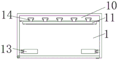
Fig. 1 is a front sectional view of the present invention;
FIG. 2 is a front view of the present invention;
fig. 3 is a top cross-sectional view of the present invention;
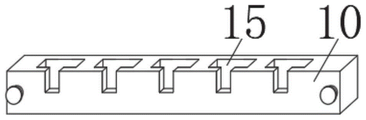
fig. 4 is a perspective view of the limiting plate of the present invention;
fig. 5 is a front cross-sectional view of a first mounting bracket of the present invention;
fig. 6 is an enlarged view of a portion a of fig. 1 according to the present invention.
In the figure: 1. a power distribution cabinet main body; 2. a belt pulley; 3. a threaded rod; 4. a bottom bin; 5. a mounting seat; 6. A connecting plate; 7. a universal wheel; 8. an internal thread sleeve block; 9. a servo motor; 10. a limiting plate; 11. mounting a plate; 12. a control panel; 13. a first mounting bracket; 14. a limiting block; 15. a limiting groove; 16. a spring; 17. a pull rod; 18. a second mounting bracket; 19. a splint; 20. a belt; 21. a double grooved pulley.
Detailed Description
The technical solutions in the embodiments of the present invention will be described clearly and completely with reference to the accompanying drawings in the embodiments of the present invention, and it is obvious that the described embodiments are only some embodiments of the present invention, not all embodiments. Based on the embodiments in the present invention, all other embodiments obtained by a person skilled in the art without creative work belong to the protection scope of the present invention.
Referring to fig. 1-6, the present invention provides an embodiment: a closed high-low voltage power distribution cabinet suitable for multiple places comprises a power distribution cabinet main body 1, a bottom bin 4 is arranged at the bottom of the power distribution cabinet main body 1, a servo motor 9 is arranged at the middle position of the bottom in the bottom bin 4, a double-groove belt pulley 21 is arranged at the output end of the servo motor 9, threaded rods 3 are arranged at the middle positions of the top and the two sides of the inner bottom in the power distribution cabinet main body 1, inner thread sleeve blocks 8 are arranged on the outer sides of the threaded rods 3, a connecting plate 6 is arranged at one side, close to each other, of the two groups of inner thread sleeve blocks 8, a mounting seat 5 is arranged at the bottom of the connecting plate 6 and is convenient to mount, the mounting seat 5 extends to the outer part of the bottom bin 4, a belt pulley 2 is arranged at one end of the outer side of each threaded rod 3, belts 20 are arranged on the outer sides of the belt pulley 2 and the double-groove belt pulley 21, a plurality of limiting plates 10 are uniformly arranged at one end of the power distribution cabinet main body 1, a plurality of limiting plates 15 are uniformly arranged at the top of one end of each limiting plate 10, play limiting displacement, the inside of spacing groove 15 is provided with stopper 14, and the one end that limiting groove 15 was kept away from to stopper 14 is provided with mounting panel 11, and the one end that limiting plate 10 was kept away from to 1 inside both sides of switch board main part articulates there is fixed subassembly, and the top of 1 one end one side of switch board main part is provided with control panel 12, and control panel 12 passes through the wire and is connected with servo motor 9 electricity.
In the implementation, the fixing component comprises a first mounting rack 13, springs 16, pull rods 17, second mounting racks 18 and clamping plates 19, the first mounting rack 13 is positioned at one end of two sides of the inside of the power distribution cabinet main body 1, which is far away from the limiting plate 10, multiple groups of second mounting racks 18 are uniformly arranged at two sides of the inner side of the first mounting rack 13, which is convenient to mount, the pull rods 17 are arranged at the middle positions of the tops of the second mounting racks 18, the clamping plates 19 are arranged at one ends of the pull rods 17 and the bottoms of the inner sides of the second mounting racks 18, the springs 16 are arranged at one ends, which are close to the clamping plates 19, of the outer sides of the pull rods 17, the universal wheels 7 are arranged at four corners of the bottom of the mounting seat 5, which are convenient to move, the braking devices are arranged on the universal wheels 7, the motor protective covers are arranged at the outer sides of the servo motors 9, the limiting grooves 15 and the limiting blocks 14 are all formed by T-shaped structures, supporting legs are arranged at four corners of the bottom bin 4, which play a supporting role, and the bottom of supporting leg is provided with the slipmat, increases the friction, and one side of 1 one end of switch board main part articulates there is the door, and the intermediate position department of door one end one side is provided with the pull ring, is convenient for open the door.
The working principle is as follows: the electric parts of the device are all powered by an external power supply, and the mounting plate 11 is convenient to mount quickly through the mutual matching between the limiting groove 15 on the limiting plate 10 and the limiting block 14 on the mounting plate 11, so that the elements of the device are convenient to mount and dismount quickly, and the device is simple in structure and convenient to operate, time-saving and labor-saving;
when the device is used, a plurality of groups of wires can be connected, the spring 16 is driven to compress by pulling the pull rod 17, then the wires are placed between the two groups of clamping plates 19, then the pull rod 17 is loosened, the clamping plates 19 are driven by the resilience force of the spring 16 to clamp and fix the wires, the wires can be prevented from falling off from internal elements of the device, meanwhile, a plurality of groups of second mounting frames 18 are arranged on the first mounting frame 13, so that the wires are classified and arranged, the uniformity is improved, and meanwhile, later-stage maintenance and searching are facilitated;
when the device need remove, start servo motor 9 through control panel 12, then through double flute belt pulley 21, mutually support between belt 20 and the belt pulley 2, can synchronous drive two sets of threaded rods 3 and rotate, thereby it removes to drive internal thread cover 8, and then make mount pad 5 shift out the inside of bottom storehouse 4, then can be fast convenient remove the device to appointed place through universal wheel 7, and can regain the bottom storehouse 4 with mount pad 5 after removing finishing in, improve the stability when the device is placed, further improvement the device's practicality.
It is obvious to a person skilled in the art that the invention is not restricted to details of the above-described exemplary embodiments, but that it can be implemented in other specific forms without departing from the spirit or essential characteristics of the invention. The present embodiments are therefore to be considered in all respects as illustrative and not restrictive, the scope of the invention being indicated by the appended claims rather than by the foregoing description, and all changes which come within the meaning and range of equivalency of the claims are therefore intended to be embraced therein. Any reference sign in a claim should not be construed as limiting the claim concerned.
In the description of the present invention, "a plurality" means two or more unless otherwise specified; the terms "upper", "lower", "left", "right", "inner", "outer", "front", "rear", "head", "tail", and the like indicate orientations or positional relationships based on the orientations or positional relationships shown in the drawings, and are merely for convenience of description and simplicity of description, and do not indicate or imply that the device or element being referred to must have a particular orientation, be constructed and operated in a particular orientation, and thus, should not be construed as limiting the present invention. Furthermore, the terms "first," "second," "third," and the like are used for descriptive purposes only and are not to be construed as indicating or implying relative importance.
In the description of the present invention, it is to be noted that, unless otherwise explicitly specified or limited, the terms "connected" and "connected" are to be interpreted broadly, and may be, for example, fixedly connected, detachably connected, or integrally connected; can be mechanically or electrically connected; may be directly connected or indirectly connected through an intermediate. The specific meaning of the above terms in the present invention can be understood in specific cases to those skilled in the art.
Claims (7)
1. The utility model provides an airtight type high-low voltage power distribution cabinet that many places were suitable for, includes switch board main part (1), its characterized in that: the bottom of the power distribution cabinet main body (1) is provided with a bottom bin (4), the middle position of the bottom in the bottom bin (4) is provided with a servo motor (9), the output end of the servo motor (9) is provided with a double-groove belt pulley (21), the middle position of the top and the two sides of the bottom in the power distribution cabinet main body (1) is provided with a threaded rod (3), the outer side of the threaded rod (3) is provided with an internal thread sleeve block (8), two groups of internal thread sleeve blocks (8) are provided with a connecting plate (6) at one side close to each other, the bottom of the connecting plate (6) is provided with a mounting seat (5), the mounting seat (5) extends to the outer part of the bottom bin (4), one end of the outer side of the threaded rod (3) is provided with a belt pulley (2), the outer sides of the belt pulley (2) and the double-groove belt pulley (21) are provided with belts (20), one end of the inner part of the power distribution cabinet main body (1) is uniformly provided with a plurality of groups of limiting plates (10), the top of limiting plate (10) one end evenly is provided with multiunit spacing groove (15), the inside of spacing groove (15) is provided with stopper (14), the one end that spacing groove (15) were kept away from in stopper (14) is provided with mounting panel (11), the one end that limiting plate (10) were kept away from to the inside both sides of switch board main part (1) articulates there is fixed subassembly, the top of switch board main part (1) one end one side is provided with control panel (12), control panel (12) are connected with servo motor (9) electricity through the wire.
2. The multi-site applicable closed high-low voltage power distribution cabinet according to claim 1, characterized in that: fixed subassembly includes first mounting bracket (13), spring (16), pull rod (17), second mounting bracket (18) and splint (19), limiting plate (10) was kept away from to first mounting bracket (13) position in switch board main part (1) inside both sides one end, the both sides of first mounting bracket (13) inboard evenly are provided with multiunit second mounting bracket (18), the intermediate position department at second mounting bracket (18) top is provided with pull rod (17), pull rod (17) one end all is provided with splint (19) with the inboard bottom of second mounting bracket (18), the one end that is close to splint (19) in the pull rod (17) outside is provided with spring (16).
3. The multi-site applicable closed high-low voltage power distribution cabinet according to claim 1, characterized in that: the four corners of the bottom of the mounting seat (5) are provided with universal wheels (7), and the universal wheels (7) are provided with braking devices.
4. The multi-site applicable closed high-low voltage power distribution cabinet according to claim 1, characterized in that: and a motor protective cover is arranged on the outer side of the servo motor (9).
5. The multi-site applicable closed high-low voltage power distribution cabinet according to claim 1, characterized in that: the limiting groove (15) and the limiting block (14) are both formed by T-shaped structures.
6. The multi-site applicable closed high-low voltage power distribution cabinet according to claim 1, characterized in that: the four corners of the bottom bin (4) are provided with supporting legs, and the bottoms of the supporting legs are provided with non-slip mats.
7. The multi-site applicable closed high-low voltage power distribution cabinet according to claim 1, characterized in that: one side of one end of the power distribution cabinet main body (1) is hinged with a bin door, and a pull ring is arranged in the middle of one side of one end of the bin door.
Priority Applications (1)
| Application Number | Priority Date | Filing Date | Title |
|---|---|---|---|
| CN202022320742.6U CN214429018U (en) | 2020-10-16 | 2020-10-16 | Airtight high-low voltage power distribution cabinet that many places were suitable for |
Applications Claiming Priority (1)
| Application Number | Priority Date | Filing Date | Title |
|---|---|---|---|
| CN202022320742.6U CN214429018U (en) | 2020-10-16 | 2020-10-16 | Airtight high-low voltage power distribution cabinet that many places were suitable for |
Publications (1)
| Publication Number | Publication Date |
|---|---|
| CN214429018U true CN214429018U (en) | 2021-10-19 |
Family
ID=78059212
Family Applications (1)
| Application Number | Title | Priority Date | Filing Date |
|---|---|---|---|
| CN202022320742.6U Active CN214429018U (en) | 2020-10-16 | 2020-10-16 | Airtight high-low voltage power distribution cabinet that many places were suitable for |
Country Status (1)
| Country | Link |
|---|---|
| CN (1) | CN214429018U (en) |
-
2020
- 2020-10-16 CN CN202022320742.6U patent/CN214429018U/en active Active
Similar Documents
| Publication | Publication Date | Title |
|---|---|---|
| CN112467553B (en) | Energy-saving flame retardant type high-low voltage switch cabinet | |
| CN214429018U (en) | Airtight high-low voltage power distribution cabinet that many places were suitable for | |
| CN210517402U (en) | High-low voltage switch cabinet convenient to installation wiring | |
| CN209881140U (en) | High-voltage switch cabinet | |
| CN214850055U (en) | Movable low-voltage switch cabinet | |
| CN214281575U (en) | Terminal clustering ultra-high mobility broadband communication device | |
| CN211480510U (en) | Wire fixing device of electric power distribution cabinet | |
| CN212875128U (en) | Low-voltage draw-out type switch cabinet | |
| CN212110916U (en) | High-low voltage switch cabinet testing device | |
| CN212162458U (en) | High-low voltage power distribution cabinet of convenient maintenance | |
| CN211949918U (en) | Combined electrical apparatus overhauls operation security fence | |
| CN209782175U (en) | Computer network strutting arrangement | |
| CN213460628U (en) | Low-voltage switch cabinet with cable capable of being connected with upper layer and lower layer in penetrating manner | |
| CN214478467U (en) | Intelligent wire arranging device for switch cabinet | |
| CN219106759U (en) | Prefabricated cabin switch cabinet base cable guiding device | |
| CN211981307U (en) | Power distribution cabinet with strong heat dissipation structure | |
| CN219498511U (en) | Switch cabinet wire arrangement structure | |
| CN220290584U (en) | Whole set distribution transformer rack | |
| CN217215578U (en) | Transformer substation is with integrative cabinet of measurement burden accuse | |
| CN212587913U (en) | Power distribution equipment for central machine room | |
| CN215497707U (en) | High-low voltage power distribution cabinet convenient to inside winding displacement | |
| CN220830218U (en) | Combined high-low voltage power distribution cabinet | |
| CN213402177U (en) | Drawer type power distribution cabinet | |
| CN219476437U (en) | Inductance transformer | |
| CN214044355U (en) | Electrical engineering distribution circuit breaker |
Legal Events
| Date | Code | Title | Description |
|---|---|---|---|
| GR01 | Patent grant | ||
| GR01 | Patent grant |