CN214399086U - Paper feeding mechanism of printer - Google Patents
Paper feeding mechanism of printer Download PDFInfo
- Publication number
- CN214399086U CN214399086U CN202120614158.3U CN202120614158U CN214399086U CN 214399086 U CN214399086 U CN 214399086U CN 202120614158 U CN202120614158 U CN 202120614158U CN 214399086 U CN214399086 U CN 214399086U
- Authority
- CN
- China
- Prior art keywords
- driving
- sliding
- plate
- cardboard
- screw rod
- Prior art date
- Legal status (The legal status is an assumption and is not a legal conclusion. Google has not performed a legal analysis and makes no representation as to the accuracy of the status listed.)
- Active
Links
Images


Abstract
The utility model relates to a printing machine paper feeding mechanism, it includes the base and sets up the guide mechanism of form advancing on the base, be equipped with the support on the base, it is connected with two slides to slide along the Y axle direction on the support, it is connected with two sucking discs to slide along the X axle direction on the slide, be equipped with power component one on the slide, be equipped with the lift piece that is used for driving the vertical reciprocating motion of sucking disc on the slide, be equipped with on the support and be used for power component two, the support is located and is equipped with the bearing subassembly that is used for accepting the cardboard border on the lateral wall of cardboard transmission direction both sides, be equipped with the slip subassembly that is used for driving the support to slide along cardboard transmission direction on the base. This application utilizes the cooperation of power component two and power component one for distance and the size adaptation of cardboard between the sucking disc, thereby reduce the cardboard border and take place the degree of collapsing under the action of gravity, and utilize the bearing subassembly to accept the cardboard border, further reduce the cardboard border and take place the possibility of collapsing under the action of gravity, thereby stability when promoting the cardboard material loading.
Description
Technical Field
The application relates to the technical field of printing machines, in particular to a paper feeding mechanism of a printing machine.
Background
The printing machine is generally composed of mechanisms for loading, inking, stamping and paper feeding, when printing, the characters and images to be printed are made into printing plate, then the printing plate is loaded on the printing machine, then the ink is coated on the position of the printing plate with characters and images by manpower or printing machine, the paper is fed to the paper feeding delivery port of the printing machine by paper feeding device, the paper is fed into the printing machine and transferred so as to copy the same printed matter as the printing plate.
The Chinese utility model with the authorization notice number of CN210973122U discloses a paper feeding and feeding device of a green paperboard printing machine, which comprises a base, wherein the base is provided with a rack, a paperboard storage box and a paper feeding and guiding mechanism, the rack is positioned above the paperboard storage box, the rack is provided with a paperboard adsorption mechanism, the paperboard adsorption mechanism comprises a sucker, a transverse lead screw, a nut base, a motor II, a hydraulic rod and a supporting plate, the sucker is arranged on the bottom wall of the supporting plate, and the paper feeding and guiding mechanism comprises a motor I, a first guiding roller and a second guiding roller; the utility model discloses a when using, move the hydraulic stem earlier for the hydraulic stem drives the backup pad and moves down, and motor two drives horizontal lead screw and rotates, makes the nut seat at horizontal lead screw horizontal linear motion, and the nut seat drives hydraulic stem and backup pad synchronous motion, and after the cardboard removed the clearance between first guide roller and the second guide roller, operation motor one makes motor one drive first guide roller, the second guide roller rotates, thereby drives the cardboard to the printing machine in.
With respect to the related art among the above, the inventors consider that the following drawbacks exist: because the position of sucking disc is fixed, when the cardboard size is great, the central zone of concentration of sucking disc suction is close to the center of cardboard for the week side border of cardboard is in the state of collapsing under the effect of self gravity, and at this moment, the border shape of cardboard and first guide roller, the relative one side of second guide roller is the arc of upwards arching, when the cardboard towards the clearance motion between first guide roller, the second guide roller, the cardboard exists the possibility that is difficult to get into in the clearance, unstable when leading to the cardboard material loading.
SUMMERY OF THE UTILITY MODEL
In order to improve the unstable problem when cardboard material loading, this application provides a printing machine paper feeding mechanism.
The application provides a printing machine paper feeding mechanism adopts following technical scheme:
the utility model provides a printing machine paper feeding mechanism, includes the base and sets up the guide mechanism of form advancing on the base, be equipped with the support on the base, it is connected with two slides to slide along Y axle direction on the support, it is connected with two sucking discs to slide along X axle direction on the slide, be equipped with on the slide and be used for driving two power component that the sucking discs slided in step in opposite directions or carried on the back mutually, be equipped with the lift piece that is used for driving the vertical reciprocating motion of sucking disc on the slide, be equipped with on the support and be used for driving two power component two that the slide in step in opposite directions or carried on the back mutually, the support is located and is equipped with the bearing subassembly that is used for accepting the cardboard border on the lateral wall of cardboard transmission direction both sides, be equipped with the sliding component that is used for driving the support to slide along cardboard transmission direction on the base.
Through adopting above-mentioned technical scheme, before the workman conveys the cardboard, according to the size of this batch of cardboard, utilize two drive slides of power component to slide in step towards each other or back of the body mutually, utilize two sucking discs of power component drive to slide in step towards each other or back of the body mutually, make distance and the size adaptation of cardboard between the sucking disc, so that the sucking disc can be with suction homodisperse to the cardboard on, and then reduce the degree that the cardboard border takes place to slump under the action of gravity, and utilize the bearing subassembly to accept the cardboard border, further reduce the cardboard border and take place the possibility of collapsing under the action of gravity, thereby stability when promoting the cardboard material loading.
Optionally, be equipped with the direction spout along the X axle direction on the diapire of slide, the slip is connected with the supporting shoe in the direction spout, the lift piece includes the cylinder, the sucking disc sets up on the piston rod of cylinder, power component one is including rotating the sleeve of connection on the slide, telescopic inner wall is fitted with a contraceptive ring and is equipped with the screw thread, screw thread on the inner wall of sleeve both ends is turned round to opposite, telescopic one end threaded connection has first drive rod, telescopic one end and one of them supporting shoe threaded connection are kept away from to first drive rod, telescopic other end threaded connection has the second drive rod, telescopic one end and another supporting shoe threaded connection are kept away from to the second drive rod, be equipped with on the support and be used for driving sleeve pivoted power supply.
By adopting the technical scheme, the sleeve is driven to rotate by utilizing the power source, the sleeve drives the first driving rod and the second driving rod to synchronously move under the guiding action of the guiding chute, and when the size of the paperboard is larger, the sleeve drives the first driving rod and the second driving rod to synchronously move back and forth; when the size of the paperboard is small, the sleeve drives the first driving rod and the second driving rod to synchronously move in opposite directions, so that the suction force of the suckers is uniformly dispersed.
Optionally, the power source includes a first bevel gear coaxially disposed on the circumferential side wall of the sleeve, the sliding plate is provided with a first servo motor, an output shaft of the first servo motor is connected with a second bevel gear, and the second bevel gear is engaged with the first bevel gear.
Through adopting above-mentioned technical scheme, utilize first servo motor drive second bevel gear to rotate for second bevel gear drives first bevel gear and rotates, thereby makes first bevel gear drive sleeve and rotates, and simple structure is stable.
Optionally, the power assembly II comprises a bidirectional screw rod, the bidirectional screw rod is rotatably connected to the support, one end of the bidirectional screw rod is in threaded connection with one of the sliding plates, the other end of the bidirectional screw rod is in threaded connection with the other sliding plate, the support is provided with a second servo motor, and the second servo motor is coaxially connected with the bidirectional screw rod.
By adopting the technical scheme, the second servo motor is utilized to drive the two-way screw to rotate, so that the two-way screw drives the two sliding plates to synchronously slide along the Y-axis direction, and when the size of the paperboard is larger, the two-way screw drives the two sliding plates to synchronously slide back to back along the Y-axis direction; when the cardboard jumbo size is less, two-way screw rod drive two slides and slide in opposite directions along the X axle direction in step to make distance between the sucking disc and the size adaptation of cardboard, and then the suction of homodisperse sucking disc, simple structure is stable.
Optionally, the bearing subassembly includes a plurality of bearing plates, bearing plates includes connecting plate and expansion plate, the one end setting of connecting plate is on the support, be equipped with on the end wall of the connecting plate other end and adjust the spout, the expansion plate slides and connects in adjusting the spout, be equipped with the driving piece that is used for driving the expansion plate and slides on the connecting plate.
Through adopting above-mentioned technical scheme, the workman utilizes driving piece drive expansion plate to slide in adjusting the spout according to the size of same batch of cardboard to make the border of the stable bearing cardboard of bearing board, through the cooperation of bearing board and sucking disc, reduce cardboard border collapse probably and degree, thereby stability when promoting the cardboard material loading.
Optionally, the driving piece comprises a screw rod, the screw rod is rotatably connected in the adjusting sliding groove, one end of the screw rod is in threaded connection with the expansion plate, the other end of the screw rod penetrates through the side wall of the connecting plate and is in threaded connection with the connecting plate, and one end of the screw rod, which penetrates through the connecting plate, is connected with the twisting block.
Through adopting above-mentioned technical scheme, when the workman need adjust the length of bearing board, rotate and twist the piece for twist the piece and drive the lead screw and rotate, under the guide effect of adjusting the spout, make the lead screw drive the expansion plate along adjusting the spout and reciprocating sliding, so that the border of stably accepting the cardboard of bearing board.
Optionally, an arc surface is arranged on an end wall of one end of the expansion plate, which is far away from the connecting plate.
Through adopting above-mentioned technical scheme, because the size of cardboard slightly is greater than the distance between the bearing board, when the sucking disc adsorbs the cardboard, because the cardboard has good compliance for when the sucking disc adsorbs the cardboard, the cardboard is stably accepted on the roof of bearing board along the diapire of cambered surface upward movement to cardboard border, helps reducing the possibility that produces between cardboard edge and the expansion plate and scratches.
Optionally, a jam-preventing component is arranged on the base.
Through adopting above-mentioned technical scheme, because there is certain electrostatic friction between the cardboard, when the sucking disc adsorbs the paper, there is the possibility of taking many cardboards, utilizes anti-sticking paper component separation two adjacent cardboards to stability when promoting the cardboard material loading.
Optionally, the paper jamming prevention assembly comprises two fixing plates, two paper pressing blocks are connected to the side walls, opposite to the fixing plates, of the fixing plates in a sliding mode along the vertical direction, and power parts used for driving the paper pressing blocks to vertically slide in a reciprocating mode are arranged on the fixing plates.
Through adopting above-mentioned technical scheme, under the initial state, the diapire of pressure paper piece and the roof butt of cardboard one side, when the sucking disc adsorbs first cardboard, the second cardboard separates with first cardboard under the effect of pressure paper piece to reduce the possibility of card paper, and then stability when guaranteeing the cardboard transmission.
In summary, the present application includes at least one of the following beneficial technical effects:
1. the distance between the suckers is adjusted by matching of the sliding plate, the suckers, the first power assembly and the second power assembly, so that the suction force of the suckers is uniformly dispersed according to the size of the paperboard, and the supporting assembly is used for supporting the edge of the paperboard, so that the collapse degree of the edge of the paperboard is reduced, and the stability of the paperboard during feeding is improved;
2. the first servo motor is used for driving the second bevel gear, the first bevel gear and the sleeve to rotate in sequence, the sleeve drives the first driving rod and the second driving rod to move synchronously under the guiding action of the guiding chute, and the second servo motor is used for driving the bidirectional screw to rotate, so that the bidirectional screw drives the two sliding plates to move synchronously, the distance between the suckers is adjusted, and the suction force of the suckers is dispersed uniformly;
3. according to the size of the same batch of paper boards, a worker drives the telescopic plate to slide in the adjusting chute by using the driving part, so that the bearing plate stably bears the edge of the paper boards;
4. because the paper board has good flexibility and the size of the paper board is slightly larger than the distance between the bearing plates in the initial state, when the sucker adsorbs the paper board, the paper board moves upwards along the cambered surface to the bottom wall of the edge of the paper board to be supported on the top wall of the bearing plate, and the possibility of scraping between the paper board and the expansion plate is reduced;
5. because there is certain static frictional force between the cardboard, when the sucking disc adsorbs the paper, there is the possibility of taking up many cardboards, utilizes anti-sticking paper subassembly separation two adjacent cardboards to stability when promoting the cardboard material loading.
Drawings
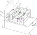
Fig. 1 is a schematic overall structure diagram of an embodiment of the present application.
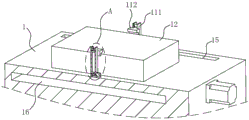
Fig. 2 is a schematic structural diagram for showing a connection relationship among the bracket, the slide plate, the suction cup, the first power assembly, the second power assembly and the jam prevention assembly in the embodiment of the present application.
FIG. 3 is a schematic cross-sectional view of a connection relationship among a carriage, a slide plate, a suction cup, a first power assembly, a support leg, a screw, and a fourth servo motor according to an embodiment of the present application.
Fig. 4 is a schematic structural diagram for showing the connection relationship among the sliding plate, the supporting block, the air cylinder, the suction cup and the first power assembly in the embodiment of the present application.
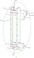
Fig. 5 is a schematic cross-sectional structure diagram for showing the connection relationship among the connection plate, the expansion plate, the screw rod and the screw block in the embodiment of the present application.
Fig. 6 is a schematic cross-sectional view for showing the connection relationship among the base, the paper board, the fixing plate and the paper pressing block in the embodiment of the present application.
Fig. 7 is an enlarged view for embodying a point a in fig. 6.
Description of reference numerals: 1. a base; 2. a paper feeding and guiding mechanism; 21. a rotating roller; 210. a paper feed gap; 3. a support; 31. a bearing frame; 310. a translation chute; 32. supporting legs; 321. a connecting rod; 4. a slide plate; 40. a guide chute; 41. a slider; 42. a fixed block; 5. a suction cup; 6. a first power assembly; 60. a lug; 61. a sleeve; 62. a first driving lever; 63. a second driving lever; 64. a first bevel gear; 65. a first servo motor; 66. a second bevel gear; 7. a second power assembly; 71. a bidirectional screw; 72. a second servo motor; 8. a holding assembly; 81. a support plate; 811. a connecting plate; 8110. adjusting the sliding chute; 812. a retractable plate; 8120. a cambered surface; 82. a screw rod; 83. twisting the block; 9. a sliding assembly; 91. a screw; 92. a fourth servo motor; 10. a support block; 11. a jam prevention assembly; 111. a fixing plate; 1110. a lifting chute; 112. paper pressing blocks; 1121. a rubber pad; 113. a conveyor belt; 114. a rotating wheel; 115. a third servo motor; 12. a paperboard; 13. a printing press; 14. a cylinder; 15. a sliding groove; 16. a containing cavity.
Detailed Description
The present application is described in further detail below with reference to figures 1-7.
The embodiment of the application discloses a paper feeding mechanism of a printing machine. Referring to fig. 1, printing machine paper feeding mechanism includes base 1, one side of base 1 is equipped with printing machine 13, base 1 is equipped with the guide mechanism 2 of form advancing on being close to the roof of printing machine 13 one side, the guide mechanism 2 of form advancing in this application is unanimous with the guide mechanism 2 of form advancing in the comparison file, the guide mechanism 2 of form advancing includes two live-rollers 21, it has paper feed space 210 to reserve between two live-rollers 21, base 1 is located the roof that the guide mechanism 2 of form advancing kept away from printing machine 13 one side and erects support 3, support 3 includes bearing frame 31 and the supporting leg 32 of fixed connection in bearing frame 31 diapire four corners, the one end fixed connection that bearing frame 31 was kept away from to supporting leg 32 is on the roof of base 1.
Referring to fig. 1 and 2, the bottom wall of the bearing frame 31 is connected with two sliding plates 4 along the Y-axis direction in a sliding manner, the bottom wall of each sliding plate 4 is connected with two suction cups 5 along the X-axis direction in a sliding manner, a first power component 6 for driving the two suction cups 5 to synchronously slide in the opposite directions or back to back is arranged on each sliding plate 4, a lifting component for driving the suction cups 5 to vertically reciprocate is arranged on the bottom wall of each sliding plate 4, a second power component 7 for driving the two sliding plates 4 to synchronously slide in the opposite directions or back to back is arranged on the top wall of the bearing frame 31, bearing components 8 for bearing the edges of the paper boards 12 are arranged on the side walls of the bearing frame 31 located on the two sides of the paper boards 12 in the transmission direction, and a sliding component 9 for driving the support 3 to slide in the paper boards 12 in the transmission direction is arranged on the base 1.
Referring to fig. 1 and 2, after a worker places a same batch of paper boards 12 with the same size on the top wall of the base 1 below the bracket 3, the two sliding plates 4 are driven to synchronously move towards or away from each other by the second power component 7 and the two suckers 5 are driven to synchronously move towards or away from each other by the first power component 6 according to the size of the batch of paper boards 12, so that the distance between the suckers 5 is adjusted, the suction force of the suckers 5 is uniformly dispersed, and the supporting component 8 is used for supporting the bottom walls of the edges of the two sides of the paper boards 12 in the transmission direction, so that the collapse degree of the edges of the paper boards 12 under the action of gravity is reduced, and the stability of the paper boards 12 in the transmission process of feeding the paper gaps 210 is further improved.
Referring to fig. 2 and 3, a translation sliding groove 310 is formed in the bottom wall of the bearing frame 31 along the Y-axis direction, sliding blocks 41 are fixedly connected to top walls of two ends of the sliding plate 4, the sliding blocks 41 slide in the translation sliding grooves 310, the longitudinal section of each sliding block 41 is in a T-shape, a fixing block 42 is fixedly connected to the top wall of the sliding plate 4, the fixing block 42 can be integrally formed with the sliding plate 4, the power assembly ii 7 includes a second servo motor 72 and a two-way screw rod 71, the second servo motor 72 is fixedly connected to the side wall of one side of the bearing frame 31, one end of the two-way screw rod 71 penetrates through the side wall of one fixing block 42 and is in threaded connection with the fixing block 42, and the other end of the two-way screw rod 71 penetrates through the side wall of the other fixing block 42 and is in threaded connection with the fixing block 42.
Referring to fig. 2 and 3, when the distance between the two sliding plates 4 is adjusted, the second servo motor 72 drives the two-way screw 71 to rotate, so that the two sliding plates 4 are driven by the two-way screw 71 to synchronously slide towards or away from each other under the guiding action of the translation chute 310, thereby adjusting the distance between the two suction cups 5 in the Y-axis direction.
Referring to fig. 3 and 4, a guide chute 40 is arranged on the bottom wall of the sliding plate 4 along the X-axis direction, a support block 10 is connected in the guide chute 40 in a sliding manner, the longitudinal section of the support block 10 is in a T-shape, the lifting element comprises an air cylinder 14, the air cylinder 14 is mounted on the bottom wall of the support block 10, a piston rod of the air cylinder 14 is connected with the suction cup 5, the power assembly one 6 comprises a sleeve 61 and a first driving rod 62, the sleeve 61 is rotatably connected to the bottom wall of the sliding plate 4 through the two lugs 60, threads are annularly arranged on the inner wall of the sleeve 61, the thread turning directions of the two ends of the sleeve 61 are opposite, one end of the first driving rod 62 is in threaded connection with one end of the sleeve 61, the other end of the first driving rod 62 penetrates through the side wall of one supporting block 10 and is in threaded connection with the supporting block 10, one end of the second driving rod 63 is in threaded connection with one end of the sleeve 61, and the other end of the second driving rod 63 penetrates through the side wall of the other supporting block 10 and is in threaded connection with the supporting block 10.
Referring to fig. 4, the power source includes a first bevel gear 64, a first servo motor 65 and a second bevel gear 66, the first bevel gear 64 is coaxially and fixedly connected to the peripheral side wall of the sleeve 61, the first servo motor 65 is fixedly connected to the bottom wall of the slide 4, the output shaft of the first servo motor 65 is connected to the second bevel gear 66, and the second bevel gear 66 is engaged with the first bevel gear 64.
Referring to fig. 3 and 4, when the positions of two suction cups 5 on the same sliding plate 4 are adjusted, the first servo motor 65 is used to sequentially drive the second bevel gear 66 and the first bevel gear 64 to rotate, so that the first bevel gear 64 drives the sleeve 61 to rotate, and under the action of the guide chute 40, the sleeve 61 drives the first driving rod 62 and the second driving rod 63 to synchronously move in the opposite direction or in the opposite direction, thereby adjusting the distance between the two suction cups 5.
Referring to fig. 2 and 5, the supporting assembly 8 includes a plurality of supporting plates 81 and a driving member for adjusting the length of the supporting plates 81, each supporting plate 81 includes a connecting plate 811 and an expansion plate 812, the longitudinal section of the connecting plate 811 is L-shaped, one end of the connecting plate 811 is fixedly connected to the outer side wall of the bearing frame 31, an adjusting chute 8110 is arranged on the end wall of the other end of the connecting plate 811, the expansion plate 812 is slidably connected to the adjusting chute 8110, the longitudinal section of the expansion plate 812 is rectangular, an arc surface 8120 is arranged on the end wall of one end of the expansion plate 812 far away from the connecting plate 811, the driving member includes a screw rod 82, the screw rod 82 is rotatably connected to the adjusting chute 8110, one end of the screw rod 82 is in threaded connection with the expansion plate 812, the other end of the screw rod 82 penetrates through the side wall of the connecting plate 811 and is rotatably connected with the connecting plate 811, one end of the screw rod 82 penetrating through the side wall of the connecting plate 811 is coaxially and fixedly connected with a screwing block 83, and the screwing block 83 can be integrally formed with the screw rod 82.
Referring to fig. 2 and 5, because sizes of different batches of paper boards 12 are not consistent, before a worker conveys paper boards 12 of different sizes, the length of the supporting plate 81 needs to be adjusted first, during adjustment, the worker screws the screwing block 83, so that the screwing block 83 drives the screw rod 82 to rotate, under the guiding action of the adjusting chute 8110, the screw rod 82 drives the expansion plate 812 to slide in the adjusting chute 8110, so that the supporting plate 81 can stably receive bottom walls of edges of the two sides of the paper boards 12 along the conveying direction, when the suction cups 5 adsorb the paper boards 12, the edges of the two sides of the paper boards 12 are stably received on the top wall of the supporting plate 81, so that the collapse degree of the edges of the paper boards 12 is reduced, and the stability of the paper boards 12 during conveying is improved.
Referring to fig. 2 and 6, the jam prevention assemblies 11 are disposed on the top walls of the base 1 on both sides of the conveying direction of the paper boards 12, and the jam prevention assemblies 11 are disposed below the brackets 3.
Referring to fig. 6 and 7, the anti-jam assembly 11 includes two fixing plates 111, a paper pressing block 112 and a power member, wherein the two fixing plates 111 are provided with a lifting sliding groove 1110 along the vertical direction on the opposite side walls, the shape of the longitudinal section of the paper pressing block 112 is similar to an L shape, the side wall of the paper pressing block 112 is provided with a guiding convex rib, the guiding convex rib can be integrally formed with the paper pressing block 112, the guiding convex rib is connected with the lifting sliding groove 1110 in a sliding manner, a rubber pad 1121 is bonded on the bottom wall of the paper pressing block 112 through glue, and the rubber pad 1121 is used for increasing the static friction between the paper pressing block 112 and the paper board 12, so as to improve the pressing effect of the paper pressing block 112 on the paper board.
Referring to fig. 7, the power member includes two rotating wheels 114, a conveyor belt 113 wound around the two rotating wheels 114, and a third servo motor 115, wherein one rotating wheel 114 is rotatably connected to the side wall at the top end of the two fixing plates 111, the other rotating wheel 114 is rotatably connected to the side wall at the bottom end of the two fixing plates 111, the third servo motor 115 is fixedly connected to the side wall at the bottom end of one of the fixing plates 111, and an output shaft of the third servo motor 115 is coaxially and fixedly connected to one of the rotating wheels 114.
Referring to fig. 6 and 7, in an initial state, the paper pressing block 112 abuts against the paper board 12 on the uppermost layer of the base 1, when the suction cup 5 adsorbs the first paper board 12, the abutting part of the first paper board 12 and the paper pressing block 112 bends and moves upwards, at this time, the third servo motor 115 is used for driving the rotating wheel 114 to rotate, so that the rotating wheel 114 drives the conveyor belt 113 to rotate, the conveyor belt 113 drives the paper pressing block 112 to vertically move downwards to press the rest of the paper boards 12, the first paper board 12 is separated from the second paper board 12, and the possibility of paper jamming is reduced.
Referring to fig. 3 and 6, base 1 is equipped with sliding tray 15 on the roof along 12 transmission direction both sides of cardboard, the bottom of supporting leg 32 is slided and is connected in sliding tray 15, fixedly connected with connecting rod 321 between two relative supporting legs 32, the length direction of connecting rod 321 is perpendicular with the transmission direction of cardboard 12, be equipped with in the top of base 1 and hold chamber 16, slip subassembly 9 includes fourth servo motor 92 and screw rod 91, screw rod 91 rotates to be connected in holding chamber 16, the one end of screw rod 91 runs through the lateral wall of two connecting rods 321 in order and with connecting rod 321 threaded connection, the other end of screw rod 91 runs through the lateral wall of base 1 and with the coaxial fixed connection of fourth servo motor 92's output shaft, fourth servo motor 92 fixed connection is on the lateral wall of base 1.
Referring to fig. 3 and 6, after the suction cup 5 sucks the paper sheet 12, the screw 91 is driven by the fourth servo motor 92 to rotate, so that the screw 91 drives the bracket 3 to slide along the conveying direction of the paper sheet 12 under the guiding action of the sliding slot 15, and after the side edge of one side of the paper sheet 12 enters the paper feeding gap 210 (fig. 1) between the two rotating rollers 21, the two rotating rollers 21 roll the paper sheet 12 into the printing machine 13 (fig. 1).
The implementation principle of the paper feeding mechanism of the printer in the embodiment of the application is as follows: when the paper feeding mechanism feeds paper, the position of the suction cup 5 is adjusted according to the size of the batch of paper boards 12, when the adjustment is performed, the second servo motor 72 is firstly utilized to drive the two-way screw 71 to rotate, the two sliding plates 4 are driven by the two-way screw 71 to synchronously slide towards or away from each other under the guiding action of the translation chute 310, the second bevel gear 66 and the first bevel gear 64 are sequentially driven by the first servo motor 65 to rotate, the first bevel gear 64 drives the sleeve 61 to rotate, the sleeve 61 drives the first driving rod 62 and the second driving rod 63 to synchronously slide towards or away from each other under the guiding action of the guide chute 40, so that the position adjustment of the four suction cups 5 is realized, the suction force of the suction cups 5 is uniformly dispersed, when the suction cups 5 are driven by the air cylinder 14 to vertically move downwards to adsorb the paper boards 12, the edges of the paper boards 12 are stably supported on the supporting plate 81 after being bent, and under the action of the anti-jamming paper assembly 11, the fourth servo motor 92 is used for driving the screw 91 to rotate, and under the guiding action of the sliding groove 15, the screw 91 drives the bracket 3 to slide along the conveying direction of the paper board 12, so that the edge of one side of the paper board 12 is aligned with the paper feeding gap 210, and the two rotating rollers 21 rotate to roll the paper board 12 into the printing machine 13; this application is through the cooperation of slide 4, sucking disc 5, power component 6 and two 7 of power component, adjusts the distance between the sucking disc 5 to according to the suction of the size homodisperse sucking disc 5 of cardboard 12, and utilize bearing subassembly 8 to accept the border of cardboard 12, be favorable to reducing the slump degree at cardboard 12 border, thereby stability when promoting cardboard 12 material loading.
The embodiments of the present invention are preferred embodiments of the present application, and the scope of protection of the present application is not limited by the embodiments, so: all equivalent changes made according to the structure, shape and principle of the present application shall be covered by the protection scope of the present application.
Claims (9)
1. The utility model provides a printing machine paper feeding mechanism, includes base (1) and sets up the guide mechanism (2) of form advancing on base (1), its characterized in that: a bracket (3) is arranged on the base (1), two sliding plates (4) are connected on the bracket (3) in a sliding way along the Y-axis direction, the sliding plate (4) is connected with two suckers (5) in a sliding manner along the X-axis direction, the sliding plate (4) is provided with a first power assembly (6) for driving the two suckers (5) to synchronously slide towards or away from each other, the sliding plate (4) is provided with a lifting piece for driving the sucker (5) to vertically reciprocate, a second power component (7) for driving the two sliding plates (4) to synchronously slide towards or away from each other is arranged on the support (3), the side walls of the bracket (3) positioned at two sides of the transmission direction of the paper board (12) are provided with supporting components (8) used for bearing the edges of the paper board (12), the base (1) is provided with a sliding component (9) for driving the support (3) to slide along the transmission direction of the paper board (12).
2. A printer paper feeding mechanism according to claim 1, characterized in that: the improved automatic lifting device is characterized in that a guide sliding groove (40) is formed in the bottom wall of the sliding plate (4) along the X-axis direction, a supporting block (10) is connected to the inner side of the guide sliding groove (40) in a sliding mode, the lifting piece comprises an air cylinder (14), the suckers (5) are arranged on a piston rod of the air cylinder (14), the first power assembly (6) comprises a sleeve (61) which is rotatably connected to the sliding plate (4), threads are arranged on the inner wall of the sleeve (61), the rotating directions of the threads on the inner walls of two ends of the sleeve (61) are opposite, one end of the sleeve (61) is in threaded connection with a first driving rod (62), one end, far away from the sleeve (61), of the first driving rod (62) is in threaded connection with one supporting block (10), the other end of the sleeve (61) is in threaded connection with a second driving rod (63), one end, far away from the sleeve (61), of the second driving rod (63), is in threaded connection with the other supporting block (10), and a power source for driving the sleeve (61) to rotate is arranged on the support (3).
3. A printer paper feeding mechanism according to claim 2, characterized in that: the power source comprises a first bevel gear (64) coaxially arranged on the peripheral side wall of the sleeve (61), a first servo motor (65) is arranged on the sliding plate (4), an output shaft of the first servo motor (65) is connected with a second bevel gear (66), and the second bevel gear (66) is meshed with the first bevel gear (64).
4. A printer paper feeding mechanism according to claim 1, characterized in that: the power assembly II (7) comprises a bidirectional screw rod (71), the bidirectional screw rod (71) is rotatably connected to the support (3), one end of the bidirectional screw rod (71) is in threaded connection with one of the sliding plates (4), the other end of the bidirectional screw rod (71) is in threaded connection with the other sliding plate (4), a second servo motor (72) is arranged on the support (3), and the second servo motor (72) is coaxially connected with the bidirectional screw rod (71).
5. A printer paper feeding mechanism according to claim 1, characterized in that: bearing subassembly (8) include a plurality of bearing board (81), bearing board (81) are including connecting plate (811) and expansion plate (812), the one end setting of connecting plate (811) is on support (3), be equipped with on the end wall of the connecting plate (811) other end and adjust spout (8110), expansion plate (812) slide and connect in adjusting spout (8110), be equipped with the driving piece that is used for driving expansion plate (812) and slides on connecting plate (811).
6. The printer paper feeding mechanism of claim 5, wherein: the driving piece comprises a screw rod (82), the screw rod (82) is rotatably connected in an adjusting sliding groove (8110), one end of the screw rod (82) is in threaded connection with a telescopic plate (812), the other end of the screw rod (82) penetrates through the side wall of a connecting plate (811) and is in threaded connection with the connecting plate (811), and one end, penetrating through the connecting plate (811), of the screw rod (82) is connected with a screwing block (83).
7. The printer paper feeding mechanism of claim 5, wherein: an arc surface (8120) is arranged on the end wall of one end, far away from the connecting plate (811), of the expansion plate (812).
8. A printer paper feeding mechanism according to claim 1, characterized in that: the base (1) is provided with a paper jam prevention assembly (11).
9. A printer paper feeding mechanism according to claim 8, wherein: prevent card paper subassembly (11) and include two fixed plates (111), two it is connected with paper pressing block (112) to slide along vertical direction on the relative lateral wall of fixed plate (111), be equipped with on fixed plate (111) and be used for driving the power piece that the vertical reciprocal of paper pressing block (112) slided.
Priority Applications (1)
| Application Number | Priority Date | Filing Date | Title |
|---|---|---|---|
| CN202120614158.3U CN214399086U (en) | 2021-03-25 | 2021-03-25 | Paper feeding mechanism of printer |
Applications Claiming Priority (1)
| Application Number | Priority Date | Filing Date | Title |
|---|---|---|---|
| CN202120614158.3U CN214399086U (en) | 2021-03-25 | 2021-03-25 | Paper feeding mechanism of printer |
Publications (1)
| Publication Number | Publication Date |
|---|---|
| CN214399086U true CN214399086U (en) | 2021-10-15 |
Family
ID=78030538
Family Applications (1)
| Application Number | Title | Priority Date | Filing Date |
|---|---|---|---|
| CN202120614158.3U Active CN214399086U (en) | 2021-03-25 | 2021-03-25 | Paper feeding mechanism of printer |
Country Status (1)
| Country | Link |
|---|---|
| CN (1) | CN214399086U (en) |
Cited By (1)
| Publication number | Priority date | Publication date | Assignee | Title |
|---|---|---|---|---|
| CN114889923A (en) * | 2022-05-24 | 2022-08-12 | 罗博特科智能科技股份有限公司 | Scraps of paper separation conveyor and silicon chip packaging production line |
-
2021
- 2021-03-25 CN CN202120614158.3U patent/CN214399086U/en active Active
Cited By (1)
| Publication number | Priority date | Publication date | Assignee | Title |
|---|---|---|---|---|
| CN114889923A (en) * | 2022-05-24 | 2022-08-12 | 罗博特科智能科技股份有限公司 | Scraps of paper separation conveyor and silicon chip packaging production line |
Similar Documents
| Publication | Publication Date | Title |
|---|---|---|
| CN110526020B (en) | Carton packing is with automatic dislocation of overturning piles up device | |
| CN214399086U (en) | Paper feeding mechanism of printer | |
| CN208775956U (en) | A kind of conveyer of four-color press | |
| CN214934318U (en) | Stable green printing device of feeding | |
| CN210594402U (en) | Small offset press | |
| CN110342288B (en) | Paper feeding mechanism of printing machine | |
| CN112551210A (en) | Automatic paper feeding device for printing machine | |
| CN212194404U (en) | Automatic box pasting machine | |
| CN213201639U (en) | Conveying mechanism and cutting machine | |
| CN112520472B (en) | Paper collecting device for web printing machine | |
| CN211195336U (en) | Efficient color printing machine | |
| CN209904308U (en) | Page turning device for coil book manufacturing | |
| CN219823049U (en) | Printing machine feed mechanism | |
| CN112125004A (en) | Conveying mechanism and cutting machine | |
| CN217050810U (en) | Printing machine convenient to paper aligns | |
| KR20130136273A (en) | Automatic sheet feeder for thomson cutter | |
| CN214732962U (en) | Tray adjusting mechanism of printing machine | |
| CN214298409U (en) | Paper conveying device of printing machine | |
| CN219031139U (en) | Cardboard positioning mechanism for ink printer | |
| CN219098172U (en) | Deviation correcting mechanism for printing machine | |
| CN217862997U (en) | Feeding device of leather shell machine | |
| CN216686670U (en) | Printing paper conveying device with sucking and feeding functions | |
| CN218428717U (en) | Non-stop folding blanking device for die cutting machine | |
| CN212889212U (en) | Novel edge covering mechanism | |
| CN116424880B (en) | Multistation books stacking equipment with paper filling function |
Legal Events
| Date | Code | Title | Description |
|---|---|---|---|
| GR01 | Patent grant | ||
| GR01 | Patent grant |