CN214394786U - Automatic concrete mixing device - Google Patents
Automatic concrete mixing device Download PDFInfo
- Publication number
- CN214394786U CN214394786U CN202023211710.9U CN202023211710U CN214394786U CN 214394786 U CN214394786 U CN 214394786U CN 202023211710 U CN202023211710 U CN 202023211710U CN 214394786 U CN214394786 U CN 214394786U
- Authority
- CN
- China
- Prior art keywords
- stirring
- box
- stirring box
- rotating pipe
- stirring barrel
- Prior art date
- Legal status (The legal status is an assumption and is not a legal conclusion. Google has not performed a legal analysis and makes no representation as to the accuracy of the status listed.)
- Active
Links
Images

Abstract
The utility model discloses an automatic concrete stirring device, which relates to the technical field of constructional engineering and comprises a base, wherein a pressure sensor for detecting the pressure is fixedly arranged in the base; a stirring box is fixedly arranged at the upper end of the base, and a stirring barrel is arranged in the stirring box; the left end of the stirring barrel is uniformly and fixedly provided with a lower fixing rod, and the left end of the lower fixing rod is fixedly connected with a lower end plate; the right end of the stirring barrel is uniformly and fixedly provided with an upper fixed rod, and the right end of the upper fixed rod is fixedly connected with an upper end plate; a spiral groove is formed in the inner wall of the stirring barrel; a rotating pipe is fixedly arranged between the upper end plate and the lower end plate; has the advantages that: the concrete is stirred in a rolling mode through the stirring barrel and the spiral groove on the inner wall of the stirring barrel, so that the stirring is more sufficient and uniform; the rotating pipes are arranged to uniformly spray water to the concrete, so that the concrete is stirred fully; a pressure sensor is arranged to detect the downward pressure of the stirring box, so that the automatic stirring starting operation is realized.
Description
Technical Field
The utility model relates to a building engineering technical field especially relates to an automatic concrete mixing device.
Background
A concrete mixer is a machine for mixing cement, gravel aggregate and water according to a certain proportion and mixing the mixture into a concrete mixture, and is widely applied to civil and architectural engineering, in the architectural engineering, the concrete mixer is required to be frequently used for mixing concrete, wherein a horizontal concrete mixer is one of the concrete mixers, the horizontal concrete mixer comprises a base and a mixing tank which is rotatably connected with the base, a mixing paddle penetrates through the mixing tank, a machine box is arranged on the base, a motor for driving the mixing paddle to rotate is arranged on the machine box, a feeding port is arranged at the top of the mixing tank, a cover plate is arranged on the feeding port, the cement, the gravel aggregate and the water are added into the mixing tank through the feeding port, then the mixing paddle is driven by the motor for mixing, the cover plate is opened after the mixing is finished, then the mixing tank is rotated to pour out the concrete inside, but the cover plate is required to be taken down and placed in place before the concrete is poured out each time, resulting in complicated operation.
Horizontal concrete mixer when unloading, pour the rotatory concrete with the agitator in through the pulling hand lever, at the in-process of unloading, need alone the pulling hand lever to make the discharging pipe keep down to one side, need alone in addition to clear out the interior concrete of agitator, pour the concrete in the agitator, be not convenient for operate alone.
SUMMERY OF THE UTILITY MODEL
The utility model aims at providing an automatic concrete mixing device for solving the above-mentioned problem.
The utility model discloses a following technical scheme realizes above-mentioned purpose:
an automatic concrete stirring device comprises a base, wherein a pressure sensor for detecting the pressure is fixedly arranged in the base; a stirring box is fixedly arranged at the upper end of the base, and a stirring barrel is arranged in the stirring box; the left end of the stirring barrel is uniformly and fixedly provided with a lower fixing rod, and the left end of the lower fixing rod is fixedly connected with a lower end plate; the right end of the stirring barrel is uniformly and fixedly provided with an upper fixed rod, and the right end of the upper fixed rod is fixedly connected with an upper end plate; a spiral groove is formed in the inner wall of the stirring barrel; a rotating pipe is fixedly arranged between the upper end plate and the lower end plate, the rotating pipe is hollow, a water spraying hole is formed in the rotating pipe, and two ends of the rotating pipe are respectively connected with the stirring box through bearings; the right end of the rotating pipe extends out of the stirring box and is connected with a water inlet pipe through a bearing; a driving box is fixedly installed at the left end of the stirring box, a driving motor is installed in the driving box, and an output shaft of the driving motor extends into the stirring box and is fixedly connected with the left end of the rotating pipe; agitator tank left side below corresponds dead lever position seal installs the discharging pipe down, agitator tank right side top corresponds go up dead lever position seal and install the feeder hopper.
Preferably: the agitator tank is the slope setting of low right height on a left side.
Preferably: a control panel is fixedly installed on the base, and a controller is arranged in the control panel.
Compared with the prior art, the beneficial effects of the utility model reside in that: the concrete is stirred in a rolling mode through the stirring barrel and the spiral groove on the inner wall of the stirring barrel, so that the stirring is more sufficient and uniform; the rotating pipes are arranged to uniformly spray water to the concrete, so that the concrete is stirred fully; a pressure sensor is arranged to detect the downward pressure of the stirring box, so that the stirring work is automatically started; the spiral groove is an arc groove, so that the bonding of concrete is reduced, and the stirring effect is influenced.
Drawings
In order to more clearly illustrate the embodiments of the present invention or the technical solutions in the prior art, the drawings needed to be used in the description of the embodiments or the prior art will be briefly described below, it is obvious that the drawings in the following description are only some embodiments of the present invention, and for those skilled in the art, other drawings can be obtained according to these drawings without inventive exercise.
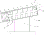
Fig. 1 is a schematic view of the structure of the automatic concrete mixer of the present invention.
Fig. 2 is a front view of the automatic concrete mixer of the present invention.
The reference numerals are explained below:
1. a base; 2. a discharge pipe; 3. a drive box; 4. a drive motor; 5. a lower end plate; 6. a lower fixing rod; 7. a stirring barrel; 8. pipe rotation; 9. a water spray hole; 10. a feed hopper; 11. an upper fixing rod; 12. an upper end plate; 13. a water inlet pipe; 14. a helical groove; 15. a pressure sensor; 16. and (4) a stirring box.
Detailed Description
In the description of the present invention, it is to be understood that the terms "central", "longitudinal", "lateral", "upper", "lower", "front", "rear", "left", "right", "vertical", "horizontal", "top", "bottom", "inner", "outer", etc., indicate orientations or positional relationships based on those shown in the drawings, and are used only for convenience in describing and simplifying the description, but not for indicating or implying that the device or element being referred to must have a particular orientation, be constructed and operated in a particular orientation, and thus are not to be construed as limiting the invention, and further that the terms "first", "second", etc., are used only for descriptive purposes and are not to indicate or imply relative importance or imply the number of technical features being referred to, whereby the features defined as "first", "second", etc., may explicitly or implicitly include one or more such features, in the description of the present invention, "a plurality" means two or more unless otherwise specified.
In the description of the present invention, it is to be noted that, unless otherwise explicitly specified or limited, the terms "mounted," "connected," and "connected" are to be construed broadly, and may be, for example, fixedly connected, detachably connected, or integrally connected; can be mechanically or electrically connected; the two elements may be directly connected or indirectly connected through an intermediate medium, or the two elements may be connected through an intermediate medium, and the specific meaning of the above terms in the present invention can be understood by those skilled in the art through specific situations.
The present invention will be further explained with reference to the accompanying drawings:
as shown in fig. 1-2, an automatic concrete mixer includes a base 1, a pressure sensor 15 for detecting pressure is fixedly installed in the base 1; the upper end of the base 1 is fixedly provided with a stirring box 16, the stirring box 16 is used for supporting and stirring, a stirring barrel 7 is arranged in the stirring box 16, and the stirring barrel 7 is used for rotating and stirring; the left end of the stirring barrel 7 is uniformly and fixedly provided with a lower fixing rod 6, and the left end of the lower fixing rod 6 is fixedly connected with a lower end plate 5; the right end of the stirring barrel 7 is uniformly and fixedly provided with an upper fixed rod 11, and the right end of the upper fixed rod 11 is fixedly connected with an upper end plate 12; a spiral groove 14 is arranged on the inner wall of the stirring barrel 7; a rotating pipe 8 is fixedly arranged between the upper end plate 12 and the lower end plate 5, the rotating pipe 8 is used for supporting and spraying water, the rotating pipe 8 is hollow, a water spraying hole 9 is formed in the rotating pipe 8, and two ends of the rotating pipe 8 are respectively connected with a stirring box 16 through bearings; a stirring box 16 extends out of the right end of the rotating pipe 8 and is connected with a water inlet pipe 13 through a bearing, and the water inlet pipe 13 is used for water inlet; a driving box 3 is fixedly installed at the left end of the stirring box 16, the driving box 3 is used for supporting and fixing, a driving motor 4 is installed inside the driving box 3, the driving motor 4 is used for driving, and an output shaft of the driving motor 4 extends into the stirring box 16 and is fixedly connected with the left end of the rotating pipe 8; a discharging pipe 2 is hermetically arranged at the lower part of the left side of the stirring box 16 corresponding to the position of the lower fixing rod 6, the discharging pipe 2 is used for discharging, a feeding hopper 10 is hermetically arranged at the upper part of the right side of the stirring box 16 corresponding to the position of the upper fixing rod 11, and the feeding hopper 10 is used for feeding; the stirring box 16 is obliquely arranged with the left lower part and the right higher part; a control panel is fixedly arranged on the base 1 and used for manual operation, and a controller is arranged in the control panel and used for controlling; the spiral groove 14 is a cambered surface groove, so that concrete adhesion is reduced, and the stirring effect is influenced.
The working principle is as follows: during the use, external power source circular telegram, concrete raw materials that will need the stirring are poured into agitator tank 16 from feeder hopper 10 in, pressure sensor 15 detects pressure variation, controller control, start driving motor 4 and drive agitator 7 and the rotation of rotary drum 8, inlet tube 13 supplies water, water is from hole for water spraying 9 blowout and is added water operation when concrete raw materials overturns in agitator tank 7, because the shape of helicla flute 14 on the agitator tank 7 inner wall, make the concrete when the stirring, move left while stirring, the concrete of stirring completion is discharged from the discharge gate.
The drive motor 4, pressure sensor 15, control panel and controller are all common standard components or components known to those skilled in the art, the structure and principle of which are known to those skilled in the art through technical manuals or through routine experimentation, and therefore will not be described herein too much.
Having shown and described the basic principles, essential features and advantages of the invention, it should be understood by those skilled in the art that the present invention is not limited by the foregoing embodiments, which are merely illustrative, but rather are intended to cover various changes and modifications within the spirit and scope of the invention as defined by the appended claims.
Claims (3)
1. The utility model provides an automatic concrete mixing device, includes base (1), its characterized in that: a pressure sensor (15) for detecting the pressure is fixedly arranged in the base (1); a stirring box (16) is fixedly arranged at the upper end of the base (1), and a stirring barrel (7) is arranged in the stirring box (16); a lower fixing rod (6) is uniformly and fixedly arranged at the left end of the stirring barrel (7), and a lower end plate (5) is fixedly connected at the left end of the lower fixing rod (6); an upper fixed rod (11) is uniformly and fixedly arranged at the right end of the stirring barrel (7), and an upper end plate (12) is fixedly connected at the right end of the upper fixed rod (11); a spiral groove (14) is formed in the inner wall of the stirring barrel (7); a rotating pipe (8) is fixedly arranged between the upper end plate (12) and the lower end plate (5), the rotating pipe (8) is hollow, a water spraying hole (9) is formed in the rotating pipe (8), and two ends of the rotating pipe (8) are respectively connected with the stirring box (16) through bearings; the right end of the rotating pipe (8) extends out of the stirring box (16) and is connected with a water inlet pipe (13) through a bearing; a driving box (3) is fixedly installed at the left end of the stirring box (16), a driving motor (4) is installed inside the driving box (3), and an output shaft of the driving motor (4) extends into the stirring box (16) and is fixedly connected with the left end of the rotating pipe (8); agitator tank (16) left side below corresponds lower dead lever (6) position seal installs discharging pipe (2), agitator tank (16) right side top corresponds last dead lever (11) position seal installs feeder hopper (10).
2. An automatic concrete mixing apparatus according to claim 1, wherein: the stirring box (16) is obliquely arranged with a lower left part and a higher right part.
3. An automatic concrete mixing apparatus according to claim 1, wherein: a control panel is fixedly installed on the base (1), and a controller is arranged in the control panel.
Priority Applications (1)
| Application Number | Priority Date | Filing Date | Title |
|---|---|---|---|
| CN202023211710.9U CN214394786U (en) | 2020-12-28 | 2020-12-28 | Automatic concrete mixing device |
Applications Claiming Priority (1)
| Application Number | Priority Date | Filing Date | Title |
|---|---|---|---|
| CN202023211710.9U CN214394786U (en) | 2020-12-28 | 2020-12-28 | Automatic concrete mixing device |
Publications (1)
| Publication Number | Publication Date |
|---|---|
| CN214394786U true CN214394786U (en) | 2021-10-15 |
Family
ID=78041487
Family Applications (1)
| Application Number | Title | Priority Date | Filing Date |
|---|---|---|---|
| CN202023211710.9U Active CN214394786U (en) | 2020-12-28 | 2020-12-28 | Automatic concrete mixing device |
Country Status (1)
| Country | Link |
|---|---|
| CN (1) | CN214394786U (en) |
-
2020
- 2020-12-28 CN CN202023211710.9U patent/CN214394786U/en active Active
Similar Documents
| Publication | Publication Date | Title |
|---|---|---|
| CN214394786U (en) | Automatic concrete mixing device | |
| CN211682887U (en) | Mixing device for building automation | |
| CN219466533U (en) | Concrete mixing device for house construction engineering | |
| CN112248229A (en) | Concrete mixer | |
| CN215442981U (en) | Fluorgypsum self-leveling construction equipment | |
| CN217292826U (en) | Mortar mixer convenient to stirring | |
| CN211537335U (en) | Storage device for mixed preparation of chemical raw materials | |
| CN211362890U (en) | Concrete stirring and feeding device | |
| CN217434672U (en) | Horizontal shaft forced mixer discharge apparatus capable of discharging at multiple angles | |
| CN208824382U (en) | A kind of concrete admixture stirring Preparation equipment | |
| CN219153320U (en) | Automatic concrete feeding and stirring device | |
| CN214394787U (en) | Environmental protection concrete mixer is used in building engineering construction | |
| CN209775057U (en) | aerated concrete block pouring device | |
| CN219190720U (en) | Concrete mixing box | |
| CN220348727U (en) | Foam light soil working station | |
| CN211640451U (en) | Storage box for transporting dry-mixed mortar | |
| CN218307377U (en) | Light-duty whitewash compounding device for gypsum production | |
| CN220741685U (en) | Full-automatic mortar mixer | |
| CN210361907U (en) | High and large formwork construction equipment for constructional engineering | |
| CN219272723U (en) | Mixing device for magnesia carbon brick production | |
| CN209771974U (en) | Stirring device for carbide slag brick making | |
| CN219522565U (en) | Mixer convenient to pay-off | |
| CN215549736U (en) | Concrete additive feeding equipment | |
| CN218111217U (en) | Agitating unit is used in concrete production | |
| CN220280042U (en) | Material feeding unit is used in concrete production |
Legal Events
| Date | Code | Title | Description |
|---|---|---|---|
| GR01 | Patent grant | ||
| GR01 | Patent grant |