CN214387172U - Micro steaming and baking device - Google Patents
Micro steaming and baking device Download PDFInfo
- Publication number
- CN214387172U CN214387172U CN202022861301.7U CN202022861301U CN214387172U CN 214387172 U CN214387172 U CN 214387172U CN 202022861301 U CN202022861301 U CN 202022861301U CN 214387172 U CN214387172 U CN 214387172U
- Authority
- CN
- China
- Prior art keywords
- air
- heat dissipation
- air duct
- main
- micro
- Prior art date
- Legal status (The legal status is an assumption and is not a legal conclusion. Google has not performed a legal analysis and makes no representation as to the accuracy of the status listed.)
- Active
Links
Images


Abstract
The utility model relates to a little roast device that evaporates, it includes box, the door body, culinary art chamber, microwave generating device, steam generating device and main heater unit spare, and this main heater unit spare includes two main heating pipes, and these two main heating pipes are in culinary art chamber top with horizontal spaced's mode longitudinal arrangement. The utility model discloses in, because main heating pipe longitudinal arrangement to horizontal radiant heat has avoided the direct radiation to the door body, has avoided the phenomenon that door body surface temperature rises on the one hand like this, and on the other hand has reduced thermal waste, makes the culinary art effect better.
Description
Technical Field
The utility model relates to the technical field of household appliances, especially, relate to a evaporate roast device a little.
Background
In the existing micro-steaming and baking integrated machine product, the heating pipe for barbecuing is installed in a transverse mode, that is, the heating pipe 100 is installed in a mode of being horizontal to the plane of the door body 200, as shown in fig. 1 or fig. 2, but the installation mode can cause the surface temperature of the door body of the micro-steaming and baking integrated machine to be increased, because the radiant heat of the heating pipe 100 can radiate to the door body 200 as shown by an arrow vertical to the door body 200, and if the fan 300 is installed on the side as a side hot air fan as shown in fig. 2, the air suction direction of the fan 300 is just vertical to the radiant heat direction of the heating pipe 100, so that the center instability is formed in the cooking cavity 400, as shown by the vertical center of the arrow, the food at the center of the cooking cavity 400 can not be effectively heated.
Therefore, the surface temperature of the door body is increased due to the transverse installation of the heating pipe, and the transverse installation mode is not suitable for matching with lateral hot air, namely, the fan is not suitable for side installation.
SUMMERY OF THE UTILITY MODEL
Therefore, the utility model provides a can effectively avoid the temperature rise of a body and reduce the little roast device that evaporates of heat waste will be favorable.
In order to achieve the above object, the utility model provides a little roast device that evaporates, it includes box, the door body, cooks chamber, microwave generating device, steam generating device and main heater subassembly, and wherein, this main heater subassembly includes two main heating pipes, and these two main heating pipes are with horizontal spaced mode longitudinal arrangement in culinary art chamber top.
The utility model discloses in, main heating pipe longitudinal arrangement to horizontal radiant heat has avoided the direct radiation to the door body, has avoided the phenomenon that door body surface temperature rises like this on the one hand, and on the other hand has reduced thermal waste, makes the culinary art effect better.
Furthermore, above-mentioned box is including being located the preceding box outside the culinary art chamber, and this preceding box outside-in includes shell, inner shell and inner bag, is provided with a pair of vertical opening on the inner bag roof, and two main heating pipes are installed at inner shell roof downside and just right with this a pair of vertical opening.
Through this structural arrangement, make the main heating pipe can get into the cooking chamber with the heat radiation.
Still further, the hot air system comprises a side hot air structure, wherein the side hot air structure comprises a side hot air motor arranged on one side of the inner shell, a side hot air fan in driving connection with the side hot air motor, an air suction opening and an air supply opening, the air suction opening and the side hot air fan are arranged on one side of the inner container in a facing mode, and the air supply opening is arranged on the periphery of the air suction opening.
Through this side hot-blast structure setting of side for side hot-blast fan can be through the hot-blast extraction of suction opening in with the culinary art intracavity, and send the hot-blast culinary art chamber of sending back again of taking out through the supply-air outlet, thereby stir the hot-blast of culinary art intracavity, make the heating more even, and because the fan sucks the parallel nothing of wind direction and the radiation direction of main heating pipe and intersects, can not appear the air pressure point in the culinary art chamber, it is effectual to bake.
Still further, the side heat wind structure further includes a side heating duct provided corresponding to the air blowing port and arranged around the side heat wind fan.
Through the setting of side heating pipe, can make the hot-blast back of getting the heating of following the culinary art chamber of taking out, guarantee the heating effect better.
Still further, a side hot air fan is located at a central position on a side of the inner case, and the side heat duct is arranged in a square structure surrounding the side hot air fan.
Through this structure setting for the hot-blast center of can following of culinary art intracavity is taken out, sends into all around from, and stirring effect is better.
Still further, the box body also comprises a rear box body which is enclosed into an electric room, the rear box body comprises a rear plate, an outer rear plate, a shell and a bottom plate, and two main cooling fans, a microwave generating device and a steam generating device are arranged in the electric room.
Through the structure, the micro-steaming and baking device is more reasonable in layout, more time-saving and labor-saving in assembly and capable of having sufficient space to provide double cooling fans to provide sufficient air quantity for better cooling by partitioning the cooking cavity and the electric room.
Still further, still include heat dissipation air duct system, this heat dissipation air duct system includes the main air duct structure that is used for the electric room heat dissipation, is used for the side air duct structure of the heat dissipation of side hot-blast motor, and is used for the radiating top air duct structure of main heater subassembly, and wherein, side air duct structure and top air duct structure are linked together with main air duct structure respectively.
Through above-mentioned wind channel structure, can carry out abundant heat dissipation to electric room, to main heater subassembly and side wind channel structure.
Still further, the main air duct structure comprises a main heat dissipation air duct, a side air inlet and a rear air inlet, a side air outlet and a rear air outlet, wherein the main heat dissipation air duct is formed by a cavity of the electric chamber, the side air inlet and the rear air inlet are formed on one end of the rear box body and communicated with the main heat dissipation air duct, and the side air outlet and the rear air outlet are formed on the other end of the rear box body and communicated with the main heat dissipation air duct.
The two main radiating fans suck outside air into the electric chamber through the side air inlet and the rear air inlet on the rear box body and are mixed with air entering the electric chamber from the side air duct structure through the upper air inlet, after the electric components in the electric chamber are cooled, one part of the air is discharged from the electric chamber through the side air outlet and the rear air outlet, the other part of the air enters the top air duct structure through the upper air outlet and then returns to the electric chamber through the upper air inlet, and the two main radiating fans circulate in a reciprocating mode.
Still further, the side air duct structure includes a side air inlet formed on one side of the outer casing, a side heat dissipation air duct formed between one side of the outer casing and one side of the inner casing, and an upper air outlet communicating the side heat dissipation air duct and the main heat dissipation air duct, wherein the upper air outlet is formed on the upper left side of the rear plate and is located between the two main heat dissipation fans and the side air inlet.
Through this side inlet, the hot-blast motor of offside hot-blast wind channel offside is dispelled the heat to external wind entering side, and the wind after the heat dissipation is sucked to the electric indoor through last inlet opening.
Still further, the top air duct structure comprises an upper air inlet, an annular heat dissipation air duct formed between a top plate of the outer shell and a top plate of the inner shell, and an upper air outlet, wherein the upper air inlet is formed at the upper right side of the rear plate and is located between the two main heat dissipation fans and the side air outlet, and air from the main air duct structure enters the annular heat dissipation air duct through the upper air inlet under the action of the two main heat dissipation fans and then returns to the main air duct structure from the upper air outlet.
Through the structure, the main heater assembly can be effectively cooled.
These and other aspects of the invention will be apparent from and elucidated with reference to the embodiments described hereinafter.
Drawings
The structure of the present invention, together with further objects and advantages thereof, will be best understood from the following description taken in conjunction with the accompanying drawings, in which like reference characters identify like elements:
FIG. 1 is a schematic view of an arrangement of a barbecue heating pipe and a fan of a conventional micro-steaming and baking integrated machine, wherein the fan is arranged at the rear;
FIG. 2 is a schematic view of another arrangement of a grill heating pipe and a fan of a conventional micro-grill integrated machine, in which the fan is disposed laterally;
fig. 3 is a schematic view showing the arrangement of a main heating pipe and a side hot air fan of a micro-steaming and baking apparatus according to an embodiment of the present invention;
fig. 4 is a schematic perspective view of a micro-steaming device according to an embodiment of the present invention;
FIG. 5 is an exploded perspective view of the micro-steaming device shown in FIG. 4;
FIG. 6 is a sectional view of the micro steaming device shown in FIG. 4;
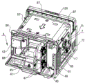
FIG. 7 is a perspective view of the micro-steaming device shown in FIG. 4, viewed from the rear left, after most of the outer shell and the outer back plate have been removed;
FIG. 8 is a perspective view of the micro-steaming device shown in FIG. 4, as viewed from the front right, after the outer case and the door body are removed;
FIG. 9 is a schematic perspective view of the micro steaming device shown in FIG. 4 after removing the outer case and opening the door;
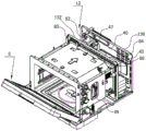
fig. 10 is a plan view of the micro-steaming device shown in fig. 4, after removing the outer case, but in which a frequency converter in an electric chamber is replaced with a transformer and a high-voltage capacitor, and in which the direction of the air flow is shown by an arrow line.
Detailed Description
The following description of the embodiments of the present invention will be made with reference to the accompanying drawings.
As shown in fig. 3, and referring to fig. 4 to 6, the micro-steaming and baking apparatus according to an embodiment of the present invention includes a cabinet 1, a cooking chamber 2, a door 3, a steam generating device 42, a main heater assembly including two main heating pipes 5, a microwave generating device including a magnetron 41 and a bottom waveguide 43, a side hot air structure 7, and a heat radiation duct system 8. As shown in fig. 6, in the present embodiment, two main heating pipes 5 of the main heater assembly are arranged longitudinally above the cooking chamber 2 in a laterally spaced manner.
As shown in fig. 4 and 5, and with reference to fig. 6 to 8, the cabinet 1 comprises a front cabinet 11 and a rear cabinet 13, which use the same casing 10, and the portion of the cabinet 1 that encloses the cooking chamber 2 with the door 3 is the front cabinet 11, and the portion of the cabinet 1 that encloses the electrical chamber 4 is the rear cabinet 13. As shown in fig. 6, the front box 11 includes an outer shell 10, an inner shell 12 and an inner container 14 from outside to inside, a pair of longitudinal openings or a pair of longitudinal opening groups (not shown) is disposed on a top plate 140 of the inner container 14, and two main heating pipes 5 are mounted on a lower side of the top plate 120 of the inner shell 12 and are opposite to the pair of longitudinal openings or the pair of longitudinal opening groups. The rear case 13 includes a rear plate 132, an outer rear plate 130, the housing 10, and a bottom plate (not shown).
As shown in fig. 7 to 9, a steam generator 42, a magnetron 41, an inverter 45, two main heat dissipation fans 47, and a computer board 49 are disposed in the electric room 4. Of course, in another embodiment, the frequency converter 45 may be replaced with a transformer 450 and a capacitor 451 according to the customer's needs, as shown in fig. 10. However, the configurations of the side hot air structure 7 and the heat dissipation air duct system 8 to be described below are not affected by the inverter or the transformer.
As shown in fig. 6 to 8, the side hot air structure 7 includes a side hot air motor 71 installed on one side of the inner case 12, a side hot air fan 73 drivingly connected by the side hot air motor 71, a side heating pipe 75 (see fig. 6), an air suction opening 141 and an air blowing opening 143 provided on one side of the inner container 14. The side hot air fan 73 is located at a central position on one side of the inner case 12, and the side heating duct 75 is arranged in a substantially square structure surrounding the side hot air fan 73 and is preferably disposed to face the air blowing port 143, so that the heated hot air after reheating can be returned into the cooking chamber 2 via the air blowing port 143. In the present embodiment, the term "one side" refers to the left side as viewed from the door 3 rearward.
As shown in fig. 8, the suction port 141 is provided opposite to the side hot air fan 73, and the blowing ports 143 are arranged around the suction port 141. It should be understood that, in the present embodiment, the suction port 141 is a suction port group composed of a plurality of small suction ports; the air blowing ports 143 are provided in a plurality of positions, which are arranged around the suction port 141, and each air blowing port 143 is also a group of air blowing ports consisting of a plurality of small air blowing ports.
It should be noted that, in the present embodiment, the heat dissipation air duct system 8 includes a main air duct structure for dissipating heat of the electrical room 4, a side air duct structure for dissipating heat of the side hot air motor 71, and a top air duct structure for dissipating heat of the main heater assembly, wherein the side air duct structure and the top air duct structure are respectively communicated with the main air duct structure. Specifically, as shown in fig. 7 and referring to fig. 4, 5 and 8, in the present embodiment, the main air duct structure includes a main heat dissipation air duct 40, a side air inlet 81, a rear air inlet 82, a side air outlet 83 and a rear air outlet 84, wherein the main heat dissipation air duct 40 is formed by a cavity of the electrical chamber 4; a side intake opening 81 (see fig. 4 and 7) and a rear intake opening 82 (see fig. 9) are formed at one end of the rear case 13, the former being the side intake opening 81 formed at the housing 10, and the latter being the rear intake opening 82 formed at the outer rear plate 130 of the rear case 13; a side outlet 83 (see fig. 5) and a rear outlet 84 (see fig. 9) are formed at the other end of the rear case 13, the former being the side outlet 83 formed at the casing 10, and the latter being the rear outlet 84 formed at the outer rear plate 130 of the rear case 13.
As shown in fig. 7 and 10, and referring to fig. 4, the side air duct structure includes a side air inlet 72 formed on one side (left side) of the outer casing 10, a side heat dissipation air duct 17 formed between one side (left side) of the outer casing 10 and one side (left side) of the inner casing 12, and an upper air outlet 85 communicating the side heat dissipation air duct 17 and the main heat dissipation air duct 40, wherein the upper air outlet 85 is formed on the upper left side of the rear plate 132 and is located between the two main heat dissipation fans 47 and the side air inlet 81. Through the side air inlet 72, outside air enters the side heat dissipation air duct 17 to dissipate heat of the side hot air motor 71, and the dissipated air is sucked into the electrical room 4 through the upper air inlet 85, and dissipates heat of electrical components in the electrical room 4 along the main heat dissipation air duct 40 together with outside air entering the electrical room 4 through the side air inlet 81 and the rear air inlet 82.
As shown in fig. 7 and 10, and referring to fig. 5, the top air duct structure includes an upper air inlet 86, an annular heat dissipation air duct 87 formed between the top plate 101 of the outer casing 10 and the top plate 120 of the inner casing 12, and an upper air outlet 85, wherein the upper air inlet 86 is formed on the upper right side of the rear plate 132 and located between the two main heat dissipation fans 47 and the side air outlet 83, so that the air from the main heat dissipation air duct 40 enters the annular heat dissipation air duct 87 through the upper air inlet 86 and returns to the main heat dissipation air duct 40 through the upper air outlet 85 under the action of the two main heat dissipation fans 47. With the above arrangement, the heat of the top plate 120 of the inner case 12 can be effectively dissipated.
As shown in fig. 5, 7, 8 and 10, in the present embodiment, the heat dissipation air duct system 8 further includes a side air duct structure on the other side for dissipating heat for the lighting system of the micro-steaming and baking device and the like, the side air duct structure includes a side air outlet 74 formed on the other side (right side) of the outer casing 10, a side heat dissipation air duct 89 (see fig. 10) formed between the other side (right side) of the outer casing 10 and the other side (right side) of the inner casing 12 for a lighting device (not shown), and a side air inlet 88 communicating the side heat dissipation air duct with the main heat dissipation air duct 40, with this arrangement, a part of the air in the main heat dissipation air duct 40 can enter the side heat dissipation air duct 89 through the side air inlet 88 under the action of the main heat dissipation fan 47, heat is radiated from a heat generating device such as a lighting device installed on the right side of the micro-steaming and baking apparatus, and then the air is discharged to the external environment through the side air outlet 74.
With reference to fig. 10 and in conjunction with fig. 4 to 9, how the heat dissipation air duct system 8 dissipates heat will be described as follows:
the arrows in fig. 10 indicate the direction of the wind;
the external air enters the side heat dissipation air duct 17 through the side air inlet 72, the external air is sucked into the main heat dissipation air duct 40 of the electrical room 4 through the upper air outlet 85 after being dissipated by the side hot air motor 71, and is mixed with the external air entering the main heat dissipation air duct 40 through the side air inlet 81 and the rear air inlet 82, after the mixed air dissipates heat to the electrical components in the electrical room 4 along the main heat dissipation air duct 40, a part of the mixed air is directly exhausted to the external environment through the side air outlet 83 and the rear air outlet 84, and the other part of the mixed air enters the annular heat dissipation air duct 87 through the upper air inlet 86 and then returns to the main heat dissipation air duct 40 from the upper air outlet 85; a part of the air left enters the side air-cooling duct 89 through the side air inlet 88, and is discharged to the external environment through the side air outlet 74 after cooling the heat generating device such as the lighting device installed on the right side of the micro-steaming and baking device.
While the invention has been described with reference to the above embodiments, it will be understood by those skilled in the art that various changes and modifications may be made to the above-described arrangements, including combinations of features disclosed herein either individually or in any combination as is evident from the below disclosure. These variants and/or combinations fall within the technical field of the present invention and are intended to be protected by the following claims.
Claims (10)
1. The utility model provides a little roast device that evaporates, its includes box, the door body, cooks chamber, microwave generating device, steam generator and main heater subassembly, its characterized in that, this main heater subassembly includes two main heating pipes, and these two main heating pipes are with horizontal spaced mode longitudinal arrangement in culinary art chamber top.
2. The micro steaming and baking device according to claim 1, wherein the box body comprises a front box body located outside the cooking cavity, the front box body comprises an outer shell, an inner shell and an inner container from outside to inside, a pair of longitudinal openings are arranged on a top plate of the inner container, and the two main heating pipes are arranged on the lower side of the top plate of the inner shell and are opposite to the pair of longitudinal openings.
3. The micro-steaming and baking device according to claim 2, further comprising a side hot air structure including a side hot air motor installed on a side of the inner case, a side hot air fan drivingly connected to the side hot air motor, an air suction opening and an air supply opening provided on a side of the inner case, wherein the air suction opening is disposed opposite to the side hot air fan, and the air supply opening is disposed around the air suction opening.
4. The micro steaming and baking apparatus as claimed in claim 3, wherein the side air heating structure further comprises side heating pipes provided corresponding to the air blowing ports and arranged around the side air heating fan.
5. The micro-steaming device as set forth in claim 4, wherein the side hot air fan is located at a central position on one side of the inner case, and the side heating duct is arranged in a square structure surrounding the side hot air fan.
6. The micro-steaming device as claimed in claim 5, wherein the cabinet further comprises a rear cabinet enclosing an electrical chamber, the rear cabinet including a rear plate, an outer rear plate, a housing and a bottom plate, wherein a circuit board, two main heat dissipation fans, the microwave generating device and the steam generating device are disposed in the electrical chamber.
7. The micro-steaming device as claimed in claim 6, further comprising a heat dissipation air duct system including a main air duct structure for heat dissipation of the electrical room, a side air duct structure for heat dissipation of the side heat wind motor, and a top air duct structure for heat dissipation of the main heater assembly, wherein the side air duct structure and the top air duct structure are respectively in communication with the main air duct structure.
8. The micro-steaming and baking device according to claim 7, wherein the main air duct structure comprises a main heat dissipation air duct formed by the cavity of the electric chamber, a side air inlet and a rear air inlet formed at one end of the rear case and communicating with the main heat dissipation air duct, a side air outlet and a rear air outlet formed at the other end of the rear case and communicating with the main heat dissipation air duct.
9. The micro-steaming and baking apparatus according to claim 8, wherein the side air duct structure comprises a side air inlet formed on one side of the outer case, a side heat dissipation air duct formed between one side of the outer case and one side of the inner case, and an upper air outlet communicating the side heat dissipation air duct and the main heat dissipation air duct, wherein the upper air outlet is formed on an upper left side of the rear plate and is located between the two main heat dissipation fans and the side air inlet.
10. The micro-steaming and baking device according to claim 9, wherein the top air duct structure comprises an upper air inlet, an annular heat dissipation air duct formed between the top plate of the outer casing and the top plate of the inner casing, and the upper air outlet, wherein the upper air inlet is formed at the upper right side of the rear plate and is located between the two main heat dissipation fans and the side air outlet, and the air from the main air duct structure enters the annular heat dissipation air duct through the upper air inlet under the action of the two main heat dissipation fans and then returns to the main air duct structure through the upper air outlet.
Priority Applications (1)
| Application Number | Priority Date | Filing Date | Title |
|---|---|---|---|
| CN202022861301.7U CN214387172U (en) | 2020-12-02 | 2020-12-02 | Micro steaming and baking device |
Applications Claiming Priority (1)
| Application Number | Priority Date | Filing Date | Title |
|---|---|---|---|
| CN202022861301.7U CN214387172U (en) | 2020-12-02 | 2020-12-02 | Micro steaming and baking device |
Publications (1)
| Publication Number | Publication Date |
|---|---|
| CN214387172U true CN214387172U (en) | 2021-10-15 |
Family
ID=78036035
Family Applications (1)
| Application Number | Title | Priority Date | Filing Date |
|---|---|---|---|
| CN202022861301.7U Active CN214387172U (en) | 2020-12-02 | 2020-12-02 | Micro steaming and baking device |
Country Status (1)
| Country | Link |
|---|---|
| CN (1) | CN214387172U (en) |
-
2020
- 2020-12-02 CN CN202022861301.7U patent/CN214387172U/en active Active
Similar Documents
| Publication | Publication Date | Title |
|---|---|---|
| CN105662171A (en) | Cooking utensil | |
| CN214387172U (en) | Micro steaming and baking device | |
| CN218162922U (en) | Electromagnetic heating equipment | |
| CN112493876A (en) | Micro steaming and baking device | |
| CN112369910A (en) | Micro steaming and baking device | |
| US20230254950A1 (en) | Cooking appliance with microwave heating function | |
| CN214387173U (en) | Micro steaming and baking device | |
| CN214387230U (en) | Micro steaming and baking device | |
| CN113208455A (en) | Air frying pan | |
| CN210989801U (en) | Back plate component structure and electric heating kitchen ware | |
| CN112386098A (en) | Micro steaming and baking device | |
| CN220212753U (en) | Cooking equipment | |
| CN212089220U (en) | Cooking utensil | |
| CN112393281A (en) | Embedded cooking utensil and cooking system | |
| CN112361397A (en) | Cooking equipment and cooking system | |
| CN206775903U (en) | Circuit board radiating device and cooking apparatus | |
| CN215838477U (en) | Air frying pan | |
| CN220859922U (en) | Cooking equipment and integrated kitchen | |
| CN217685182U (en) | Integrated kitchen | |
| CN220648335U (en) | Integrated kitchen range | |
| CN212261176U (en) | Cooking utensil | |
| CN220713699U (en) | Cooking apparatus | |
| CN212972692U (en) | Integrated kitchen with cooking device | |
| CN214387229U (en) | Micro steaming and baking device | |
| CN212585007U (en) | Integrated kitchen with cooking device |
Legal Events
| Date | Code | Title | Description |
|---|---|---|---|
| GR01 | Patent grant | ||
| GR01 | Patent grant |