CN214353151U - Production mould for assembly type building - Google Patents
Production mould for assembly type building Download PDFInfo
- Publication number
- CN214353151U CN214353151U CN202120154544.9U CN202120154544U CN214353151U CN 214353151 U CN214353151 U CN 214353151U CN 202120154544 U CN202120154544 U CN 202120154544U CN 214353151 U CN214353151 U CN 214353151U
- Authority
- CN
- China
- Prior art keywords
- inner chamber
- plate
- curb plate
- base
- assembly type
- Prior art date
- Legal status (The legal status is an assumption and is not a legal conclusion. Google has not performed a legal analysis and makes no representation as to the accuracy of the status listed.)
- Active
Links
Images

Landscapes
- Moulds, Cores, Or Mandrels (AREA)
Abstract
The utility model relates to an assembly type production mould for building, including the base, the chamber of placing that is used for placing the top pushing structure that has the inner chamber and is located the inner chamber below on the base, the base is including enclosing the bottom plate and a plurality of curb plates of inner chamber, and the top pushing structure has and passes the bottom plate pushes up the piece that pushes away pouring material in order to get into the inner chamber, has the perforation that supplies the piece that pushes away to pass on the bottom plate, and at least one curb plate is the activity curb plate in a plurality of curb plates of enclosing the inner chamber, and this activity curb plate and bottom plate are along upper and lower direction cooperation, and the activity curb plate outside still is provided with the drive structure that drives activity curb plate and remove along upper and lower direction, have on the base and supply descending chamber of dodging of activity curb plate, the activity curb plate is arranged in the inner chamber shaping back when pouring material under the drive structure's drive move down in order to remove with the bonding of pouring material, the utility model discloses the complete mould that breaks away from that the pouring material that exists among the prior art is difficult to have effectively solved so that the complete so that it breaks away from to make the mould so that pouring material complete Poor in performance.
Description
Technical Field
The utility model relates to a production mould for assembly type structure.
Background
The die is a tool for making a blank into a finished piece with a specific shape and size under the action of external force, is widely applied to blanking, die forging, cold heading, extrusion, powder metallurgy piece pressing, pressure casting and the molding processing of compression molding or injection molding of products such as engineering plastics, rubber, ceramics and the like, has a specific contour or an inner cavity shape, and can separate (blank) the blank according to the contour shape by applying the contour shape with a cutting edge. The blank can obtain a corresponding three-dimensional shape by using the shape of the inner cavity. The die is a precise tool, has a complex shape, bears the tension of a blank, has higher requirements on structural strength, rigidity, surface hardness, surface roughness and processing precision, and the development level of die production is one of important marks of the mechanical manufacturing level.
The production of the fabricated building can not be separated from the mold, for example, when a prefabricated building component is cast, a casting material is cast into an inner cavity of the mold by a worker, after the casting material is solidified and formed, the formed casting material is pushed out by a pushing device below the mold to complete demolding, and the casting material can be adhered to the inner cavity of the mold when being solidified, so that the adhesion is very tight, and therefore, when the mold is actually demolded, the pushing device is difficult to push the casting material completely out of the inner cavity of the mold, the casting material often remains in the mold, and the integrity of the produced casting material is influenced.
SUMMERY OF THE UTILITY MODEL
The utility model aims at providing an assembly type production mould for building for the pouring material who exists is difficult to the complete technical problem who breaks away from the mould inner chamber so that pouring material's integrality is poor among the solution prior art.
In order to achieve the above object, the utility model provides an assembly type production mould for building adopts following technical scheme:
an assembly type production mold for buildings comprises a base, wherein the base is provided with an inner cavity for molding a casting material and a placing cavity which is positioned below the inner cavity and is used for placing a pushing structure, the base comprises a bottom plate and a plurality of side plates which enclose an inner cavity, the pushing structure is provided with a pushing piece which penetrates through the bottom plate to enter the inner cavity to push and push the casting material, the bottom plate is provided with a through hole for the pushing piece to pass through, at least one side plate in the plurality of side plates which surround the inner cavity is a movable side plate, the movable side plate is in guiding fit with the bottom plate along the up-down direction, the outer side of the movable side plate is also provided with a driving structure for driving the movable side plate to move along the up-down direction, the base is provided with an avoiding cavity for the movable side plate to move downwards, and the movable side plate is used for moving downwards under the driving of the driving structure after the pouring material is formed in the inner cavity so as to remove the bonding with the pouring material.
The utility model provides an assembly type production mould for building's beneficial effect is: when the building pre-component is produced, pouring materials into an inner cavity of a mold, wherein the movable side plate is in a state of enclosing an inner cavity with the bottom plate and other side plates, after the pouring materials are solidified and formed, the movable side plate is driven to descend by the driving structure, the contact between the descending movable side plate and the bonded pouring materials is relieved, so that the resistance applied when the pushing structure pushes the pouring materials upwards is reduced, then the pushing structure is started, the pushing member is driven by the pushing structure to penetrate through the bottom plate and enter the inner cavity to push the pouring materials, at the moment, the contact area between at least one movable side plate and the pouring materials is reduced due to the lack of bonding between at least one movable side plate and the pouring materials in the inner cavity, so that the resistance applied when the pushing structure pushes the pouring materials is effectively reduced, and the pushing structure can smoothly push the pouring materials out of the inner cavity, the demolding is completed, the integrity of the casting material is well ensured, and the technical problem that the casting material is difficult to completely separate from the mold in the prior art so that the integrity of the casting material is poor is effectively solved.
Furthermore, a plurality of side plates of the base used for enclosing the inner cavity are all movable side plates. The lateral direction of the pouring material is not contacted with any side plate any more and is only contacted with the bottom plate, so that the resistance applied when the pushing structure pushes the pouring material is greatly reduced, and the integrity of the pouring material is further ensured.
Further, the driving structure is a servo electric cylinder. The servo electric cylinder has stable rotating speed, stable operation and higher precision.
Further, the top pushing structure comprises a driving motor with an output shaft extending upwards, a driving gear is sleeved on the output shaft of the driving motor, a driven gear is meshed outside the driving gear, a lifting screw rod extending up and down is arranged in the driven gear, the bottom end of the lifting screw rod is rotatably assembled on the bottom wall of the placing cavity through a bearing, the top pushing structure further comprises a lifting plate penetrating through the lifting screw rod, a plurality of top pushing rods are arranged on the lifting plate and form the top pushing piece, and the lifting plate is in guiding fit with the side wall of the placing cavity along the up-down direction. The lifting movement of the lifting plate is more stable through the matching of the driving motor and the lifting screw rod; the contact area of the ejector rods and the pouring material is larger, the ejection effect is more stable, and the integrity of the pouring material is further ensured.
Furthermore, the number of the lifting screws is multiple, and the lifting screws are uniformly arranged around the circumference of the driving gear.
Further, the upper end of the ejector rod is provided with a large-diameter guide section, and the inner diameter of the through hole is matched with the outer diameter of the large-diameter guide section. The ejector pin is prevented from deviating in the through hole.
Drawings
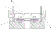
Fig. 1 is a first schematic diagram of the production mold for assembly type buildings provided by the present invention (when the movable side plate and the bottom plate enclose an inner cavity);
fig. 2 is a second schematic diagram (when the movable side plate is separated from the bottom plate) of the production mold for assembly type buildings provided by the present invention.
Reference numbers in the figures: 1. a base; 2. an inner cavity; 3. a placement chamber; 4. a base plate; 5. a movable side plate; 6. perforating; 7. an avoidance cavity; 8. a servo electric cylinder; 9. a drive motor; 10. a driving gear; 11. a driven gear; 12. a lifting screw; 13. a bearing; 14. a lifting plate; 15. pushing the push rod; 16. a large diameter guide section.
Detailed Description
In order to make the objects, technical solutions and advantages of the present invention clearer, the technical solutions of the present invention will be described in detail below. It is to be understood that the embodiments described are only some embodiments of the invention, and not all embodiments. Based on the embodiments of the present invention, all other embodiments obtained by a person skilled in the art without creative efforts belong to the protection scope of the present invention.
The present invention will be described in further detail with reference to the accompanying drawings and specific embodiments:
the utility model provides a production mould for assembly type structure's concrete embodiment:
as shown in fig. 1 and fig. 2, a production mold for assembly type building comprises a base 1, an inner cavity 2 for molding casting material and a placing cavity 3 located below the inner cavity 2 and used for placing a pushing structure, wherein the base 1 comprises a bottom plate 4 and a plurality of side plates, the bottom plate 4 surrounds the inner cavity 2, the pushing structure is provided with a pushing piece penetrating through the bottom plate 4 to enter the inner cavity 2 to push the casting material, the bottom plate 4 is provided with a through hole 6 for the pushing piece to penetrate through, at least one side plate of the plurality of side plates surrounding the inner cavity 2 is a movable side plate 5, this activity curb plate 5 and bottom plate 4 are along upper and lower direction cooperation, and the drive structure that drives activity curb plate 5 and remove along upper and lower direction still is provided with in the activity curb plate 5 outside, has the chamber 7 of dodging that supplies activity curb plate 5 to descend on the base 1, and activity curb plate 5 is used for moving down in order to relieve with the bonding of pouring material under the drive of drive structure after the shaping in inner chamber 2 of pouring material.
When the building pre-component is produced, pouring materials are poured into an inner cavity 2 of a mold, at the moment, a movable side plate 5 is in a state of enclosing the inner cavity 2 with a bottom plate 4 and other side plates, after the pouring materials are solidified and formed, the movable side plate 5 is driven to descend by a driving structure, the contact between the descending movable side plate 5 and the bonded pouring materials is relieved, so that the resistance applied when the pushing structure pushes the pouring materials upwards is reduced, then, the pushing structure is started, a pushing piece is driven by the pushing structure to penetrate through the bottom plate 4 and enter the inner cavity 2 to push the pouring materials, at the moment, the inner cavity 2 at least lacks the bonding between one movable side plate 5 and the pouring materials, the contact area between at least one movable side plate 5 and the pouring materials is reduced, the resistance applied when the pushing structure pushes the pouring materials is effectively reduced, so that the pushing structure can smoothly push the pouring materials out of the inner cavity 2, the demolding is completed, and the integrity of the casting material is better ensured.
In the present embodiment, the plurality of side plates of the base 1 for enclosing the inner cavity 2 are all movable side plates 5. The lateral direction of the pouring material is not contacted with any side plate any more and is only contacted with the bottom plate 4, so that the resistance applied when the pushing structure pushes the pouring material is greatly reduced, and the integrity of the pouring material is further ensured. In other embodiments, only one of the side plates of the base enclosing the inner cavity may be a movable side plate.
In the present embodiment, the driving mechanism is a servo electric cylinder 8. The servo electric cylinder 8 has stable rotating speed, stable operation and higher precision. In other embodiments, the drive structure may also be a pneumatic ram.
As shown in fig. 1 and 2, the pushing structure includes a driving motor 9 with an output shaft extending upward, a driving gear 10 is sleeved on the output shaft of the driving motor 9, a driven gear 11 is engaged with the outer side of the driving gear 10, a lifting screw 12 extending upward and downward is arranged in the driven gear 11, the bottom end of the lifting screw 12 is rotatably assembled on the bottom wall of the placing cavity 3 through a bearing 13, the pushing structure further includes a lifting plate 14 penetrating the lifting screw 12, a plurality of pushing rods 15 are arranged on the lifting plate 14, the pushing rods 15 form a pushing part, and the lifting plate 14 is in guiding fit with the side wall of the placing cavity 3 along the upward and downward direction. The lifting movement of the lifting plate 14 is more stable through the matching of the driving motor 9 and the lifting screw 12; the contact area of the ejector rods 15 and the pouring material is larger, the ejection effect is more stable, and the integrity of the pouring material is further ensured. Specifically, the number of the lifting screws 12 is plural, and the plurality of lifting screws 12 are uniformly arranged around the circumferential direction of the driving gear 10. In other embodiments, the number of the lifting screws can be one or two; of course, in other embodiments, the pushing structure may also include a plurality of servo electric cylinders with output ends extending upward, the output end of each servo electric cylinder is connected to the lifting plate, and the lifting plate drives the plurality of pushing rods to move upward.
As shown in fig. 1 and 2, the upper end of the ejector pin 15 has a large diameter guide section 16, and the inner diameter of the through hole 6 is matched with the outer diameter of the large diameter guide section 16. Avoiding the ejector pin 15 from being displaced in the through hole 6.
The utility model provides a production mould for assembly type structure's theory of operation is: when the building pre-component is produced, pouring materials are poured into an inner cavity 2 of a mold, at the moment, a movable side plate 5 is in a state of enclosing the inner cavity 2 with a bottom plate 4 and other side plates, after the pouring materials are solidified and formed, the movable side plate 5 is driven to descend by a driving structure, the contact between the descending movable side plate 5 and the bonded pouring materials is relieved, so that the resistance applied when the pushing structure pushes the pouring materials upwards is reduced, then, the pushing structure is started, a pushing piece is driven by the pushing structure to penetrate through the bottom plate 4 and enter the inner cavity 2 to push the pouring materials, at the moment, the inner cavity 2 at least lacks the bonding between one movable side plate 5 and the pouring materials, the contact area between at least one movable side plate 5 and the pouring materials is reduced, the resistance applied when the pushing structure pushes the pouring materials is effectively reduced, so that the pushing structure can smoothly push the pouring materials out of the inner cavity 2, the demolding is completed, the integrity of the casting material is well ensured, and the technical problem that the casting material is difficult to completely separate from the mold in the prior art so that the integrity of the casting material is poor is effectively solved.
In the present invention, unless otherwise expressly specified or limited, the terms "mounted," "connected," and "fixed" are to be construed broadly and may, for example, be fixedly connected, detachably connected, or integrally connected; can be mechanically or electrically connected; they may be connected directly or indirectly through intervening media, or they may be interconnected between two elements. The specific meaning of the above terms in the present invention can be understood according to specific situations by those skilled in the art.
The foregoing is only a preferred embodiment of the present invention, and it should be noted that, for those skilled in the art, a plurality of modifications and replacements can be made without departing from the technical principle of the present invention, and these modifications and replacements should also be regarded as the protection scope of the present invention.
Claims (6)
1. The utility model provides a production mould for assembly type structure which characterized in that: including the base, have on the base and be used for making the fashioned inner chamber of casting material and be located the chamber of placing that is used for placing the top and pushes away the structure of inner chamber below, the base is including enclosing into the bottom plate and a plurality of curb plates of inner chamber, the top pushes away the structure and has the pass the piece in order to get into the ejecting piece that pushes away the casting material of inner chamber, having the perforation that supplies the top to push away the piece and pass on the bottom plate, enclosing into at least one curb plate in a plurality of curb plates of inner chamber for movable curb plate, this movable curb plate and bottom plate along upper and lower direction cooperation, the movable curb plate outside still is provided with the drive structure that drives movable curb plate and remove from top to bottom, it supplies the descending chamber of dodging of movable curb plate to have on the base, movable curb plate is used for moving down in the drive structure after the shaping in inner chamber including casting material and removes in order to relieve with the bonding of casting material.
2. The production mold for assembly type buildings according to claim 1, characterized in that: the side plates of the base, which are used for enclosing an inner cavity, are movable side plates.
3. The production mold for assembly type buildings according to claim 1, characterized in that: the driving structure is a servo electric cylinder.
4. The production mold for prefabricated buildings according to any one of claims 1 to 3, wherein: the pushing structure comprises a driving motor with an output shaft extending upwards, a driving gear is sleeved on the output shaft of the driving motor, a driven gear is meshed outside the driving gear, a lifting screw rod extending up and down is arranged in the driven gear, the bottom end of the lifting screw rod is rotatably assembled on the bottom wall of the placing cavity through a bearing, the pushing structure further comprises a lifting plate penetrating through the lifting screw rod, a plurality of pushing rods are arranged on the lifting plate, the pushing rods form pushing pieces, and the lifting plate is in guiding fit with the side wall of the placing cavity in the up-down direction.
5. The production mold for assembly type buildings according to claim 4, wherein: the number of lifting screw rods is a plurality of, and a plurality of lifting screw rods are evenly arranged around the circumference of the driving gear.
6. The production mold for assembly type buildings according to claim 4, wherein: the upper end of the ejector rod is provided with a large-diameter guide section, and the inner diameter of the through hole is matched with the outer diameter of the large-diameter guide section.
Priority Applications (1)
| Application Number | Priority Date | Filing Date | Title |
|---|---|---|---|
| CN202120154544.9U CN214353151U (en) | 2021-01-20 | 2021-01-20 | Production mould for assembly type building |
Applications Claiming Priority (1)
| Application Number | Priority Date | Filing Date | Title |
|---|---|---|---|
| CN202120154544.9U CN214353151U (en) | 2021-01-20 | 2021-01-20 | Production mould for assembly type building |
Publications (1)
| Publication Number | Publication Date |
|---|---|
| CN214353151U true CN214353151U (en) | 2021-10-08 |
Family
ID=77957241
Family Applications (1)
| Application Number | Title | Priority Date | Filing Date |
|---|---|---|---|
| CN202120154544.9U Active CN214353151U (en) | 2021-01-20 | 2021-01-20 | Production mould for assembly type building |
Country Status (1)
| Country | Link |
|---|---|
| CN (1) | CN214353151U (en) |
Cited By (1)
| Publication number | Priority date | Publication date | Assignee | Title |
|---|---|---|---|---|
| CN115741947A (en) * | 2023-01-09 | 2023-03-07 | 常熟市江华新型建筑材料有限公司 | Road surface brick apparatus for producing that permeates water for bridge |
-
2021
- 2021-01-20 CN CN202120154544.9U patent/CN214353151U/en active Active
Cited By (1)
| Publication number | Priority date | Publication date | Assignee | Title |
|---|---|---|---|---|
| CN115741947A (en) * | 2023-01-09 | 2023-03-07 | 常熟市江华新型建筑材料有限公司 | Road surface brick apparatus for producing that permeates water for bridge |
Similar Documents
| Publication | Publication Date | Title |
|---|---|---|
| CN214442462U (en) | Stamping die is used in sheet metal component processing | |
| CN214353151U (en) | Production mould for assembly type building | |
| CN102303059A (en) | One-time molding method of gear wheel shaft | |
| CN214082424U (en) | High-precision mold for plastic gear | |
| CN110014126B (en) | Convenient ejecting ring flange mould | |
| CN210059561U (en) | Forming die for thin-wall metal product | |
| CN212072829U (en) | Mold ejection device | |
| CN210851186U (en) | Ejection mold with electric motor | |
| CN211727071U (en) | Novel elbow mould | |
| CN210061812U (en) | Plastic product mold convenient for taking out parts | |
| JP4033289B2 (en) | Forging equipment | |
| CN207642181U (en) | A kind of automobile die processing demoulding mechanism | |
| CN220636121U (en) | Pressing die for producing iron packaging barrel | |
| CN110722084A (en) | Forging and pressing die for forging sliding gear part and working method thereof | |
| CN213860537U (en) | Accurate positioning device for injection mold | |
| CN217192070U (en) | Mould convenient for quick demoulding | |
| CN111069402A (en) | Composite die for punching and trimming | |
| CN221392027U (en) | Novel motor cover injection molding die | |
| CN216544518U (en) | Novel forming die for workpiece machining | |
| CN214161093U (en) | A high efficiency stamping device for production of precision structural part | |
| CN221246941U (en) | Ignition lock core guard plate mould | |
| CN213056147U (en) | Line mould for punching heat-resistant fiber sheet | |
| CN210059801U (en) | Iron-based powder die for manufacturing eccentric ratchet wheel with shifting pin and metallurgical device | |
| CN209869314U (en) | Secondary ejection structure | |
| CN218053764U (en) | Injection mold with no overlap forming mechanism |
Legal Events
| Date | Code | Title | Description |
|---|---|---|---|
| GR01 | Patent grant | ||
| GR01 | Patent grant |