CN214337317U - Energy-saving heat-dissipation lifting type electric box - Google Patents
Energy-saving heat-dissipation lifting type electric box Download PDFInfo
- Publication number
- CN214337317U CN214337317U CN202120467147.7U CN202120467147U CN214337317U CN 214337317 U CN214337317 U CN 214337317U CN 202120467147 U CN202120467147 U CN 202120467147U CN 214337317 U CN214337317 U CN 214337317U
- Authority
- CN
- China
- Prior art keywords
- electric box
- wall
- heat
- box shell
- electronic box
- Prior art date
- Legal status (The legal status is an assumption and is not a legal conclusion. Google has not performed a legal analysis and makes no representation as to the accuracy of the status listed.)
- Active
Links
Images


Landscapes
- Cooling Or The Like Of Electrical Apparatus (AREA)
Abstract
The utility model discloses an energy-conserving heat dissipation over-and-under type electronic box, including setting up at the inside heat abstractor of electronic box casing and the elevating gear of setting in electronic box casing below, heat abstractor includes the bolt at the driving motor of electronic box casing top center inner wall, and coaxial flabellum and the drive bevel gear of blowing of having cup jointed in proper order on driving motor's the output shaft, the both sides of electronic box casing are all inserted and are equipped with the transmission shaft, and all coaxial driven bevel gear that has cup jointed on two transmission shafts, the both sides outer wall of electronic box casing has all welded the heat extraction cover, and all is equipped with in two heat extraction covers and breathes in the flabellum, two breathe in the flabellum coaxial cup joint respectively on two transmission shafts. The utility model discloses a heat abstractor and the elevating gear that set up can improve the heat dispersion of electronic box, and then can improve the work efficiency of the inside electrical components of electronic box to prolonged the life of the inside electrical components of electronic box, and the damper who sets up can improve the shock attenuation performance of electronic box.
Description
Technical Field
The utility model relates to a block terminal technical field especially relates to energy-conserving heat dissipation over-and-under type electronic box.
Background
The electric box is a distribution box, which is a mass parameter on data, generally forms a low-voltage distribution box by assembling switching equipment, measuring instruments, protective electrical appliances and auxiliary equipment in a closed or semi-closed metal cabinet or on a screen according to the electrical wiring requirement. In normal operation, the circuit can be switched on or off by means of a manual or automatic switch. The distribution box has the characteristics of small volume, simple and convenient installation, special technical performance, fixed position, unique configuration function, no field limitation, universal application, stable and reliable operation, high space utilization rate, less occupied area and environmental protection effect.
The existing electric box can not carry out lifting adjustment on the height of the box body, so that the space between the box body and the ground is smaller when the box body is internally cooled, and the heat inside the box body can not be timely discharged to the outside from the inside of the box body, so that the heat dissipation effect is poor, the working efficiency of electric elements inside the electric box is reduced, and the service life of the electric elements inside the electric box is shortened. Therefore, an energy-saving heat-dissipation lifting type electric box is provided.
SUMMERY OF THE UTILITY MODEL
The utility model aims at solving the defects existing in the prior art and providing an energy-saving heat-dissipation lifting type electric box.
In order to achieve the above purpose, the utility model adopts the following technical scheme:
an energy-saving heat dissipation lifting type electric box comprises a heat dissipation device arranged inside a shell of the electric box and a lifting device arranged below the shell of the electric box, wherein the heat dissipation device comprises a driving motor bolted on the inner wall of the center of the top of the shell of the electric box, an air blowing fan blade and a driving bevel gear are sequentially and coaxially sleeved on an output shaft of the driving motor, transmission shafts are inserted on two sides of the shell of the electric box, driven bevel gears are coaxially sleeved on the two transmission shafts, heat dissipation covers are welded on the outer walls of two sides of the shell of the electric box, air suction fan blades are arranged in the two heat dissipation covers, the two air suction fan blades are respectively and coaxially sleeved on the two transmission shafts, a through hole is formed in the inner wall of the top of the shell of the electric box, two heat absorption holes are formed in the inner walls of two sides of the shell of the electric box, a heat dissipation hole is formed in the inner wall of one side, far away from each other heat dissipation cover, two inner walls of the bottom of the shell of the electric box are formed in the bottom of the shell of the electric box, the lifting device comprises a base, a mounting groove is formed in the inner wall of the top of the base, a motor bin is bolted on the side wall of the base, a servo motor is bolted on the inner wall of one side of the motor bin, an output shaft of the servo motor is connected with a bidirectional screw rod through a coupler, two threaded sleeves are installed on the bidirectional screw rod in a threaded manner, reinforcing ribs are hinged to the tops of the two threaded sleeves, the top ends of the two reinforcing ribs are hinged to the bottom of the electric box shell, a limiting groove is formed in the inner wall of the bottom of the mounting groove, two limiting rods are welded on the outer wall of the bottom of the two threaded sleeves, the outer walls of the bottoms of the two limiting rods are connected with the inner wall of the bottom of the limiting groove in a sliding manner, a damping mechanism is arranged in the base and comprises damping grooves formed in the inner wall of the bottom of the base, damping springs distributed at equal intervals are welded on the inner wall of the top of the damping grooves, and the outer wall welding of a plurality of damping spring's bottom has same antiskid ribbed tile.
Preferably, the two driven bevel gears are meshed with the driving bevel gear, the two transmission shafts are respectively connected with the inner walls of the two sides of the electric box shell through bearings, and dust screens are bolted in the through hole, the heat absorption hole, the heat exhaust hole and the heat dissipation hole.
Preferably, the two-way screw rod is respectively connected with the inner walls of the two sides of the mounting groove through two bearings, and the two threaded sleeves are respectively installed at two opposite threaded ends of the two-way screw rod in a threaded manner.
Preferably, the servo motor is connected with a reversing switch through a wire, and the reversing switch is connected with a power line.
Preferably, the rain shed is welded on the outer wall of the top of the electric box shell, the outer wall of the front face of the electric box shell is hinged to a box door through hinges distributed equidistantly, and anti-slip lines distributed equidistantly are arranged on the outer wall of the bottom of the anti-slip plate.
Preferably, two the strengthening rib is the slope setting, and two strengthening ribs are bilateral symmetry and distribute based on the bottom central point of electronic box casing puts.
The utility model has the advantages that:
1. through the arranged heat dissipation device, the driving motor drives the air blowing fan blades and the driving bevel gear to rotate simultaneously, then the two driven bevel gears meshed with the driving bevel gear drive the two transmission shafts to rotate, and finally the two air suction fan blades also rotate;
2. through the arranged lifting device, when heat dissipation is carried out, the bidirectional screw rod is driven to rotate forwards or reversely through the servo motor, the two threaded sleeves are close to or far away from each other under the limiting action of the two limiting rods and the limiting grooves, and finally the electric box shell can be lifted under the hinging action of the two obliquely arranged reinforcing ribs, so that heat inside the box body can be timely discharged to the outside from the inside of the box body, the heat dissipation effect is further improved, and the electric box can be adapted to workers with different heights to carry out maintenance work through lifting of the electric box;
3. in summary, the following steps: the utility model discloses a heat abstractor and the elevating gear that set up can improve the heat dispersion of electronic box, and then can improve the work efficiency of the inside electrical components of electronic box to prolonged the life of the inside electrical components of electronic box, and the damper who sets up can improve the shock attenuation performance of electronic box.
Drawings
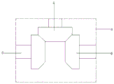
Fig. 1 is a schematic structural view of an energy-saving heat-dissipating lifting type electrical box provided by the present invention;
fig. 2 is a schematic front view of the energy-saving heat-dissipating lifting electrical box of the present invention;
fig. 3 is an enlarged schematic view of a portion a in fig. 2.
In the figure: the device comprises an electric box shell 1, a driving motor 2, an air blowing fan blade 3, a driving bevel gear 4, a transmission shaft 5, a driven bevel gear 6, a heat exhaust cover 7, an air suction fan blade 8, a through hole 9, a heat exhaust hole 10, a heat exhaust hole 11, a heat dissipation hole 12, a base 13, a motor cabin 14, a servo motor 15, a bidirectional screw rod 16, a threaded sleeve 17, a reinforcing rib 18, a limiting groove 19, a limiting rod 20, a damping groove 21, a damping spring 22, an antiskid plate 23, a rain shelter 24 and a box door 25.
Detailed Description
The technical solutions in the embodiments of the present invention will be described clearly and completely with reference to the accompanying drawings in the embodiments of the present invention, and it is obvious that the described embodiments are only some embodiments of the present invention, not all embodiments.
Referring to fig. 1-3, an energy-saving heat dissipation lifting type electrical box comprises a heat dissipation device arranged inside an electrical box shell 1 and a lifting device arranged below the electrical box shell 1, wherein the heat dissipation device comprises a driving motor 2 bolted to the inner wall of the center of the top of the electrical box shell 1, an air blowing fan blade 3 and a driving bevel gear 4 are sequentially and coaxially sleeved on an output shaft of the driving motor 2, transmission shafts 5 are respectively inserted on two sides of the electrical box shell 1, driven bevel gears 6 are respectively and coaxially sleeved on the two transmission shafts 5, heat exhaust covers 7 are respectively welded on the outer walls of two sides of the electrical box shell 1, air suction fan blades 8 are respectively arranged in the two heat exhaust covers 7, the two air suction fan blades 8 are respectively and coaxially sleeved on the two transmission shafts 5, a through hole 9 is arranged on the inner wall of the top of the electrical box shell 1, two heat exhaust holes 10 are respectively arranged on the inner walls of two sides of the electrical box shell 1, and a heat exhaust hole 11 is arranged on the inner wall of one side, which the two heat exhaust covers 7 are far away from each other, two heat dissipation holes 12 are formed in the inner wall of the bottom of an electric box shell 1, two driven bevel gears 6 are meshed with a driving bevel gear 4, two transmission shafts 5 are connected with the inner walls of two sides of the electric box shell 1 through bearings respectively, dust screens are bolted in through holes 9, heat absorption holes 10, heat extraction holes 11 and the heat dissipation holes 12, a driving motor 2 drives an air blowing fan blade 3 and the driving bevel gear 4 to rotate simultaneously through a set heat dissipation device, then the two driven bevel gears 6 meshed with the driving bevel gear 4 drive the two transmission shafts 5 to rotate, and finally the two air suction fan blades 8 also rotate, so that the combination of air blowing and air blowing modes is adopted, the heat dissipation effect of the electric box is better, no redundant driving source is needed to be arranged, the use cost can be reduced, the electric power resource is saved, and the energy-saving effect is achieved;
the lifting device comprises a base 13, a mounting groove is formed in the inner wall of the top of the base 13, a motor bin 14 is bolted on the side wall of the base 13, a servo motor 15 is bolted on the inner wall of one side of the motor bin 14, the servo motor 15 is connected with a reversing switch through a lead, the reversing switch is connected with a power cord, an output shaft of the servo motor 15 is connected with a bidirectional screw 16 through a coupler, two threaded sleeves 17 are mounted on the bidirectional screw 16 in a threaded manner, reinforcing ribs 18 are hinged to the tops of the two threaded sleeves 17, the top ends of the two reinforcing ribs 18 are hinged to the bottom of the electric box shell 1, a limiting groove 19 is formed in the inner wall of the bottom of the mounting groove, two limiting rods 20 are welded on the outer wall of the bottom of the two threaded sleeves 17, the outer walls of the bottom ends of the two limiting rods 20 are connected with the inner wall of the bottom of the limiting groove 19 in a sliding manner, and the bidirectional screw 16 is respectively connected with the inner walls of two sides of the mounting groove through two bearings, the two threaded sleeves 17 are respectively installed at two opposite threaded ends of the bidirectional screw 16 in a threaded manner, the two reinforcing ribs 18 are obliquely arranged, the two reinforcing ribs 18 are symmetrically distributed on the left and right based on the bottom center position of the electric box shell 1, a damping mechanism is arranged in the base 13 and comprises a damping groove 21 arranged on the inner wall of the bottom of the base 13, damping springs 22 distributed at equal intervals are welded on the inner wall of the top of the damping groove 21, the outer walls of the bottom ends of the damping springs 22 are welded with a same antiskid plate 23, a rain shelter 24 is welded on the outer wall of the top of the electric box shell 1, the outer wall of the front surface of the electric box shell 1 is hinged with a box door 25 through hinges distributed at equal intervals, antiskid grains distributed at equal intervals are arranged on the outer wall of the bottom of the antiskid plate 23, and the bidirectional screw 16 is driven to rotate forwards or reversely through the servo motor 15 during heat dissipation through the arranged lifting device, under the spacing of two gag lever posts 20 and spacing groove 19, two threaded sleeve 17 are close to each other or keep away from, set up under the articulated effect of strengthening rib 18 in two slopes, finally electronic box casing 1 can realize going up and down, the inside heat of box can be timely arrange to the external world from the box inside like this, further improve the radiating effect, and through the lift of electronic box, can also adapt to the staff of different heights and maintain the work, the damper who sets up can improve the damping performance of electronic box.
The working principle is as follows: when heat dissipation is needed in the electric box, a driving motor 2 and a servo motor 15 are started, the driving motor 2 drives an air blowing fan blade 3 and a driving bevel gear 4 to rotate simultaneously, then two driven bevel gears 6 meshed with the driving bevel gear 4 drive two transmission shafts 5 to rotate, finally two air suction fan blades 8 also rotate, so that the air blowing fan blade 3 and a through hole 9 form air convection to generate air negative pressure, hot air in the electric box shell 1 is blown to the outside from two heat dissipation holes 12, the two air suction fan blades 8 and two heat dissipation holes 11 form air convection to generate air negative pressure, the hot air in the electric box shell 1 is sucked into two heat dissipation covers 7 from a heat absorption hole 10, finally the hot air is discharged to the outside from the two heat dissipation holes 11, and during heat dissipation, a bidirectional screw 16 is driven to rotate forwards or reversely by the servo motor 15, under the limit of two limit rods 20 and a limit groove 19, two threaded sleeve 17 are close to each other or keep away from, set up under the articulated effect of strengthening rib 18 in two slopes, and finally electronic box casing 1 can realize going up and down, and the inside heat of box can be timely arrange to the external world from the box is inside like this, further improves the radiating effect, realizes the shock attenuation effect through damping spring 22's cushioning effect, can prevent to a certain extent that external dust from entering into electronic box casing 1's inside through the dust screen.
In the description of the present invention, it is to be understood that the terms "center", "longitudinal", "lateral", "length", "width", "thickness", "upper", "lower", "front", "rear", "left", "right", "vertical", "horizontal", "top", "bottom", "inner", "outer", "clockwise", "counterclockwise", and the like indicate orientations or positional relationships based on the orientations or positional relationships shown in the drawings, and are only for convenience of description and to simplify the description, but do not indicate or imply that the device or element referred to must have a particular orientation, be constructed and operated in a particular orientation, and therefore should not be construed as limiting the present invention.
Furthermore, the terms "first", "second" and "first" are used for descriptive purposes only and are not to be construed as indicating or implying relative importance or implicitly indicating the number of technical features indicated. Thus, a feature defined as "first" or "second" may explicitly or implicitly include one or more of that feature. In the description of the present invention, "a plurality" means two or more unless specifically limited otherwise.
The above, only be the concrete implementation of the preferred embodiment of the present invention, but the protection scope of the present invention is not limited thereto, and any person skilled in the art is in the technical scope of the present invention, according to the technical solution of the present invention and the utility model, the concept of which is equivalent to replace or change, should be covered within the protection scope of the present invention.
Claims (6)
1. The energy-saving heat-dissipation lifting type electric box comprises a heat dissipation device arranged inside an electric box shell (1) and a lifting device arranged below the electric box shell (1), and is characterized in that the heat dissipation device comprises a driving motor (2) bolted on the inner wall of the center of the top of the electric box shell (1), an air blowing fan blade (3) and a driving bevel gear (4) are sequentially and coaxially sleeved on an output shaft of the driving motor (2), transmission shafts (5) are inserted into two sides of the electric box shell (1), driven bevel gears (6) are coaxially sleeved on the two transmission shafts (5), heat exhaust covers (7) are welded on the outer walls of two sides of the electric box shell (1), air suction fan blades (8) are arranged in the two heat exhaust covers (7), the two air suction fan blades (8) are respectively and coaxially sleeved on the two transmission shafts (5), a through hole (9) is formed in the inner wall of the top of the electric box shell (1), and the inner walls of the two sides of the electric box shell (1) are respectively provided with two heat absorption holes (10), the inner wall of one side, away from each other, of the two heat extraction covers (7) is respectively provided with a heat extraction hole (11), the inner wall of the bottom of the electric box shell (1) is provided with two heat dissipation holes (12), the lifting device comprises a base (13), the inner wall of the top of the base (13) is provided with a mounting groove, the side wall of the base (13) is bolted with a motor bin (14), the inner wall of one side of the motor bin (14) is bolted with a servo motor (15), the output shaft of the servo motor (15) is connected with a bidirectional screw rod (16) through a coupler, two threaded sleeves (17) are arranged on the bidirectional screw rod (16) in a threaded manner, the tops of the two threaded sleeves (17) are respectively hinged with a reinforcing rib (18), and the top ends of the two reinforcing ribs (18) are respectively hinged to the bottom of the electric box shell (1), spacing groove (19) have been seted up to the bottom inner wall of mounting groove, and the bottom outer wall welding of two threaded sleeve (17) has two gag lever post (20), two the bottom outer wall of gag lever post (20) all with the bottom inner wall sliding connection of spacing groove (19), be equipped with damper in base (13), and damper is including seting up damping groove (21) at base (13) bottom inner wall, the top inner wall welding of damping groove (21) has damping spring (22) that the equidistance distributes, and the bottom outer wall welding of a plurality of damping spring (22) has same antiskid ribbed tile (23).
2. The energy-saving heat-dissipation lifting type electric box according to claim 1, wherein two driven bevel gears (6) are meshed with the driving bevel gear (4), two transmission shafts (5) are respectively connected with the inner walls of two sides of the electric box shell (1) through bearings, and dust screens are bolted in the through hole (9), the heat absorption hole (10), the heat exhaust hole (11) and the heat dissipation holes (12).
3. The energy-saving heat-dissipation lifting type electric box according to claim 1, wherein the bidirectional screw (16) is respectively connected with the inner walls of two sides of the installation groove through two bearings, and two threaded sleeves (17) are respectively and threadedly installed at two opposite threaded ends of the bidirectional screw (16).
4. The energy-saving heat-dissipation lifting type electric box according to claim 1, wherein the servo motor (15) is connected with a reversing switch through a lead, and the reversing switch is connected with a power line.
5. The energy-saving heat-dissipation lifting type electric box according to claim 1, wherein a rain shelter (24) is welded on the outer wall of the top of the electric box shell (1), the outer wall of the front face of the electric box shell (1) is hinged to a box door (25) through hinges distributed at equal intervals, and the outer wall of the bottom of the antiskid plate (23) is provided with antiskid grains distributed at equal intervals.
6. The energy-saving heat-dissipation lifting type electric box according to claim 1, wherein the two reinforcing ribs (18) are obliquely arranged, and the two reinforcing ribs (18) are symmetrically distributed left and right based on the central position of the bottom of the electric box shell (1).
Priority Applications (1)
| Application Number | Priority Date | Filing Date | Title |
|---|---|---|---|
| CN202120467147.7U CN214337317U (en) | 2021-03-04 | 2021-03-04 | Energy-saving heat-dissipation lifting type electric box |
Applications Claiming Priority (1)
| Application Number | Priority Date | Filing Date | Title |
|---|---|---|---|
| CN202120467147.7U CN214337317U (en) | 2021-03-04 | 2021-03-04 | Energy-saving heat-dissipation lifting type electric box |
Publications (1)
| Publication Number | Publication Date |
|---|---|
| CN214337317U true CN214337317U (en) | 2021-10-01 |
Family
ID=77887831
Family Applications (1)
| Application Number | Title | Priority Date | Filing Date |
|---|---|---|---|
| CN202120467147.7U Active CN214337317U (en) | 2021-03-04 | 2021-03-04 | Energy-saving heat-dissipation lifting type electric box |
Country Status (1)
| Country | Link |
|---|---|
| CN (1) | CN214337317U (en) |
Cited By (1)
| Publication number | Priority date | Publication date | Assignee | Title |
|---|---|---|---|---|
| CN116389871A (en) * | 2023-04-10 | 2023-07-04 | 浙江禾十平安全装备有限公司 | Intelligent security camera with expansion heat dissipation mechanism |
-
2021
- 2021-03-04 CN CN202120467147.7U patent/CN214337317U/en active Active
Cited By (2)
| Publication number | Priority date | Publication date | Assignee | Title |
|---|---|---|---|---|
| CN116389871A (en) * | 2023-04-10 | 2023-07-04 | 浙江禾十平安全装备有限公司 | Intelligent security camera with expansion heat dissipation mechanism |
| CN116389871B (en) * | 2023-04-10 | 2024-01-30 | 深圳市弘美达科技有限公司 | Intelligent security camera with expansion heat dissipation mechanism |
Similar Documents
| Publication | Publication Date | Title |
|---|---|---|
| CN108847598A (en) | A kind of distribution box with multi-faceted wind-blowing heat-dissipating function | |
| CN214337317U (en) | Energy-saving heat-dissipation lifting type electric box | |
| CN107579440A (en) | A kind of outdoor multifunction power cabinet of power engineering | |
| CN214945175U (en) | Heat dissipation mounting bracket based on air conditioner computer board control structure | |
| CN214014823U (en) | Communication equipment box | |
| CN215934124U (en) | Power distribution cabinet based on internet remote control | |
| CN211480531U (en) | Novel electric wire netting electric power cabinet | |
| CN212968757U (en) | Intelligent comprehensive distribution transformer distribution box | |
| CN211579293U (en) | Power equipment heat abstractor for communication engineering | |
| CN210201284U (en) | Switch board with dust removal and heat radiation structure | |
| CN220254110U (en) | High-strength low-voltage junction box | |
| CN221428401U (en) | Outdoor ventilation heat dissipation type electrical control cabinet | |
| CN213043273U (en) | Convenient electric control cabinet that removes | |
| CN219643323U (en) | Alternating-current low-voltage power distribution cabinet | |
| CN214153706U (en) | Low-voltage power distribution device | |
| CN215955828U (en) | Electrical equipment switch cabinet with power utilization identification function | |
| CN220754153U (en) | Modularized power distribution cabinet beneficial to updating and maintenance | |
| CN217984204U (en) | High-efficient radiating electrical equipment dustproof protection case | |
| CN213243305U (en) | Novel assembled switch board | |
| CN213341229U (en) | Motor control cabinet with heat radiation structure | |
| CN209768107U (en) | Electric information automatic control device based on electronic information pump station | |
| CN217656844U (en) | Control cabinet with energy-saving heat dissipation structure | |
| CN218513914U (en) | Outdoor high temperature resistance control block terminal | |
| CN215119758U (en) | Combined control cabinet | |
| CN116404542B (en) | High-voltage cabinet convenient to maintain and used for wind power generation booster station and use method |
Legal Events
| Date | Code | Title | Description |
|---|---|---|---|
| GR01 | Patent grant | ||
| GR01 | Patent grant |