CN214330194U - Safety isolation guardrail for construction - Google Patents
Safety isolation guardrail for construction Download PDFInfo
- Publication number
- CN214330194U CN214330194U CN202120017925.2U CN202120017925U CN214330194U CN 214330194 U CN214330194 U CN 214330194U CN 202120017925 U CN202120017925 U CN 202120017925U CN 214330194 U CN214330194 U CN 214330194U
- Authority
- CN
- China
- Prior art keywords
- fixedly connected
- guardrail
- block
- safety isolation
- rail
- Prior art date
- Legal status (The legal status is an assumption and is not a legal conclusion. Google has not performed a legal analysis and makes no representation as to the accuracy of the status listed.)
- Active
Links
Images


Abstract
The utility model belongs to the technical field of isolation guardrails, in particular to a safety isolation guardrail for building construction, which comprises a base, wherein the top of the base is fixedly connected with a stand column, one side of the stand column is fixedly connected with a first rail, one side of the stand column is fixedly connected with a second rail, the top of the first rail is fixedly connected with a limiting block, and the inner wall of the limiting block is movably connected with a fixed block, the pedestrian and vehicle warning device can better warn passing pedestrians and vehicles.
Description
Technical Field
The utility model relates to an isolation barrier technical field specifically is a safety isolation guardrail for construction.
Background
With the advance of modern technology, the building industry is rapidly developed, so that more and more high buildings are pulled out, but for the safety of building personnel and pedestrians outside, an isolation fence is installed at the periphery of a construction site to ensure the smooth advance of building construction, but the following problems still exist in the prior art:
1. most of the isolation fences on the construction site have single structures and poor safety performance, and when an outside vehicle is accidentally impacted, the isolation fences are easily destroyed and accidental injuries are caused;
2. the existing isolation guardrail for the construction site is basically of an integral structure, is relatively complex when being assembled and disassembled by workers and is inconvenient to carry.
SUMMERY OF THE UTILITY MODEL
Technical problem to be solved
Aiming at the defects of the prior art, the utility model provides a safety isolation guardrail for building construction, which solves the problems that most isolation guardrails on construction sites have single structure and poor safety performance, and the isolation guardrails are easy to destroy and cause accidental injury when the outside vehicle is accidentally impacted; the existing isolation guardrail for the construction site is basically of an integral structure, is more complicated when being assembled and disassembled by workers and has the problem of inconvenient carrying.
(II) technical scheme
In order to achieve the above object, the utility model provides a following technical scheme: a safety isolation guardrail for building construction comprises a base, wherein the top of the base is fixedly connected with an upright column, one side of the upright column is fixedly connected with a first rail, one side of the upright column is fixedly connected with a second rail, the top of the first rail is fixedly connected with a limiting block, the inner wall of the limiting block is movably connected with a fixed block, the top of the fixed block is fixedly connected with a guardrail frame, the inner wall of the guardrail frame is fixedly connected with guardrail nets, one side of the two guardrail nets is fixedly connected with a telescopic rod, the top of the guardrail frame is fixedly connected with a connecting rod, the top of the connecting rod is fixedly connected with an I-shaped block, the surface of the I-shaped block is provided with a clamping groove, the inner wall of the clamping groove is fixedly connected with a second spring, one end of the second spring is fixedly connected with a connecting block, the surface of the connecting block is slidably connected with a U-shaped block, and the top of the U-shaped block is fixedly connected with a supporting column, the top fixedly connected with second horizontal bar of support column, the surface of stand is rotated through the bearing and is connected with the sleeve, telescopic one side fixedly connected with L shape pole, one side swing joint of L shape pole has the fixed orifices, the top fixedly connected with spliced pole of stand, the top fixedly connected with warning light of spliced pole.
As an optimized technical scheme of the utility model, the through-hole has been seted up on the both sides surface of U-shaped piece, the surface and the through-hole of connecting block laminate mutually.
As an optimal technical scheme of the utility model, the surperficial sliding connection of telescopic link has first spring, the tip fixed connection guardrail net of first spring.
As an optimized technical scheme of the utility model, one side fixedly connected with handle of guardrail frame, the surface of handle is equipped with the antiskid cover.
As an optimal technical scheme of the utility model, the fixed surface of spliced pole is connected with reflection of light strip, reflection of light strip is equidistant distribution on the surface of spliced pole.
As an optimized technical scheme of the utility model, the quantity of fixed orifices is two, the fixed orifices is half arc shape.
(III) advantageous effects
Compared with the prior art, the utility model provides a safety isolation guardrail for construction possesses following beneficial effect:
1. this safety isolation guardrail for construction, through at two-layer guardrail net of guardrail frame inner wall installation, through connecting the telescopic link in two-layer guardrail net, through at the first spring of telescopic link outer wall connection, can play the cushioning effect when hitting on the isolation net if peripheral vehicle accident, reduce unexpected injury, through at spliced pole surface mounting reflection of light strip, can reflect light when light is not enough, remind pedestrian here to have the isolation guardrail, through setting up the warning light at the spliced pole top, can be better play the warning effect to passing pedestrian and vehicle.
2. This safety isolation guardrail for construction through the top installation stopper at first horizontal bar, through staff's extrusion connecting block, the connecting block can extrude the second spring at the motion of draw-in groove inner wall, through rotating L shape pole, connects L shape pole and fixed orifices, makes things convenient for the staff to the equipment and the dismantlement of guardrail frame when the construction.
Drawings
FIG. 1 is a schematic structural view of the present invention;
FIG. 2 is a top view of the safety isolation balustrade of the present invention;
FIG. 3 is a structural sectional view of a U-shaped block of the present invention;
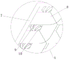
fig. 4 is an enlarged view of the area a in fig. 2 according to the present invention.
In the figure: 1. a base; 2. a column; 3. a first rail; 4. a second rail; 5. a limiting block; 6. a fixed block; 7. a guardrail frame; 8. a barrier net; 9. a telescopic rod; 10. a first spring; 11. a connecting rod; 12. a H-shaped block; 13. a card slot; 14. a second spring; 15. connecting blocks; 16. a U-shaped block; 17. a support pillar; 18. a sleeve; 19. an L-shaped rod; 20. a fixing hole; 21. a handle; 22. connecting columns; 23. a warning light; 24. a reflective strip.
Detailed Description
The technical solutions in the embodiments of the present invention will be described clearly and completely with reference to the accompanying drawings in the embodiments of the present invention, and it is obvious that the described embodiments are only some embodiments of the present invention, not all embodiments. Based on the embodiments in the present invention, all other embodiments obtained by a person skilled in the art without creative work belong to the protection scope of the present invention.
Examples
Referring to fig. 1-4, the present invention provides the following technical solutions: a safety isolation guardrail for building construction comprises a base 1, wherein the top of the base 1 is fixedly connected with an upright post 2, one side of the upright post 2 is fixedly connected with a first rail 3, one side of the upright post 2 is fixedly connected with a second rail 4, the top of the first rail 3 is fixedly connected with a limiting block 5, the inner wall of the limiting block 5 is movably connected with a fixed block 6, the top of the fixed block 6 is fixedly connected with a guardrail frame 7, the inner wall of the guardrail frame 7 is fixedly connected with guardrail nets 8, one side of the two guardrail nets 8 is fixedly connected with a telescopic rod 9, the top of the guardrail frame 7 is fixedly connected with a connecting rod 11, the top of the connecting rod 11 is fixedly connected with an I-shaped block 12, the surface of the I-shaped block 12 is provided with a clamping groove 13, the inner wall of the clamping groove 13 is fixedly connected with a second spring 14, one end of the second spring 14 is fixedly connected with a connecting block 15, the surface of the connecting block 15 is slidably connected with a U16, and the top of the U-shaped block 16 is fixedly connected with a supporting column 17, top fixedly connected with second horizontal bar 4 of support column 17, the surface of stand 2 is connected with sleeve 18 through the bearing rotation, one side fixedly connected with L shape pole 19 of sleeve 18, one side swing joint of L shape pole 19 has fixed orifices 20, the top fixedly connected with spliced pole 22 of stand 2, the top fixedly connected with warning light 23 of spliced pole 22.
In this embodiment, two layers of guardrail nets 8 are installed on the inner wall of the guardrail frame 7, the telescopic rod 9 is connected inside the guardrail net 8, the first spring 10 is connected on the surface of the telescopic rod 9, the impact object can be buffered, the damage to a certain degree is reduced, the limiting block 5 and the fixed block 6 are installed on the top of the first rail 3 for limiting, so that the bottom of the guardrail frame 7 is fixed, the connecting rod 11 is connected on the top of the guardrail frame 7, the I-shaped block 12 is connected on the top of the connecting rod 11, the second spring 14 is driven to move inside the clamping groove 13 by extruding the connecting block 15, so that the connecting block 15 is attached to the through hole formed on the two sides of the U-shaped block 16, the handle 21 is installed on the two sides of the guardrail frame 7, the worker can disassemble the guardrail frame 7 by the handle 21, the sleeve 18 is connected on the surface of the upright post 2, the L-shaped rod 19 is driven to rotate by the sleeve 18, the L-shaped rod 19 is connected with the fixing hole 20, so that the guardrail frame 7 is fixed.
Specifically, through holes are formed in the surfaces of the two sides of the U-shaped block 16, and the surface of the connecting block 15 is attached to the through holes.
In this embodiment, the top of the guardrail frame 7 can be assembled and disassembled by inserting the connecting block 15 into the through hole of the U-shaped block 16.
Specifically, the surface of the telescopic rod 9 is connected with a first spring 10 in a sliding manner, and the end part of the first spring 10 is fixedly connected with the guardrail net 8.
In this embodiment, two layers of barrier nets 8 are arranged, and the first spring 10 is installed inside, so that the impact on the object can be buffered.
Specifically, one side of the guardrail frame 7 is fixedly connected with a handle 21, and the surface of the handle 21 is provided with an anti-skid sleeve.
In this embodiment, through the setting of handle 21, make things convenient for the staff to install guardrail frame 7.
Specifically, the surface of the connecting column 22 is fixedly connected with the reflective strips 24, and the reflective strips 24 are distributed on the surface of the connecting column 22 at equal intervals.
In this embodiment, through the reflection of light effect of reflection of light strip 24, can remind the pedestrian here to have the construction site when light is not enough.
Specifically, the number of the fixing holes 20 is two, and the fixing holes 20 are half arc-shaped.
In this embodiment, the fixing of the fence frame 7 can be enhanced by rotating the L-shaped rod 19 to connect with the fixing hole 20.
The utility model discloses a theory of operation and use flow: the guardrail main body can be fixed by connecting the upright post 2 at the top of the base 1, connecting the first rail 3 at the bottom of one side of the upright post 2, connecting the second rail 4 at the top of one side of the upright post 2, connecting the limiting block 5 at the top of the first rail 3, connecting the fixing block 6 through the inner wall of the limiting block 5, connecting the guardrail frame 7 at the top of the fixing block 6, limiting and fixing the bottom of the guardrail frame 7, installing two layers of guardrail nets 8 on the inner wall of the guardrail frame 7, connecting the telescopic rods 9 inside the guardrail nets 8, connecting the first springs 10 on the surfaces of the telescopic rods 9, playing a role of buffering the external impact object and reducing damage to a certain degree, connecting the connecting rod 11 at the top of the guardrail frame 7, connecting the block 12 at the top of the connecting rod 11, and driving the second springs 14 to move inside the clamping grooves 13 by extruding the connecting block 15, make the through-hole that connecting block 15 and U-shaped piece 16 both sides were seted up laminate mutually, through at guardrail frame 7 both sides installation handle 21, the staff can hand handle 21 and assemble and dismantle the top of guardrail frame 7, through at stand 2 surface connection sleeve 18, drive L shape pole 19 through sleeve 18 and rotate can with 20 swing joint of fixed orifices of guardrail frame 7 one side, the effect of fixing has been played guardrail frame 7, through connecting warning light 23 at the top of spliced pole 22, through set up anti-light strip 24 on the surface at spliced pole 22, can play the warning effect to passing vehicle and pedestrian evening.
Finally, it should be noted that: although the present invention has been described in detail with reference to the foregoing embodiments, it will be apparent to those skilled in the art that modifications may be made to the embodiments described in the foregoing embodiments, or equivalents may be substituted for elements thereof. Any modification, equivalent replacement, or improvement made within the spirit and principle of the present invention should be included in the protection scope of the present invention.
Claims (6)
1. The utility model provides a safety isolation guardrail for construction, includes base (1), its characterized in that: the guardrail comprises a base (1), a stand column (2) is fixedly connected to the top of the base (1), a first rail (3) is fixedly connected to one side of the stand column (2), a second rail (4) is fixedly connected to one side of the stand column (2), a limiting block (5) is fixedly connected to the top of the first rail (3), a fixing block (6) is movably connected to the inner wall of the limiting block (5), a guardrail frame (7) is fixedly connected to the top of the fixing block (6), a guardrail net (8) is fixedly connected to the inner wall of the guardrail frame (7), telescopic rods (9) are fixedly connected to one sides of the two guardrail nets (8), a connecting rod (11) is fixedly connected to the top of the guardrail frame (7), an I-shaped block (12) is fixedly connected to the top of the connecting rod (11), a clamping groove (13) is formed in the surface of the I-shaped block (12), and a second spring (14) is fixedly connected to the inner wall of the clamping groove (13), the one end fixedly connected with connecting block (15) of second spring (14), the surperficial sliding connection of connecting block (15) has U-shaped piece (16), the top fixedly connected with support column (17) of U-shaped piece (16), top fixedly connected with second horizontal bar (4) of support column (17), the surface of stand (2) is rotated through the bearing and is connected with sleeve (18), one side fixedly connected with L shape pole (19) of sleeve (18), one side swing joint of L shape pole (19) has fixed orifices (20), the top fixedly connected with spliced pole (22) of stand (2), the top fixedly connected with warning light (23) of spliced pole (22).
2. The safety isolation barrier for building construction according to claim 1, wherein: through holes are formed in the surfaces of the two sides of the U-shaped block (16), and the surface of the connecting block (15) is attached to the through holes.
3. The safety isolation barrier for building construction according to claim 1, wherein: the surface of the telescopic rod (9) is connected with a first spring (10) in a sliding mode, and the end portion of the first spring (10) is fixedly connected with a guardrail net (8).
4. The safety isolation barrier for building construction according to claim 1, wherein: one side of the guardrail frame (7) is fixedly connected with a handle (21), and the surface of the handle (21) is provided with an anti-skidding sleeve.
5. The safety isolation barrier for building construction according to claim 1, wherein: the surface of the connecting column (22) is fixedly connected with light reflecting strips (24), and the light reflecting strips (24) are distributed on the surface of the connecting column (22) at equal intervals.
6. The safety isolation barrier for building construction according to claim 1, wherein: the number of the fixing holes (20) is two, and the fixing holes (20) are in a half-arc shape.
Priority Applications (1)
| Application Number | Priority Date | Filing Date | Title |
|---|---|---|---|
| CN202120017925.2U CN214330194U (en) | 2021-01-05 | 2021-01-05 | Safety isolation guardrail for construction |
Applications Claiming Priority (1)
| Application Number | Priority Date | Filing Date | Title |
|---|---|---|---|
| CN202120017925.2U CN214330194U (en) | 2021-01-05 | 2021-01-05 | Safety isolation guardrail for construction |
Publications (1)
| Publication Number | Publication Date |
|---|---|
| CN214330194U true CN214330194U (en) | 2021-10-01 |
Family
ID=77905130
Family Applications (1)
| Application Number | Title | Priority Date | Filing Date |
|---|---|---|---|
| CN202120017925.2U Active CN214330194U (en) | 2021-01-05 | 2021-01-05 | Safety isolation guardrail for construction |
Country Status (1)
| Country | Link |
|---|---|
| CN (1) | CN214330194U (en) |
-
2021
- 2021-01-05 CN CN202120017925.2U patent/CN214330194U/en active Active
Similar Documents
| Publication | Publication Date | Title |
|---|---|---|
| CN210163829U (en) | Guardrail convenient to equipment and dismantlement | |
| CN108643091A (en) | Traffic route airbag restraint column device | |
| CN214330194U (en) | Safety isolation guardrail for construction | |
| CN212956275U (en) | Novel guardrail can be dismantled to road bridge engineering | |
| CN210439137U (en) | Long-connected anti-collision equipment for highway bridge | |
| CN212052490U (en) | Traffic guardrail with traffic sign | |
| CN214943127U (en) | Safety protection rail for highway construction | |
| CN215485192U (en) | Safety barrier that construction was used | |
| CN212027382U (en) | Electric power construction rail guard | |
| CN212714693U (en) | Road and bridge rail guard with adjustable | |
| CN219808261U (en) | Combined road and bridge guardrail | |
| CN219240383U (en) | Highway bridge rail guard | |
| CN214301434U (en) | Novel building engineering rail guard | |
| CN211114927U (en) | Special guardrail of civil engineering | |
| CN220100879U (en) | Rail guard with warning function | |
| CN215441631U (en) | Rail guard structure convenient to equipment on both sides of road | |
| CN219548602U (en) | Can early warning face limit guard rail | |
| CN210827238U (en) | Buffering highway guardrail | |
| CN215212709U (en) | A security fence for building engineering construction safety | |
| CN218204079U (en) | Road guardrail anti-block | |
| CN218581317U (en) | Rail guard for building safety | |
| CN219061217U (en) | Guardrail for road construction | |
| CN216475050U (en) | Novel foundation pit safety protection device for municipal road engineering | |
| CN211173370U (en) | Highway bridge construction foundation ditch protector | |
| CN220117902U (en) | Deep foundation pit support structure |
Legal Events
| Date | Code | Title | Description |
|---|---|---|---|
| GR01 | Patent grant | ||
| GR01 | Patent grant |