CN214310800U - Permanent magnet synchronous motor load test tool - Google Patents
Permanent magnet synchronous motor load test tool Download PDFInfo
- Publication number
- CN214310800U CN214310800U CN202023254447.1U CN202023254447U CN214310800U CN 214310800 U CN214310800 U CN 214310800U CN 202023254447 U CN202023254447 U CN 202023254447U CN 214310800 U CN214310800 U CN 214310800U
- Authority
- CN
- China
- Prior art keywords
- pmsm
- permanent magnet
- synchronous motor
- magnet synchronous
- surveyed
- Prior art date
- Legal status (The legal status is an assumption and is not a legal conclusion. Google has not performed a legal analysis and makes no representation as to the accuracy of the status listed.)
- Active
Links
- 238000012360 testing method Methods 0.000 title claims abstract description 33
- 230000001360 synchronised effect Effects 0.000 title claims description 38
- 238000004804 winding Methods 0.000 claims abstract description 23
- 238000013461 design Methods 0.000 abstract description 4
- 239000006247 magnetic powder Substances 0.000 abstract description 4
- 238000012423 maintenance Methods 0.000 abstract description 4
- 230000008878 coupling Effects 0.000 abstract description 2
- 238000010168 coupling process Methods 0.000 abstract description 2
- 238000005859 coupling reaction Methods 0.000 abstract description 2
- 238000000034 method Methods 0.000 description 3
- 241001391944 Commicarpus scandens Species 0.000 description 1
- 230000009286 beneficial effect Effects 0.000 description 1
- 238000013016 damping Methods 0.000 description 1
- 230000007812 deficiency Effects 0.000 description 1
- 238000010586 diagram Methods 0.000 description 1
- 238000012986 modification Methods 0.000 description 1
- 230000004048 modification Effects 0.000 description 1
- 238000010998 test method Methods 0.000 description 1
Images


Landscapes
- Control Of Ac Motors In General (AREA)
Abstract
The utility model provides a PMSM carries test fixture for the test is surveyed PMSM, test fixture includes frock PMSM, it has the power to be surveyed PMSM through the power cord intercommunication, the output of being surveyed PMSM passes through the shaft coupling and is connected with frock PMSM, and drives frock PMSM when being surveyed PMSM circular telegram and rotating and rotate, frock PMSM has three-phase winding, three-phase winding is connected with the slide rheostat respectively. The utility model discloses structural design is ingenious, and through the rotational speed and the purpose torque parameter of being surveyed the motor, find the rheostat's of sliding resistance, through the resistance that changes the rheostat of sliding, obtain the purpose torque, effectively replaced dynamometer machine or magnetic powder brake, effectively reduced the cost of on-load test, and convenient the maintenance, occupation space is little.
Description
Technical Field
The utility model relates to a PMSM designs technical field, especially relates to a PMSM carries test fixture.
Background
Various parameters of the permanent magnet synchronous motor are obtained through various tests. In the on-load test, the torque required by the on-load test needs to be provided, and the main method for carrying out the on-load test on the permanent magnet synchronous motor at present is to provide the torque by using a dynamometer or a magnetic powder brake. However, the testing method is high in cost and needs a large space, and if the testing method is frequently used, the dynamometer and the magnetic powder brake are easy to break and inconvenient to maintain.
SUMMERY OF THE UTILITY MODEL
The to-be-solved technical problem of the utility model is: in order to overcome the deficiency of the prior art, the utility model provides a low cost, convenient maintenance, the little PMSM area of occupation space carries test fixture.
The utility model provides a technical scheme that its technical problem adopted is: the utility model provides a PMSM on-load test fixture for test is surveyed PMSM, test fixture includes frock PMSM, the PMSM that is surveyed have the power through the power cord intercommunication, the output of being surveyed PMSM pass through the shaft coupling and be connected with frock PMSM, and drive frock PMSM when being surveyed PMSM circular telegram and rotating and rotate, frock PMSM have three-phase winding, be U phase winding, V phase winding, W phase winding respectively, U phase winding, V phase winding, W phase winding be connected with the slide rheostat respectively.
The beneficial effects of the utility model are that, the utility model provides a pair of PMSM on-load test fixture, structural design is ingenious, through the rotational speed and the purpose torque parameter of being surveyed the motor, finds the resistance of slide rheostat, through the resistance that changes slide rheostat, obtains the purpose torque, has effectively replaced dynamometer machine or magnetic brake, effectively reduces the cost of on-load test, and convenient the maintenance, and occupation space is little.
Drawings
The present invention will be further explained with reference to the drawings and examples.
Fig. 1 is a front view of the preferred embodiment of the present invention (wiring not shown).
Fig. 2 is a top view of the preferred embodiment of the present invention (the wiring is not shown).
Fig. 3 is a perspective view of the preferred embodiment of the present invention (wiring not shown).
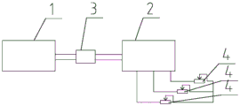
Fig. 4 is a logic block diagram of the preferred embodiment of the present invention.
In the figure 1, a tested permanent magnet synchronous motor 2, a tooling permanent magnet synchronous motor 3, a coupler 4 and a slide rheostat.
Detailed Description
The present invention will now be described in further detail with reference to the accompanying drawings. These drawings are simplified schematic drawings and illustrate the basic structure of the present invention only in a schematic manner, and thus show only the components related to the present invention.
Fig. 1 to 4 show a permanent magnet synchronous motor load test tool, which is used for testing a tested permanent magnet synchronous motor 1.
The test tool comprises a tool permanent magnet synchronous motor 2, the tested permanent magnet synchronous motor 1 is communicated with a power supply through a power line, the output end of the tested permanent magnet synchronous motor 1 is connected with the tool permanent magnet synchronous motor 2 through a coupler 3, and the tool permanent magnet synchronous motor 2 is driven to rotate when the tested permanent magnet synchronous motor 1 is electrified and rotated.
The tool permanent magnet synchronous motor 2 is provided with three-phase windings which are respectively a U-phase winding, a V-phase winding and a W-phase winding. The U-phase winding, the V-phase winding and the W-phase winding are respectively connected with a slide rheostat 4. The tool permanent magnet synchronous motor 2 and the tested permanent magnet synchronous motor 1 can be arranged on the table body, and the slide rheostat 4 is correspondingly connected below the table body.
The load test tool for the permanent magnet synchronous motor has the following test method: when the power supply is electrified, the tested permanent magnet synchronous motor 1 runs, the tested permanent magnet synchronous motor 1 is used as a generator to drive the tool permanent magnet synchronous motor 2 to run, when the rotation speed of the tested permanent magnet synchronous motor 1 is fixed, the rotation speed of the tool permanent magnet synchronous motor 2 is fixed, the mechanical energy of the tool permanent magnet synchronous motor 2 is converted into the heat energy of the slide rheostat 4,
V=S*K1

the resistance of the sliding rheostat 4 is calculated according to the formula:
wherein: t is the unit of torque required for the test n.m,
k1 is the back electromotive force coefficient of the permanent magnet synchronous motor,
v is the U, V, W phase voltage (unit: V) of the tool permanent magnet synchronous motor,
s is the unit RPM/min of the rotating speed of the permanent magnet synchronous motor to be measured,
r is the sliding varistor resistance (unit omega),
k1 is a fixed parameter of the tool permanent magnet synchronous motor 2, and the resistance value R of the slide rheostat 4 can be obtained through the formula according to the rotating speed and the target torque parameter of the permanent magnet synchronous motor 1 to be tested;
and then adjusting the resistance value of the slide rheostat 4 to R, and when the tested motor runs at a fixed speed, the rotating shaft obtains a target torque T to meet the test conditions of the on-load test so as to carry out the on-load test.
In the process of testing and adjusting the resistance value of the sliding rheostat 4, the power of the tool permanent magnet synchronous motor 2 in the operation process has heat loss and mechanical friction loss, and the heat loss and the mechanical friction loss are ignored.
The permanent magnet synchronous motor on-load test tool designed in the way is ingenious in structural design, the resistance value of the slide rheostat 4 is calculated through the rotating speed and the target torque parameter of the tested motor, the target torque is obtained through changing the resistance value of the slide rheostat 4, the rotating shaft can obtain the target torque T through the combination of the tool permanent magnet synchronous motor 2 and the slide damping rheostat, a dynamometer or a magnetic powder brake is effectively replaced, the cost of on-load test is effectively reduced, the maintenance is convenient, and the occupied space is small.
In light of the foregoing, it will be apparent to those skilled in the art from this disclosure that various changes and modifications can be made without departing from the spirit and scope of the invention. The technical scope of the present invention is not limited to the content of the specification, and must be determined according to the scope of the claims.
Claims (1)
1. The utility model provides a PMSM on-load test fixture for test is surveyed PMSM (1), its characterized in that: the test fixture comprises a fixture permanent magnet synchronous motor (2), the tested permanent magnet synchronous motor (1) is communicated with a power supply through a power line, the output end of the tested permanent magnet synchronous motor (1) is connected with the fixture permanent magnet synchronous motor (2) through a coupler (3), the tested permanent magnet synchronous motor (1) is driven to rotate when being electrified and rotated, the fixture permanent magnet synchronous motor (2) is provided with a three-phase winding which is respectively a U-phase winding, a V-phase winding and a W-phase winding, and the U-phase winding, the V-phase winding and the W-phase winding are respectively connected with a sliding rheostat (4).
Priority Applications (1)
| Application Number | Priority Date | Filing Date | Title |
|---|---|---|---|
| CN202023254447.1U CN214310800U (en) | 2020-12-29 | 2020-12-29 | Permanent magnet synchronous motor load test tool |
Applications Claiming Priority (1)
| Application Number | Priority Date | Filing Date | Title |
|---|---|---|---|
| CN202023254447.1U CN214310800U (en) | 2020-12-29 | 2020-12-29 | Permanent magnet synchronous motor load test tool |
Publications (1)
| Publication Number | Publication Date |
|---|---|
| CN214310800U true CN214310800U (en) | 2021-09-28 |
Family
ID=77863632
Family Applications (1)
| Application Number | Title | Priority Date | Filing Date |
|---|---|---|---|
| CN202023254447.1U Active CN214310800U (en) | 2020-12-29 | 2020-12-29 | Permanent magnet synchronous motor load test tool |
Country Status (1)
| Country | Link |
|---|---|
| CN (1) | CN214310800U (en) |
Cited By (1)
| Publication number | Priority date | Publication date | Assignee | Title |
|---|---|---|---|---|
| CN112684339A (en) * | 2020-12-29 | 2021-04-20 | 常州市康迪克至精电机有限公司 | Permanent magnet synchronous motor load test tool and test method |
-
2020
- 2020-12-29 CN CN202023254447.1U patent/CN214310800U/en active Active
Cited By (1)
| Publication number | Priority date | Publication date | Assignee | Title |
|---|---|---|---|---|
| CN112684339A (en) * | 2020-12-29 | 2021-04-20 | 常州市康迪克至精电机有限公司 | Permanent magnet synchronous motor load test tool and test method |
Similar Documents
| Publication | Publication Date | Title |
|---|---|---|
| CN101031719B (en) | Transmission chain for wind power equipment and method for controlling rotation speed or torque | |
| CN101214644B (en) | Frequency conversion electric tool | |
| CN101931353B (en) | Control method for brushless direct current motor for automotive air conditioning fan | |
| Khatab et al. | Comparative study of novel axial flux magnetically geared and conventional axial flux permanent magnet machines | |
| CN107328506A (en) | High-speed electric main shaft dynamometer machine and its application | |
| CN214310800U (en) | Permanent magnet synchronous motor load test tool | |
| CN208479501U (en) | Dual-motor drive circuit | |
| CN102221673B (en) | Test method for copper loss and temperature rise of multi-phase high-power low-speed permanent magnet synchronous motor | |
| CN201263116Y (en) | High-efficiency energy-saving rare-earth permanent magnet direct drive device | |
| CN105703585B (en) | Winding type is brushless coupling transmission device | |
| CN112684339A (en) | Permanent magnet synchronous motor load test tool and test method | |
| CN102004198A (en) | Double-axis feedback low-voltage alternating current variable frequency electric transmission test system and method | |
| CN106300796B (en) | A kind of speed regulating motor | |
| CN204267306U (en) | A kind of high-speed, multi-stage Centrifugal water pump | |
| CN201066816Y (en) | Direct drive permanent magnetic AC brushless digital control electromotor for industrial sewer | |
| CN212343564U (en) | Motor with rotating speed measuring device | |
| CN201669691U (en) | Split type brushless electric tool | |
| CN101106290A (en) | A permanent magnetic synchronization motor | |
| Liu et al. | Experimental evaluation of a radial-radial-flux compound-structure permanent-magnet synchronous machine used for HEVs | |
| CN201204528Y (en) | Low speed large-torque moment motor | |
| CN201140389Y (en) | Frequency conversion electric tool | |
| CN204794626U (en) | Electric tool brushless motor controller ware heat radiation structure | |
| CN211698093U (en) | Servo motor test bench and test system | |
| CN203522473U (en) | AC brushless electric hand drill | |
| CN101881694A (en) | Diesel engine condition simulating test bed |
Legal Events
| Date | Code | Title | Description |
|---|---|---|---|
| GR01 | Patent grant | ||
| GR01 | Patent grant |