CN214308549U - Circle measuring frame for assembling stator of hydraulic generator - Google Patents
Circle measuring frame for assembling stator of hydraulic generator Download PDFInfo
- Publication number
- CN214308549U CN214308549U CN202120625866.7U CN202120625866U CN214308549U CN 214308549 U CN214308549 U CN 214308549U CN 202120625866 U CN202120625866 U CN 202120625866U CN 214308549 U CN214308549 U CN 214308549U
- Authority
- CN
- China
- Prior art keywords
- adjusting
- stand
- position sleeve
- hydraulic generator
- stator
- Prior art date
- Legal status (The legal status is an assumption and is not a legal conclusion. Google has not performed a legal analysis and makes no representation as to the accuracy of the status listed.)
- Active
Links
Images

Landscapes
- Manufacture Of Motors, Generators (AREA)
Abstract
The utility model belongs to the technical field of hydraulic generator stator measuring equipment, specifically be hydraulic generator stator assembly is with surveying circle frame, the on-line screen storage device comprises a base, fixedly connected with stand on the base, it is equipped with the position sleeve to rotate the cover on the stand, fixedly connected with is used for supporting position sleeve pivoted supporting platform on the stand, supporting platform's upper surface is perpendicular with the axis of stand, be provided with adjustment mechanism between position sleeve and the stand, be connected with the measurement support arm on the position sleeve, it is provided with two to measure the support arm and set up along the axis symmetry of position sleeve for two.
Description
Technical Field
The utility model belongs to the technical field of hydraulic generator stator measuring equipment, specifically be hydraulic generator stator assembly is with surveying circle frame.
Background
When a stator of a medium-large hydraulic generator is installed, the concentricity of an inner circle of the stator and a dove tail rib needs to be ensured, and usually, a stator circle measuring frame is adopted for detecting the roundness of the dove tail rib of the stator and the roundness of the inner diameter of the stator after lamination. The existing circle measuring frame structure comprises a stand column, a base, a positioning sleeve, a measuring support arm, a counterweight and other parts, wherein the positioning sleeve is sleeved on the stand column, the horizontal support arm is connected and fixed on the positioning sleeve, the counterweight is arranged on one side, opposite to the horizontal support arm, of the positioning sleeve, an adjusting screw for adjusting the gap width between the positioning sleeve and the stand column is arranged on the positioning sleeve, the positioning sleeve and the stand column can be in a coaxial state through the adjusting screw, a dial indicator is installed on the measuring support arm, and the roundness of a stator of a generator can be measured by rotating the measuring support arm around the stand column. In actual use, because the gravity center of the balance weight part and the distance from the gravity center of the horizontal supporting arm to the axis of the upright post are different, the abrasion of the adjusting screw is different, and the roundness measured by the circle measuring frame is inaccurate.
SUMMERY OF THE UTILITY MODEL
An object of the utility model is to provide a hydraulic generator stator assembly is with surveying circle frame to survey the circle frame and lead to measuring unsafe problem because of wearing and tearing easily among the solution prior art.
In order to achieve the aim, the utility model discloses a basic scheme provides a hydraulic generator stator assembly is with surveying circle frame, the on-line screen storage device comprises a base, fixedly connected with stand on the base, it is equipped with the position sleeve to rotate the cover on the stand, fixedly connected with is used for supporting position sleeve pivoted supporting platform on the stand, supporting platform's upper surface is perpendicular with the axis of stand, be provided with adjustment mechanism between position sleeve and the stand, be connected with the measurement support arm on the position sleeve, it is provided with two to measure the support arm and set up along the axis symmetry of position sleeve for two.
The principle and the beneficial effect of the basic scheme are as follows: through the symmetry set up two and measure the support arm on the position sleeve to make the focus of position sleeve both sides unanimous, thereby make between position sleeve and the stand can not appear leading to the inconsistent problem of adjustment mechanism wearing and tearing between position sleeve and the stand because of the focus is inconsistent, thereby make the measurement more accurate. Simultaneously, set up two and measure the support arm, carry out the measurement of circularity simultaneously through two measurement support arms to conveniently utilize two to measure the support arm measuring result and verify each other, in time discover the great condition of error, thereby be favorable to improving and measure the accuracy.
Further, adjustment mechanism is including adjusting the seat, the direction sliding connection who adjusts the seat and go up towards the stand has the dabber, be connected with the screw thread regulating part along the slip direction of dabber between dabber and the regulation seat, the dabber is connected with the horizontal support bearing towards the one end of stand, the axis of horizontal support bearing and the axis coplane of stand, it can dismantle with the position sleeve and be connected to adjust the seat.
By adopting the arrangement, the mandrel is abutted against the upright post through the transverse supporting bearing, so that the abrasion between the mandrel and the upright post can be reduced; the threaded adjusting piece drives the mandrel to slide relative to the adjusting seat, so that the distance between the adjusting seat and the stand column is adjusted, the size of a gap between the positioning sleeve and the stand column is adjusted through movement of the adjusting seat, coaxial arrangement of the positioning sleeve and the stand column is achieved, and assembly operation between the positioning sleeve and the stand column is facilitated.
Further, the thread adjusting piece comprises a first thread adjusting piece and a second thread adjusting piece, the first thread adjusting piece comprises a first adjusting rod, one end of the first adjusting rod is statically connected with the adjusting seat, a through hole for the first adjusting rod to pass through is formed in the mandrel, and the first adjusting rod is in threaded connection with a first adjusting nut; the second thread adjusting piece comprises a second adjusting rod, the second adjusting rod is in threaded connection with the mandrel, and one end of the second adjusting rod is in contact with the adjusting seat.
By adopting the arrangement, the first adjusting nut can be rotated to push the mandrel to slide towards the direction of the upright post under the tensile force of the first adjusting rod; by rotating the second adjusting rod, the second adjusting rod can push the mandrel to slide towards the direction far away from the upright post under the supporting action of the adjusting seat. Therefore, the relative position between the mandrel and the adjusting seat can be adjusted in a sliding mode through the matching of the first thread adjusting piece and the second thread adjusting piece, and therefore the gap between the positioning sleeve and the stand column can be conveniently adjusted.
Further, the sliding joint surface between the mandrel and the adjusting seat is a cylindrical joint surface. By adopting the arrangement, the processing of the joint surface between the mandrel and the adjusting seat is easier, thereby reducing the processing and manufacturing difficulty and further reducing the cost.
Furthermore, the transverse support bearing is connected with the core shaft through a pin shaft, the core shaft is provided with a pin hole matched with the pin shaft in a penetrating mode along the radial direction, and the outer diameter of the transverse support bearing is smaller than the length of the pin hole. By adopting the arrangement, the transverse supporting bearing is conveniently assembled on the mandrel.
Furthermore, the positioning sleeve is connected with a universal wheel which is matched with the supporting platform in a rolling way. By adopting the arrangement, the positioning sleeve can rotate smoothly under the supporting action of the supporting platform.
Furthermore, the upper end and the lower end of the locating sleeve are respectively provided with four adjusting mechanisms which are distributed in an annular array around the axis of the locating sleeve. By adopting the arrangement, the width of the gap between the upper end and the lower end of the positioning sleeve and the upright post can be adjusted by the adjusting mechanism, and meanwhile, the adjusting mechanism is distributed in an annular array, so that the operation is more convenient when the gap is adjusted.
Drawings
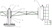
Fig. 1 is a schematic view of an embodiment of a circle measuring frame for assembling a stator of a hydraulic generator according to the present invention;
FIG. 2 is a schematic distribution diagram of the adjusting mechanism and the universal wheels at the lower end of the positioning sleeve in FIG. 1;
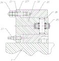
FIG. 3 is a schematic view of the adjustment mechanism of FIG. 1;
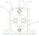
fig. 4 is a left side view of the adjustment mechanism of fig. 3.
Detailed Description
The following is further detailed by way of specific embodiments:
reference numerals in the drawings of the specification include: the device comprises a generator stator A, a stand column 1, an adjusting mechanism 2, a locating sleeve 3, a measuring supporting arm 4, a universal wheel 5, a supporting platform 6, a base 7, an adjusting seat 21, a mandrel 22, a protruding part 221, a first adjusting rod 23, a first adjusting nut 24, a transverse supporting bearing 25, a pin shaft 26 and a second adjusting rod 27.
The embodiment is basically as shown in the attached figures 1 and 2: circle of surveying frame is used in hydraulic generator stator assembly, including base 7, welded fastening has columniform stand 1 on the base 7, and 1 middle part welded fastening of stand has annular supporting platform 6, and supporting platform 6's upper surface is perpendicular with stand 1's axis. And a positioning sleeve 3 sleeved on the upright post 1 is arranged above the supporting platform 6, and the positioning sleeve 3 is in running fit with the upright post 1. The lower extreme of position sleeve 3 has four universal wheels 5 through bolted connection, and four universal wheels 5 are the annular array distribution around the axis of position sleeve 3, and position sleeve 3 passes through universal wheel 5 and supporting platform 6 contact. The upper end and the lower end of the locating sleeve 3 are respectively connected with four adjusting mechanisms 2 through bolts, and the adjusting mechanisms 2 are distributed in an annular array around the axis of the locating sleeve 3. The locating sleeve 3 is connected with two transverse measuring supporting arms 4 through bolts, and the two measuring supporting arms 4 are symmetrically arranged along the axis of the locating sleeve 3.
As shown in fig. 3 and 4, the adjusting mechanism 2 includes an adjusting seat 21, the adjusting seat 21 is connected with the positioning sleeve 3 through a bolt, a core shaft 22 is connected to the adjusting seat 21 in a sliding manner along the radial direction of the positioning sleeve 3, the core shaft 22 penetrates through the adjusting seat 21, and a sliding joint surface between the core shaft 22 and the adjusting seat 21 is a cylindrical joint surface; a thread adjusting part is arranged between one end of the mandrel 22, which is far away from the axis of the positioning sleeve 3, and the adjusting seat 21, and comprises a first thread adjusting part and a second thread adjusting part, in the embodiment, a protruding part 221 which extends along the radial direction of the mandrel 22 is integrally formed at one end of the mandrel 22, which is far away from the axis of the positioning sleeve 3, and a through hole and a threaded hole which are parallel to the sliding direction of the mandrel 22 are arranged on the protruding part 221; the first thread adjusting piece comprises a first adjusting rod 23, one end of the first adjusting rod 23 penetrates through the through hole and then is in threaded connection with the adjusting seat 21, and a first adjusting nut 24 is in threaded connection with one side, away from the adjusting seat 21, of the protruding portion 221 on the first adjusting rod 23; the second threaded adjusting piece comprises a second adjusting rod 27, the second adjusting rod 27 is in threaded connection with the threaded hole on the boss 221, and one end of the second adjusting rod 27 is in contact with the adjusting seat 21; a transverse support bearing 25 is arranged at one end of the mandrel 22 close to the axis of the positioning sleeve 3, a pin hole is arranged on the mandrel 22 in a penetrating manner along the radial direction, a pin shaft 26 connected with an inner ring of the transverse support bearing 25 is arranged in the pin hole, the outer diameter of the transverse support shaft is smaller than the length of the pin hole, and in the embodiment, the transverse support bearing 25 is preferably a ball bearing.
The specific implementation process is as follows: after the levelness and the roundness of the base of the generator are corrected, the upright post 1 of the circle measuring frame is installed on the base through the base 7, and the verticality of the upright post 1 is corrected, so that the coaxiality of the upright post 1 and the base is smaller than or equal to 1 mm. The position sleeve 3 that will install adjustment mechanism 2 and universal wheel 5 assembles on stand 1 to adjust the gap between back position sleeve 3 and the stand 1 through adjustment mechanism 2, thereby make position sleeve 3 and stand 1 be in coaxial state, specific theory of operation is: when the first thread adjusting piece is in an unstressed state, the second adjusting rod 27 of the second thread adjusting piece is rotated to drive the mandrel 22 to slide towards the axis direction far away from the positioning sleeve 3, so that the width of a gap between the position of the positioning sleeve 3 where the corresponding adjusting mechanism 2 is arranged and the upright post 1 is reduced; on the contrary, when the second threaded adjusting member is in an unstressed state, the first adjusting nut 24 is rotated, so that the first adjusting nut 24 pushes the core shaft 22 to move towards the axial direction of the positioning sleeve 3, thereby increasing the width of the gap between the position of the positioning sleeve 3 where the corresponding adjusting mechanism 2 is arranged and the upright post 1. And finally, the two measuring support arms 4 are symmetrically assembled on the positioning sleeve 3, and the measuring operation of the generator stator A can be started by installing the dial indicator on the measuring support arms 4.
The above description is only an example of the present invention, and the common general knowledge of the known specific structures and characteristics of the embodiments is not described herein. It should be noted that, for those skilled in the art, without departing from the structure of the present invention, several modifications and improvements can be made, which should also be regarded as the protection scope of the present invention, and these will not affect the effect of the implementation of the present invention and the practicability of the patent.
Claims (7)
1. Circle frame is surveyed with assembly of hydraulic generator stator, the on-line screen storage device comprises a base, fixedly connected with stand on the base, it is equipped with the position sleeve to rotate the cover on the stand, fixedly connected with is used for supporting position sleeve pivoted supporting platform on the stand, supporting platform's upper surface is perpendicular with the axis of stand, be provided with adjustment mechanism between position sleeve and the stand, be connected with on the position sleeve and measure support arm, its characterized in that: the measuring support arms are arranged in two numbers, and the two measuring support arms are symmetrically arranged along the axis of the positioning sleeve.
2. The circle measuring frame for assembling the stator of the hydraulic generator according to claim 1, characterized in that: adjustment mechanism is including adjusting the seat, the direction sliding connection who moves towards the stand on adjusting the seat has the dabber, the dabber is connected with the screw thread regulating part with adjusting along the slip direction of dabber between the seat, the dabber is connected with horizontal support bearing towards the one end of stand, the axis of horizontal support bearing and the axis coplane of stand, it can dismantle with the position sleeve and be connected to adjust the seat.
3. The circle measuring frame for assembling the stator of the hydraulic generator according to claim 2, characterized in that: the thread adjusting piece comprises a first thread adjusting piece and a second thread adjusting piece, the first thread adjusting piece comprises a first adjusting rod, one end of the first adjusting rod is statically connected with the adjusting seat, a through hole for the first adjusting rod to pass through is formed in the mandrel, and the first adjusting rod is in threaded connection with a first adjusting nut; the second thread adjusting piece comprises a second adjusting rod, the second adjusting rod is in threaded connection with the mandrel, and one end of the second adjusting rod is in contact with the adjusting seat.
4. The circle measuring frame for assembling the stator of the hydraulic generator according to claim 3, wherein: the sliding joint surface between the mandrel and the adjusting seat is a cylindrical joint surface.
5. The circle measuring frame for assembling the stator of the hydraulic generator according to claim 4, wherein: the transverse supporting bearing is connected with the core shaft through a pin shaft, a pin hole matched with the pin shaft is arranged on the core shaft in a penetrating mode along the radial direction, and the outer diameter of the transverse supporting bearing is smaller than the length of the pin hole.
6. The circle measuring frame for assembling the stator of the hydraulic generator according to claim 5, wherein: and the positioning sleeve is connected with a universal wheel which is matched with the supporting platform in a rolling way.
7. The circle measuring frame for assembling the stator of the hydraulic generator according to claim 6, wherein: the upper end and the lower extreme of position sleeve are provided with four adjustment mechanism respectively, adjustment mechanism is the annular array around the axis of position sleeve and distributes.
Priority Applications (1)
| Application Number | Priority Date | Filing Date | Title |
|---|---|---|---|
| CN202120625866.7U CN214308549U (en) | 2021-03-29 | 2021-03-29 | Circle measuring frame for assembling stator of hydraulic generator |
Applications Claiming Priority (1)
| Application Number | Priority Date | Filing Date | Title |
|---|---|---|---|
| CN202120625866.7U CN214308549U (en) | 2021-03-29 | 2021-03-29 | Circle measuring frame for assembling stator of hydraulic generator |
Publications (1)
| Publication Number | Publication Date |
|---|---|
| CN214308549U true CN214308549U (en) | 2021-09-28 |
Family
ID=77837444
Family Applications (1)
| Application Number | Title | Priority Date | Filing Date |
|---|---|---|---|
| CN202120625866.7U Active CN214308549U (en) | 2021-03-29 | 2021-03-29 | Circle measuring frame for assembling stator of hydraulic generator |
Country Status (1)
| Country | Link |
|---|---|
| CN (1) | CN214308549U (en) |
-
2021
- 2021-03-29 CN CN202120625866.7U patent/CN214308549U/en active Active
Similar Documents
| Publication | Publication Date | Title |
|---|---|---|
| CN107907331B (en) | Wheel hub bearing rigidity testing machine | |
| CN214308549U (en) | Circle measuring frame for assembling stator of hydraulic generator | |
| CN113640939B (en) | Two-dimensional angle precise adjustment device for large-caliber plane mirror | |
| CN2082396U (en) | Internal diameter testing instrument | |
| CN202770377U (en) | Roundness measuring frame for rotors of large hydrogenerator | |
| CN101750002B (en) | Coaxial rotating position error detector | |
| CN219141719U (en) | Roundness detector for outer raceway of tapered roller bearing inner ring | |
| CN208313232U (en) | A kind of Deformation inspection equipment | |
| CN205138394U (en) | Circle frame is surveyed to simple and easy rotor | |
| CN217453219U (en) | Main shaft rotation error measuring device | |
| CN214702578U (en) | Horizontal magnetic loading rolling bearing friction torque measurement testing machine | |
| CN214308550U (en) | Circle measuring frame for hydraulic generator rotor | |
| CN113237405A (en) | Rotor circle measuring frame and using method thereof | |
| CN213336062U (en) | Precision cold-rolled seamless steel tube straightness detection device | |
| CN202384941U (en) | Roundness measuring support for stator assembly of hydrogenerator | |
| CN212931902U (en) | Contact angle detector for angular contact ball bearing | |
| CN201207601Y (en) | Measurement device for rotor assembly of vertical type hydro-turbo generator set | |
| CN212030863U (en) | Sensor mounting bracket | |
| CN207621602U (en) | A kind of universal suspension gear of Laser Line Marker | |
| CN106908235B (en) | A kind of experimental provision measuring micro- spray lubricating arrangement lubrication micro- amount of redundancy of oil spurts | |
| CN211317189U (en) | Coaxiality measuring instrument | |
| CN220380508U (en) | Wall post structure straightness detection device that hangs down | |
| CN217424209U (en) | Differential mechanism half shell structure inner spherical surface measuring device | |
| CN219347721U (en) | Wind-powered electricity generation wheel hub flange port is with examining utensil | |
| CN214407239U (en) | Rotor circle measuring frame |
Legal Events
| Date | Code | Title | Description |
|---|---|---|---|
| GR01 | Patent grant | ||
| GR01 | Patent grant |