CN214227930U - Connecting circuit for improving reliability of industrial UPS power supply - Google Patents
Connecting circuit for improving reliability of industrial UPS power supply Download PDFInfo
- Publication number
- CN214227930U CN214227930U CN202022613237.0U CN202022613237U CN214227930U CN 214227930 U CN214227930 U CN 214227930U CN 202022613237 U CN202022613237 U CN 202022613237U CN 214227930 U CN214227930 U CN 214227930U
- Authority
- CN
- China
- Prior art keywords
- switch
- ups
- power supply
- static transfer
- static
- Prior art date
- Legal status (The legal status is an assumption and is not a legal conclusion. Google has not performed a legal analysis and makes no representation as to the accuracy of the status listed.)
- Active
Links
Images


Abstract
The utility model provides an improve connecting circuit of industrial UPS power reliability, includes bypass power cabinet, first UPS power and second UPS power, power load cabinet, and the input of first bus and second bus is connected first static change over switch and second static change over switch respectively, and first static change over switch and second static change over switch interconnect are connected. The two sets of UPS power supply parallel operation modes adopt a sectional operation mode, the bus is divided into a first bus and a second bus, the buses are in an electrical isolation state, one path of fault cannot cause damage of components on the other path, the two sets of UPS power supplies are mutually standby power supplies, and a bypass power supply is added, so that the reliability of the system is greatly improved.
Description
Technical Field
The utility model relates to a UPS power supply field, especially a improve connecting circuit of industry UPS power reliability.
Background
The UPS has the advantages of continuous, stable and uninterrupted power supply, and the UPS parallel system has the advantages of N + X redundancy, expandability, easy maintenance and the like, so the UPS is widely applied to power supply and power failure protection of industrial important loads.
The bus-bar is integrated in the two sets of UPS parallel operation modes of the current main stream, when faults such as short circuit generated by the bus-bar or any load connected with the bus-bar lead to current increase, all loads on the bus face the risk of damage caused by current increase, partial enterprises adopt the mode of directly changing the output of the two sets of UPS into the sectional operation mode, and the reliability of power supply is reduced. Or four sets of UPS are adopted, and each two sets of UPS are operated in parallel to form two sections of buses, so that the purpose of sectional operation is achieved.
The core elements with power and heating, such as a large electrolytic capacitor, a rectifier, an inverter and the like in the UPS host machine, can age gradually along with the running time, the inherent service life of the UPS is generally 10 years, and the UPS needs to be integrally modified, and due to the importance of UPS load equipment, in order to ensure that the load still can not be powered off and normally works during the integral fault maintenance or modification of the UPS host machine, a large number of temporary cables must be laid to temporarily supply power to each load at present, and the running risk of the load is higher during the period.
Disclosure of Invention
The utility model aims to solve the technical problem that a connection circuit that improves industry UPS power reliability is provided, can be when female section operation of arranging, guarantee the reliability of power supply, and can carry out the troubleshooting or guarantee not make the load normal work that falls the electricity when changing the period in UPS corresponding part and examine and repair.
In order to solve the technical problem, the utility model discloses the technical scheme who adopts is:
the utility model provides an improve connecting circuit of industrial UPS power reliability, including bypass power cabinet, first UPS power and second UPS power, the power load cabinet, be equipped with first generating line and second generating line in the power load cabinet, first generating line and second generating line output are connected with the load, first static transfer switch and the static change over switch of second are connected respectively to the input of first generating line and second generating line, first static change over switch and the static change over switch interconnect of second are connected, first UPS power and second UPS power output are connected respectively to the first switch input of first static change over switch and the static change over switch of second, the bypass input of first UPS power and second UPS power is connected with bypass power cabinet output.
The interconnection structure of the first static transfer switch and the second static transfer switch comprises: the first switch and the second switch output end of the first static transfer switch are connected in parallel, the first switch and the second switch output end of the second static transfer switch are connected in parallel, the second switch input end of the first static transfer switch is electrically connected with the first switch input end of the second static transfer switch, and the first switch input end of the first static transfer switch is electrically connected with the second switch input end of the second static transfer switch.
In an optimized scheme, the output end of the bypass power supply cabinet is provided with power supply breakers QF2, QF3, QF4 and QF5, the output end of QF2 is connected with the bypass input end of the first UPS power supply, the output end of QF5 is connected with the bypass input end of the second UPS power supply, the output end of QF3 is electrically connected with the input end of the first bus, and the output end of QF4 is electrically connected with the input end of the second bus.
An outlet switch QF6 is arranged between the first busbar and the first static change-over switch, and an outlet switch QF7 is arranged between the second busbar and the second static change-over switch.
The output end of the power supply breaker QF3 is electrically connected with the output end of the outlet switch QF6, and the output end of the power supply breaker QF4 is electrically connected with the output end of the outlet switch QF 7.
In an optimized scheme, a breaker QF8 is arranged between the first UPS power supply and the first static transfer switch, and a breaker QF9 is arranged between the second UPS power supply and the second static transfer switch.
Static transfer switches are arranged in the first UPS power supply and the second UPS power supply, one switch in the static transfer switches is connected with the UPS power supply, and the other switch in the static transfer switches is connected with the bypass power supply cabinet.
The utility model provides a pair of improve connecting circuit of industry UPS power reliability, two sets of UPS power parallel operation modes adopt the segmentation operation mode, divide into first generating line and second generating line with the generating line, be in electrical isolation state between the generating line, wherein the trouble of the same kind can not arouse that another way's components and parts damage, and each other is stand-by power supply between two sets of UPS power, the bypass power supply that adds again, make the reliability of system promote greatly, it is through setting up the power supply short circuit at the bypass power supply simultaneously, set up inlet wire switch at the generating line inlet end, and set up the circuit breaker between UPS power and the static transfer switch, can be at the UPS power of arbitrary all the way, when static transfer switch or bypass power overhauld, realize not stopping the power and overhaul.
Drawings
The invention will be further explained with reference to the following figures and examples:
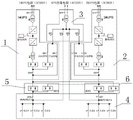
FIG. 1 is a schematic diagram of the overall circuit connection of the present invention;
FIG. 2 is a schematic diagram of a partial connection of a static transfer switch and a power load cabinet;
FIG. 3 is a schematic diagram of a UPS power supply;
fig. 4 is a schematic circuit connection diagram of the preferred embodiment.
In the figure: the UPS comprises a bypass power cabinet 1, a first UPS power supply 2, a second UPS power supply 3, a power load cabinet 4, a first static transfer switch 5, a second static transfer switch 6, a first bus 7 and a second bus 8.
Detailed Description
As shown in fig. 1-3, a connection circuit for improving reliability of an industrial UPS power supply comprises a bypass power supply cabinet 1, a first UPS power supply 2 and a second UPS power supply 3, and a power load cabinet 4, wherein a first bus 7 and a second bus 8 are arranged in the power load cabinet 4, outputs of the first bus 7 and the second bus 8 are connected with a load, inputs of the first bus 7 and the second bus 8 are respectively connected with a first static transfer switch 5 and a second static transfer switch 6, the first static transfer switch 5 and the second static transfer switch 6 are connected with each other, first switch inputs of the first static transfer switch 5 and the second static transfer switch 6 are respectively connected with outputs of the first UPS power supply 2 and the second UPS power supply 3, bypass inputs of the first UPS power supply 2 and the second UPS power supply 3 are connected with an output of the bypass power supply cabinet 1, and the first static transfer switch 5 and the second static transfer switch 6 are interconnected, the first UPS power source 2 and the second UPS power source 3 are mutually in bypass standby power relationship, when the first static transfer switch 5 and the second static transfer switch 6 detect that the power of the first switch inside is lost, the second switch is automatically started, and the bypass connected with the second switch provides power for the bus.
As shown in fig. 1 and 2, the interconnection structure of the first static transfer switch 5 and the second static transfer switch 6 is as follows: the first switch and the second switch output end of the first static transfer switch 5 are connected in parallel, the first switch and the second switch output end of the second static transfer switch 6 are connected in parallel, the second switch input end of the first static transfer switch 5 is electrically connected with the first switch input end of the second static transfer switch 6, the first switch input end of the first static transfer switch 5 is electrically connected with the second switch input end of the second static transfer switch 6, the first switch and the second switch of one are mutually bypass power supplies through the connection of the first static transfer switch 5 and the second static transfer switch 6, and the main power supply or the bypass power supply can be automatically switched and selected through the static transfer switches according to the current power state of the first switch.
The optimized scheme is as shown in fig. 1, the output end of the bypass power cabinet 1 is provided with power supply breakers QF2, QF3, QF4 and QF5, the output end of QF2 is connected with the bypass input end of the first UPS power supply 2, the output end of QF5 is connected with the bypass input end of the second UPS power supply 3, the output end of QF3 is electrically connected with the input end of the first bus 7, the output end of QF4 is electrically connected with the input end of the second bus 8, and by providing the power supply breakers QF2 and QF5, when the UPS power supply fails or is overhauled, all power connections of the UPS are disconnected by disconnecting the inlet line power supply of the UPS and the QF2 or QF5, so that the UPS can perform neutral overhaul, and simultaneously, when the two UPS power supplies are simultaneously powered off or the static transfer switch fails, the bypass power supply is supplied to the bypass bus.
As shown in fig. 1 and 2, an outlet switch QF6 is provided between the first busbar 7 and the first static transfer switch 5, and an outlet switch QF7 is provided between the second busbar 8 and the second static transfer switch 6.
As shown in fig. 1, the output end of the power supply breaker QF3 is electrically connected to the output end of the outgoing switch QF6, the output end of the power supply breaker QF4 is electrically connected to the output end of the outgoing switch QF7, and by providing the outgoing switches QF6 and QF7, the connection between the bus and the UPS power supply can be disconnected, so that the UPS power supply and the static transfer switch can be conveniently dismounted and overhauled.
The optimized scheme is as shown in fig. 4, a breaker QF8 is arranged between the first UPS power supply 2 and the first static transfer switch 5, a breaker QF9 is arranged between the second UPS power supply 3 and the second static transfer switch 6, the breakers QF8, QF2 and Q1 are disconnected at the same time, both the incoming line power supply and the bypass power supply of the first UPS power supply 2 are lost, the first UPS power supply 2 can be independently removed for maintenance or replacement, and similarly, the second UPS power supply 3 can be independently removed for maintenance or replacement;
when the QF8 and the QF6 are disconnected simultaneously and the QF3 is switched on, the first bus 7 is powered by the bypass power cabinet 1, the first static transfer switch 5 is disconnected from the first UPS power supply 2 and the first bus 7, the first static transfer switch 5 can be detached alone for maintenance or replacement, and similarly, the second static transfer switch 6 can also be detached alone for maintenance or replacement.
Static transfer switches are arranged in the first UPS power supply 2 and the second UPS power supply 3, one switch in the static transfer switch is connected with the UPS power supply, the other switch in the static transfer switch is connected with the bypass power supply cabinet 1, and the static transfer switches in the first UPS power supply 2 and the second UPS power supply 3 can automatically select whether the incoming line power supply or the bypass power supply cabinet 1 supplies power according to the condition of the UPS incoming line power supply.
Claims (7)
1. The utility model provides an improve connecting circuit of industry UPS power reliability, includes bypass power cabinet (1), first UPS power (2) and second UPS power (3), power load cabinet (4), characterized by: be equipped with first busbar (7) and second busbar (8) in power load cabinet (4), first busbar (7) and second busbar (8) output are connected with the load, first static change over switch (5) and second static change over switch (6) are connected respectively to the input of first busbar (7) and second busbar (8), first static change over switch (5) and second static change over switch (6) interconnect connection, the first switch input of first static change over switch (5) and second static change over switch (6) is connected first UPS power (2) and second UPS power (3) output respectively, the bypass input of first UPS power (2) and second UPS power (3) is connected with bypass power cabinet (1) output.
2. A connection circuit for improving reliability of an industrial UPS power supply according to claim 1, wherein the first static transfer switch (5) and the second static transfer switch (6) are interconnected in the following structure: the first switch and the second switch output end of the first static transfer switch (5) are connected in parallel, the first switch and the second switch output end of the second static transfer switch (6) are connected in parallel, the second switch input end of the first static transfer switch (5) is electrically connected with the first switch input end of the second static transfer switch (6), and the first switch input end of the first static transfer switch (5) is electrically connected with the second switch input end of the second static transfer switch (6).
3. The connection circuit for improving the reliability of the industrial UPS according to claim 2, wherein the output end of the bypass power supply cabinet (1) is provided with power supply breakers QF2, QF3, QF4 and QF5, the output end of QF2 is connected with the bypass input end of the first UPS (2), the output end of QF5 is connected with the bypass input end of the second UPS (3), the output end of QF3 is electrically connected with the input end of the first busbar (7), and the output end of QF4 is electrically connected with the input end of the second busbar (8).
4. The connection circuit for improving the reliability of the industrial UPS according to claim 3, wherein: an outlet switch QF6 is arranged between the first bus (7) and the first static transfer switch (5), and an outlet switch QF7 is arranged between the second bus (8) and the second static transfer switch (6).
5. The connection circuit for improving the reliability of the industrial UPS according to claim 4, wherein: the output end of the power supply breaker QF3 is electrically connected with the output end of the outlet switch QF6, and the output end of the power supply breaker QF4 is electrically connected with the output end of the outlet switch QF 7.
6. The connection circuit for improving the reliability of the industrial UPS according to claim 5, wherein: a circuit breaker QF8 is arranged between the first UPS power source (2) and the first static transfer switch (5), and a circuit breaker QF9 is arranged between the second UPS power source (3) and the second static transfer switch (6).
7. The connection circuit for improving the reliability of the industrial UPS according to claim 1, wherein: and static transfer switches are arranged in the first UPS power supply (2) and the second UPS power supply (3), one switch in the static transfer switches is connected with the UPS power supply, and the other switch is connected with the bypass power supply cabinet (1).
Priority Applications (1)
| Application Number | Priority Date | Filing Date | Title |
|---|---|---|---|
| CN202022613237.0U CN214227930U (en) | 2020-11-12 | 2020-11-12 | Connecting circuit for improving reliability of industrial UPS power supply |
Applications Claiming Priority (1)
| Application Number | Priority Date | Filing Date | Title |
|---|---|---|---|
| CN202022613237.0U CN214227930U (en) | 2020-11-12 | 2020-11-12 | Connecting circuit for improving reliability of industrial UPS power supply |
Publications (1)
| Publication Number | Publication Date |
|---|---|
| CN214227930U true CN214227930U (en) | 2021-09-17 |
Family
ID=77697213
Family Applications (1)
| Application Number | Title | Priority Date | Filing Date |
|---|---|---|---|
| CN202022613237.0U Active CN214227930U (en) | 2020-11-12 | 2020-11-12 | Connecting circuit for improving reliability of industrial UPS power supply |
Country Status (1)
| Country | Link |
|---|---|
| CN (1) | CN214227930U (en) |
-
2020
- 2020-11-12 CN CN202022613237.0U patent/CN214227930U/en active Active
Similar Documents
| Publication | Publication Date | Title |
|---|---|---|
| US7061139B2 (en) | System for providing assured power to a critical load | |
| CN208028652U (en) | A kind of double host parallel redundancy power supply systems | |
| CN108199422A (en) | A kind of operational mode switching system based on both ends flexible direct current power distribution network | |
| CN110943525A (en) | DC power supply system with optimal topology and intrinsic safety | |
| WO2023000585A1 (en) | Low-voltage transformer area load non-power-cut switching system and working method thereof | |
| CN213521301U (en) | Data center power distribution system | |
| CN109687569A (en) | Data center's power supply system | |
| CN214227930U (en) | Connecting circuit for improving reliability of industrial UPS power supply | |
| CN110690755A (en) | Communication power supply system | |
| CN201075725Y (en) | Series connection double bus electricity supply system standby with each other | |
| CN102244395A (en) | Power distribution circuit of UPS (uninterruptible power supply) | |
| CN110556794B (en) | Bus bar protection configuration method of multi-end hybrid direct current system | |
| CN111342549A (en) | Power supply system is synthesized to inside of large-scale coal-electricity integration power station | |
| CN111614151A (en) | Method and structure for live-line-free maintenance of UPS (uninterrupted Power supply) host system | |
| CN219999093U (en) | Main and standby power supply automatic conversion control device for dust removal system and dust removal system | |
| CN110932254A (en) | Multiple redundant power supply control system and method | |
| CN211606101U (en) | Power supply fast switching device system | |
| CN210806838U (en) | Communication power supply system | |
| CN218472832U (en) | Power supply system | |
| CN217427761U (en) | Automatic access system of standby charger | |
| CN219499026U (en) | Multi-loop UPS system with short-circuit protection | |
| CN116031924B (en) | Current transformer station power system wiring and operation method with security section | |
| CN220857704U (en) | Interconnection type direct current power supply circuit | |
| CN114362182B (en) | Four-terminal flexible direct-current interconnection dicyclo network distribution system | |
| CN116488321B (en) | Power distribution system and data center power system |
Legal Events
| Date | Code | Title | Description |
|---|---|---|---|
| GR01 | Patent grant | ||
| GR01 | Patent grant |