Gate for hydraulic engineering
Technical Field
The utility model relates to a hydraulic engineering equipment technical field specifically is gate for hydraulic engineering.
Background
Water conservancy refers to the development of hydraulic resources or the prevention of flood disasters, also called hydraulic engineering, which is an engineering constructed for controlling and allocating surface water and underground water in the nature to achieve the purposes of removing harm and benefiting benefits, and needs to construct various types of hydraulic buildings such as dams, dikes, spillways, sluice gates, water inlets, channels, ferry tanks, rafts, fishways and the like to achieve the aims of the engineering.
After the gate is closed, water flow has continuous pressure to the gate, and the bottom of the gate is usually not provided with a clamping groove for preventing silt from gathering, so that the pressure resistance of the bottom of the gate to the water flow is weaker, the deformation of the gate is easily caused in long-term use, and the gate cannot be durable.
For this reason, a gate for hydraulic engineering is proposed to solve the above problems.
SUMMERY OF THE UTILITY MODEL
An object of the utility model is to provide a gate for hydraulic engineering to solve the problem that proposes in the above-mentioned background art.
In order to achieve the above object, the utility model provides a following technical scheme: the gate for the hydraulic engineering comprises a gate plate, a support frame and a motor, wherein the top end of the support frame is fixedly connected with a fixed seat, the top end of the fixed seat is fixedly connected with the motor, the output shaft of the motor is fixedly connected with one end of a rotating shaft, the other end of the rotating shaft is rotatably connected with an inserted fixed block, the bottom end of the fixed block is fixedly connected with the top end of the support frame, one end of a steel cable is fixedly connected with the periphery of the rotating shaft, the steel cable passes through the inner side of a through hole, the through hole is arranged at the top of the support frame in a penetrating way, the other end of the steel cable is fixedly connected with the top end of a fixed lug, the bottom end of the fixed lug is fixedly connected with the top end of the gate plate, slide grooves are slidably connected with the periphery of the slide blocks and are arranged at the inner side of the support frame, a reinforcing plate is fixedly connected with the bottom of the rear side of the gate plate, a limiting frame is arranged at the side of the reinforcing plate and is connected with a support mechanism, the supporting mechanism comprises a fixed column, the fixed column is close to one side of the back of the flashboard and is hinged to connect a hydraulic telescopic rod and one end of a sleeve, the other end of the hydraulic telescopic rod is hinged to connect the upper surface of the sleeve far away from one side of the fixed column, the fixed end of the hydraulic telescopic rod is connected with a hydraulic cylinder through an oil pipe, the hydraulic cylinder is fixedly installed on the front side of the fixed column, a hollow inner cavity is formed in the sleeve, one end of a spring is fixedly connected to the bottom wall of the hollow inner cavity and is fixed to the inner side of a movable block, the inner side wall of the hollow inner cavity is slidably connected to the periphery of the movable block, one end of a movable rod is fixedly connected to the outer side of the movable rod, the other end of the movable rod is fixedly connected to a contact head, and the contact head is supported to the inner side of a limiting frame at the back of the reinforcing plate.
Preferably, the steel cables are divided into two groups, two baffles are fixedly mounted on the periphery of the rotating shaft on two sides of each steel cable, and each baffle is disc-shaped.
Preferably, the bottom of the gate is thicker than the top, and the back side is inclined outwardly from the bottom.
Preferably, the back of the gate plate is provided with a plurality of reinforcing ribs, and the reinforcing ribs are parallel to each other and arranged along the vertical direction.
Preferably, the bottom of the back side of the fixing column is provided with a reinforcing protrusion, and the front side of the fixing column is provided with an arc-shaped chamfer.
Preferably, the contact head is circular in cross section.
Preferably, the end of the contact part of the sleeve and the movable rod is provided with a limiting protrusion.
Compared with the prior art, the beneficial effects of the utility model are that: the bottom of the flashboard is thicker than the top, and the bottom of the back side inclines outwards, so that the pressure resistance of the bottom of the flashboard is favorably enhanced, the structural strength of the flashboard is favorably enhanced through the reinforcing rib at the back of the flashboard, the flashboard is prevented from being deformed due to overlarge water pressure, the flashboard is more durable, the pressure resistance is enhanced, the reinforcing plate can be tightly supported through the supporting structure, continuous pressure is provided, and the buffer effect is realized when strong impact is applied;
and can drive the pivot through the motor and rotate, can rotate the steel cable winding in week side when the pivot rotates, can be very convenient open or put down the flashboard, the slider of flashboard both sides can slide in the spout, can provide certain supporting role to the flashboard both sides, and be favorable to the flashboard activity from top to bottom, the pneumatic cylinder can control hydraulic telescoping rod through oil pipe and carry out concertina movement, hydraulic telescoping rod can control the sleeve and drive the movable rod and contact and support or withdraw the sleeve, it is nimble to use, and the operation is simple, high durability and convenient use.
Drawings
FIG. 1 is a schematic structural view of the present invention;
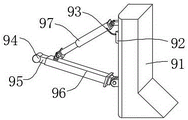
FIG. 2 is a schematic structural view of the middle supporting mechanism of the present invention;
fig. 3 is a schematic cross-sectional view of the middle sleeve of the present invention.
In the figure: 1. a limiting frame; 2. a slider; 3. a fixed block; 4. a wire rope; 5. a fixed block; 6. a baffle plate; 7. a rotating shaft; 8. a through hole; 9. a support mechanism; 10. an electric motor; 11. a fixed seat; 12. a support frame; 13. a chute; 14. a shutter plate; 15. reinforcing ribs; 16. a reinforcing plate; 91. fixing a column; 92. a hydraulic cylinder; 93. an oil pipe; 94. a contact head; 95. a movable rod; 951. a movable block; 96. a sleeve; 961. a spring; 962. a hollow interior cavity; 97. a hydraulic telescopic rod.
Detailed Description
The technical solutions in the embodiments of the present invention will be described clearly and completely with reference to the accompanying drawings in the embodiments of the present invention, and it is obvious that the described embodiments are only some embodiments of the present invention, not all embodiments. Based on the embodiments in the present invention, all other embodiments obtained by a person skilled in the art without creative work belong to the protection scope of the present invention.
Referring to fig. 1-3, the present invention provides a technical solution: the gate for the hydraulic engineering comprises a gate plate 14, a support frame 12 and a motor 10, wherein the top end of the support frame 12 is fixedly connected with a fixed seat 11, the top end of the fixed seat 11 is fixedly connected with the motor 10, an output shaft of the motor 10 is fixedly connected with one end of a rotating shaft 7, the motor 10 can drive the rotating shaft 7 to rotate, the other end of the rotating shaft 7 is rotatably connected with an inserted fixed block 5, the rotating shaft 7 can rotate in the fixed block 5, the fixed block 5 can enhance the rotating stability of the rotating shaft 7, and the bottom end of the fixed block 5 is fixedly connected with the top end of the support frame 12 and can play a role in fixing;
one end of a steel cable 4 is fixedly connected on the periphery of a rotating shaft 7, the steel cable 4 penetrates through the inner side of a through hole 8, the through hole 8 is arranged at the top of a support frame 12 in a penetrating way, the other end of the steel cable 4 is fixedly connected with the top end of a fixing lug 3, the bottom end of the fixing lug 3 is fixedly connected with the top end of a flashboard 14, the steel cable 4 can be wound on the periphery when the rotating shaft 7 rotates, the flashboard 14 is pulled to move up and down, the two sides of the flashboard 14 are fixedly connected with sliders 2, the periphery of each slider 2 is slidably connected with a chute 13, the sliders 2 can slide in the chute 13, the chute 13 is arranged on the inner side of the support frame 12, a reinforcing plate 16 is fixedly connected at the bottom of the rear side of the flashboard 14, the reinforcing plate 16 is favorable for enhancing the pressure resistance of the bottom of the flashboard 14, a limiting frame 1 is arranged, the hydraulic telescopic rod 97 and the sleeve 96 can rotate up and down on one side of the fixed column 14, the other end of the hydraulic telescopic rod 97 is hinged to the upper surface of the sleeve 96 on the side far away from the fixed column 91, and the hydraulic telescopic rod 97 can move the sleeve 96 to rotate along the hinged part of the bottom end of the sleeve 96 and the fixed column 91;
the fixed end of the hydraulic telescopic rod 97 is connected with a hydraulic cylinder 92 through an oil pipe 93, the hydraulic cylinder 92 can control the hydraulic telescopic rod 97 to perform telescopic motion through the oil pipe 93, the hydraulic cylinder 92 is fixedly installed on the front side of the fixed column 91, a hollow inner cavity 962 is formed in the sleeve 96, the bottom wall of the hollow inner cavity 962 is fixedly connected with one end of a spring 961, the spring 961 can move in the hollow inner cavity 962, the other end of the spring 961 is fixedly connected with the inner side of a movable block 951, and the spring 961 can push the movable block 951 to slide, meanwhile, the movable block 951 can compress the spring 961, the periphery of the movable block 951 is in sliding connection with the inner side wall of the hollow inner cavity 962, the movable block 951 can slide inside the hollow inner cavity 952, the outer side of the movable block 951 is fixedly connected with one end of a movable rod 95, the movable block 951 can move along with the movable rod 95, the other end of the movable rod 95 is fixedly connected with a contact head 94, the movable rod 95 can drive the contact head 94 to move, and the contact head 94 abuts against the inner side of the limiting frame 1 on the back of the reinforcing plate 16;
the two groups of steel cables 4 are favorable for enhancing the stability of the traction gate plate 14, two baffles 6 are fixedly arranged on the periphery of the rotating shaft 7 on the two sides of each steel cable 4, and each baffle 6 is disc-shaped, so that the steel cables 4 can be conveniently wound on the periphery of the rotating shaft 7;
the bottom of the gate plate 14 is thicker than the top, and the bottom of the back side is inclined outwards, so that the pressure resistance of the bottom of the gate plate 14 is improved;
the back of the gate plate 14 is provided with a plurality of reinforcing ribs 15, and the reinforcing ribs 15 are parallel to each other and arranged along the vertical direction, so that the structural strength of the gate plate 14 is enhanced, and the pressure resistance is enhanced;
the bottom of the back side of the fixed column 91 is provided with a reinforcing protrusion, so that the fixed column 91 is favorably fixed, and the front side of the fixed column 91 is provided with an arc-shaped chamfer, so that when water flow passes through the fixed column 91, the resistance met by the water flow is reduced;
the contact head 94 is circular in section and is convenient to abut against the reinforcing plate 16 inside the limiting frame 1;
the end of the sleeve 96 in contact with the movable rod 95 is provided with a limit protrusion to prevent the movable rod 95 from sliding out of the sleeve 96.
The working principle is as follows: when the utility model is used, the support frame 12 and the fixing column 91 are firstly fixed at proper positions, the fixing column 91 is arranged at the rear side of the flashboard 14 and can drive the rotating shaft 7 to rotate through the motor 10, the steel cable 4 wound around the periphery can be put down when the rotating shaft 7 rotates, the flashboard 14 is pulled to move downwards, the sliding blocks 2 at two sides of the flashboard 14 can slide in the sliding grooves 13, a certain supporting effect can be provided for two sides of the flashboard 14, and the flashboard 14 can move up and down;
hydraulic cylinder 92 can control hydraulic telescoping rod 97 through oil pipe 93 and carry out concertina movement, hydraulic telescoping rod 97 can transfer sleeve 96 along the way sleeve 96 bottom and the articulated part of fixed column 91 and rotate, control sleeve 96 moves down, make contact 94 support 1 inboard at the spacing frame of gusset plate 16 back, contact 94 promotes movable rod 95 and movable block 951 compression spring 96 simultaneously, can fully make contact 94 support tight gusset plate 16, and provide continuous pressure, and when receiving strong impact, has the cushioning effect, when flashboard 14 is opened to needs, can drive sleeve 96 through hydraulic telescoping rod 92 and upwards rotate, withdraw sleeve 96, just can drive pivot 7 through motor 10 and rotate, can be 4 windings of steel cable in week side when pivot 7 rotates, pull flashboard 14 and upwards move.
Although embodiments of the present invention have been shown and described, it will be appreciated by those skilled in the art that changes, modifications, substitutions and alterations can be made in these embodiments without departing from the principles and spirit of the invention, the scope of which is defined in the appended claims and their equivalents.