CN214209994U - Two-stage desulfurization and purification equipment for boiler flue gas - Google Patents
Two-stage desulfurization and purification equipment for boiler flue gas Download PDFInfo
- Publication number
- CN214209994U CN214209994U CN202023292074.7U CN202023292074U CN214209994U CN 214209994 U CN214209994 U CN 214209994U CN 202023292074 U CN202023292074 U CN 202023292074U CN 214209994 U CN214209994 U CN 214209994U
- Authority
- CN
- China
- Prior art keywords
- flue gas
- water
- subassembly
- fixed mounting
- box
- Prior art date
- Legal status (The legal status is an assumption and is not a legal conclusion. Google has not performed a legal analysis and makes no representation as to the accuracy of the status listed.)
- Active
Links
Images


Abstract
The utility model discloses a boiler flue gas two-stage desulfurization clarification plant, the on-line screen storage device comprises a base, the top fixed mounting of base has the condensation subassembly, one side fixed mounting of condensation subassembly has the subassembly of spraying, fixed mounting has the suction pump between the subassembly of spraying, one side movable mounting of suction pump has the water conservancy diversion subassembly, the fixed air duct that is provided with in top of water conservancy diversion subassembly. The utility model discloses a fixed mounting has the spraying assembly in one side of condensation subassembly, the input that can utilize the suction pump passes through the water piping connection water tank, be equipped with the sulphide absorption liquid in the water tank, the aqueduct is connected to the output of suction pump simultaneously, the suction pump during operation, in the sulphide absorption liquid drum income retaining pipe in the water tank, spray away through the shower nozzle of retaining socle portion at last, sulphide absorption liquid in having solved traditional flue gas can not fully contact with the flue gas, can not realize the abundant absorption of sulphide in the flue gas, lead to the not good problem of purifying effect of flue gas.
Description
Technical Field
The utility model relates to a flue gas desulfurization purifies technical field, specifically is boiler flue gas two-stage desulfurization clarification plant.
Background
Air pollution, also called air pollution, according to the definition of the international organization for standardization, air pollution refers to the phenomenon that certain substances enter the atmosphere due to human activities or natural processes, present sufficient concentration and reach sufficient time, and thus harm the comfort, health and welfare of human beings or the environment, in other words, as long as the quantity, the nature and the time of the existing substance are enough to affect human beings or other organisms and properties, we can call it as air pollutant, with the stricter and stricter environmental requirements, SO2, dust, nitrogen oxides and the like in the flue gas discharged into the environment have strict standard requirements, and therefore the flue gas discharged needs to be purified, and in the purification, the existing two-stage desulfurization and purification equipment for the flue gas of the boiler has many problems or defects:
in practical use, sulfide absorption liquid in the flue gas cannot be in full contact with the flue gas, so that the sulfide in the flue gas cannot be fully absorbed, the flue gas is poor in purification effect, and meanwhile, the purified flue gas still can carry a small amount of sulfide and is directly discharged into the air, so that certain environmental pollution can be caused in the past for a long time.
SUMMERY OF THE UTILITY MODEL
An object of the utility model is to provide a boiler flue gas two-stage desulfurization clarification plant to solve the problem that proposes among the above-mentioned background art.
In order to achieve the above object, the utility model provides a following technical scheme: boiler flue gas two-stage desulfurization clarification plant, the on-line screen storage device comprises a base, the top fixed mounting of base has the condensation subassembly, one side fixed mounting of condensation subassembly has the spraying assembly, fixed mounting has the suction pump between the spraying assembly, one side movable mounting of suction pump has the water conservancy diversion subassembly, the fixed air duct that is provided with in top of water conservancy diversion subassembly, the top fixed mounting of air duct has filtering component, one side fixed mounting of water conservancy diversion subassembly has the motor, one side fixed mounting of motor has the purification subassembly.
Preferably, the spraying assembly comprises a water tank, a water inlet pipe is fixedly arranged at the top of the water tank, a water guide pipe is fixedly arranged at the top of the water inlet pipe, and a water storage pipe is fixedly arranged on one side of the water guide pipe.
Preferably, the purification assembly comprises a water tank, wherein second supporting blocks are fixedly mounted on two sides of the bottom of the water tank, a vent pipe is fixedly arranged at the top of the water tank, and an exhaust hole is fixedly formed in one end of the vent pipe.
Preferably, the filter assembly comprises a filter box, wherein first support blocks are fixedly mounted on two sides of the bottom of the filter box, a first filter screen is fixedly arranged in the filter box, and a second filter screen is fixedly arranged at the bottom of the first filter screen.
Preferably, the condensation subassembly includes the box, and the opposite side of box runs through and is provided with the water inlet, and the fixed intake pipe that is provided with in bottom of water inlet, the fixed delivery port that is provided with in bottom of intake pipe, and one side of box runs through and is provided with the outlet duct, and the inside fixed mounting of box has the cooling cylinder, and the iron mesh is installed to the inside equidistance of cooling cylinder.
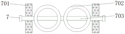
Preferably, the guide assembly comprises a rotating shaft, a guide ring is fixedly mounted on the surface of the rotating shaft, and guide plates are fixedly mounted on two sides of the guide ring.
Compared with the prior art, the beneficial effects of the utility model are that: the two-stage desulfurization and purification equipment for the boiler flue gas has the following advantages:
(1) the spraying assembly is fixedly arranged on one side of the condensing assembly, the input end of the water suction pump can be connected with the water tank through the water inlet pipe, sulfide absorption liquid is filled in the water tank, the output end of the water suction pump is connected with the water guide pipe, and when the water suction pump works, the sulfide absorption liquid in the water tank is blown into the water storage pipe and is sprayed out through the spray head at the bottom of the water storage pipe, so that the problems that the sulfide absorption liquid in the traditional flue gas cannot be fully contacted with the flue gas, the sulfide in the flue gas cannot be fully absorbed, and the flue gas purification effect is poor are solved;
(2) the purification assembly is fixedly arranged on one side of the motor, purified flue gas can be guided into the water tank containing sulfide absorption liquid by using the vent pipe, a plurality of exhaust holes are formed in one end, extending into the water tank, of the vent pipe, the contact area between the flue gas and the sulfide absorption liquid in the water tank is increased, and a supporting effect is provided for the water tank by installing the second supporting block, so that the problem that the traditional purified flue gas still carries a small amount of sulfide and is directly discharged into the air, and certain environmental pollution is caused for a long time in the past is solved;
(3) through the top fixed mounting at the base there is the condensation subassembly, in going into the condensing box with the flue gas through the intake pipe, be provided with a plurality of iron net in the condensing box, slow down the flow velocity of flue gas, be provided with water inlet and delivery port with one side at the box, can be used for the water to retrieve the heat that contains in the flue gas and utilize, can cool down the flue gas simultaneously, the flue gas after cooling down at last passes through the outlet duct and gets into the rose box and carry out filtration processing.
Drawings
Fig. 1 is a schematic structural view of the present invention;
FIG. 2 is a schematic view of a partial structure of the purification assembly of the present invention;
FIG. 3 is a schematic view of a partial structure of the filter assembly of the present invention;
fig. 4 is a schematic view of a partial structure of the diversion assembly of the present invention;
fig. 5 is a schematic view of a partial structure of the condensing assembly of the present invention.
In the figure: 1. a condensing assembly; 101. a water inlet; 102. an air inlet pipe; 103. a water outlet; 104. a condenser tank; 105. an air outlet pipe; 106. an iron net; 107. a box body; 2. a spray assembly; 201. a water conduit; 202. a water inlet pipe; 203. a water tank; 204. a water storage pipe; 3. a water suction pump; 4. a base; 5. a filter assembly; 501. a filter box; 502. a first support block; 503. a first filter screen; 504. a second filter screen; 6. an air duct; 7. a flow guide assembly; 701. a baffle; 702. a flow guide ring; 703. a rotating shaft; 8. a motor; 9. a purification assembly; 901. a breather pipe; 902. an exhaust hole; 903. a water tank; 904. a second support block.
Detailed Description
The technical solutions in the embodiments of the present invention will be described clearly and completely with reference to the accompanying drawings in the embodiments of the present invention, and it is obvious that the described embodiments are only some embodiments of the present invention, not all embodiments. Based on the embodiments in the present invention, all other embodiments obtained by a person skilled in the art without creative work belong to the protection scope of the present invention.
Referring to fig. 1-5, the present invention provides an embodiment: the two-stage desulfurization and purification equipment for the boiler flue gas comprises a base 4, wherein a condensation component 1 is fixedly installed at the top of the base 4, the condensation component 1 comprises a box body 107, a water inlet 101 is formed in the other side of the box body 107 in a penetrating mode, an air inlet pipe 102 is fixedly arranged at the bottom of the water inlet 101, a water outlet 103 is fixedly arranged at the bottom of the air inlet pipe 102, an air outlet pipe 105 is formed in one side of the box body 107 in a penetrating mode, a condensation box 104 is fixedly installed inside the box body 107, and iron nets 106 are installed inside the condensation box 104 at equal intervals;
specifically, as shown in fig. 1 and 5, when in use, the condensation assembly 1 is fixedly installed at the top of the base 4, flue gas is blown into the condensation box 104 through the air inlet pipe 102, the multiple iron nets 106 are arranged in the condensation box 104 to slow down the flow speed of the flue gas, and meanwhile, a water inlet 101 and a water outlet 103 are arranged on one side of the box body 107, so that heat contained in the flue gas can be recycled by a water body, meanwhile, the flue gas can be cooled, the flue gas after being cooled finally enters the filter box 501 through the air outlet pipe 105 for filtering treatment, and the base 4 is installed to provide a supporting effect for the whole device, so that the normal work of the device is ensured;
a spraying component 2 is fixedly installed on one side of the condensing component 1, the spraying component 2 comprises a water tank 203, a water inlet pipe 202 is fixedly arranged on the top of the water tank 203, a water guide pipe 201 is fixedly arranged on the top of the water inlet pipe 202, a water storage pipe 204 is fixedly arranged on one side of the water guide pipe 201, a water suction pump 3 is fixedly installed between the spraying components 2, a flow guide component 7 is movably installed on one side of the water suction pump 3, the flow guide component 7 comprises a rotating shaft 703, a flow guide ring 702 is fixedly installed on the surface of the rotating shaft 703, flow guide plates 701 are fixedly installed on both sides of the flow guide ring 702, an air guide pipe 6 is fixedly arranged on the top of the flow guide component 7, a filtering component 5 is fixedly installed on the top of the air guide pipe 6, the filtering component 5 comprises a filtering box 501, first supporting blocks 502 are fixedly installed on both sides of the bottom of the filtering box 501, a first filtering net 503 is fixedly arranged in the filtering box 501, and a second filtering net 504 is fixedly arranged on the bottom of the first filtering net 503, a motor 8 is fixedly arranged on one side of the flow guide assembly 7;
specifically, as shown in fig. 1, 3 and 4, when in use, the spraying assembly 2 is fixedly installed on one side of the condensing assembly 1, the input end of the water suction pump 3 can be utilized to be connected with the water tank 203 through the water inlet pipe 202, sulfide absorption liquid is filled in the water tank 203, meanwhile, the output end of the water suction pump 3 is connected with the water guide pipe 201, when the water suction pump 3 works, the sulfide absorption liquid in the water tank 203 is blown into the water storage pipe 204 and is finally sprayed out through the spray head at the bottom of the water storage pipe 204, so that the problems that the sulfide absorption liquid in the traditional flue gas cannot be fully contacted with the flue gas, the sulfide in the flue gas cannot be fully absorbed, and the flue gas purification effect is poor are solved, the diversion assembly 7 is movably installed at the bottom of the spraying assembly 2, the output end of the motor 8 can be utilized to drive the rotating shaft 703 to rotate, and thereby the diversion rings 702 and the diversion plates 701 on the surface of the rotating shaft 703 to rotate, the flow direction of the smoke-removing gas can be changed, the flow time of the smoke in the desulfurization chamber is prolonged, the desulfurization effect is better, the spraying assembly 2 and the flow guide assembly 7 are arranged in the desulfurization chamber, the smoke dust and ash are treated before the smoke desulfurization by installing the filtering assembly 5, the filtering effect is improved by the mutual matching of the first filtering net 503 and the second filtering net 504, meanwhile, the door body is arranged on the surface of the filtering box 501, the door handle can be pulled, the door body is opened, the first filtering net 503 and the second filtering net 504 are cleaned regularly, the filtering effect is ensured, the water suction pump 3 is electrically connected with an external power supply through a lead, the model of the water suction pump 3 can be 25WBZ2-8, under the condition that the water suction pump 3 is air in a water pumping pipe, the water pressure lower than the water pumping port under the action of atmospheric pressure by utilizing the negative pressure formed when the water suction pump 3 works, then discharged from the water discharge end of the water suction pump 3, the motor 8 is electrically connected with an external power supply through a lead, the motor 8 can be a Y90L-2 motor, the motor 8 is used for converting electric energy into mechanical energy and mainly comprises an electromagnet winding or a distributed stator winding for generating a magnetic field and a rotating armature or a rotor, and under the action of a rotating magnetic field of the stator winding, current passes through the effective edge of the stator winding and is driven to rotate under the action of the magnetic field;
a purification assembly 9 is fixedly installed on one side of the motor 8, the purification assembly 9 comprises a water tank 903, a second supporting block 904 is fixedly installed on both sides of the bottom of the water tank 903, a vent pipe 901 is fixedly arranged on the top of the water tank 903, and an exhaust hole 902 is fixedly arranged at one end of the vent pipe 901;
specifically, as shown in fig. 1 and 2, during the use, through one side fixed mounting at motor 8 there is purification assembly 9, can utilize in the flue gas leading-in basin 903 that contains the sulphide absorbed liquid after the breather pipe 901 will purify, the one end that stretches into basin 903 at breather pipe 901 is provided with a plurality of exhaust holes 902, increased in flue gas and basin 903 with the area of contact of sulphide absorbed liquid, through installing second supporting shoe 904, for basin 903 provides the supporting role, the flue gas that has solved traditional after being purified still can carry a small amount of sulphide, directly discharge in the air, in the past for a long time, can cause certain environmental pollution's problem.
The working principle is as follows: when the cooling device is used, firstly, the condensing assembly 1 is fixedly installed at the top of the base 4, smoke is blown into the condensing box 104 through the air inlet pipe 102, the plurality of iron nets 106 are arranged in the condensing box 104 to slow down the flow speed of the smoke, meanwhile, the water inlet 101 and the water outlet 103 are arranged on one side of the box body 107, heat contained in the smoke can be recycled by a water body, meanwhile, the smoke can be cooled, and finally, the cooled smoke enters the filter box 501 through the air outlet pipe 105 to be filtered;
secondly, the spraying component 2 is fixedly arranged on one side of the condensing component 1, the input end of the water suction pump 3 can be connected with the water tank 203 through the water inlet pipe 202, sulfide absorption liquid is filled in the water tank 203, meanwhile, the output end of the water suction pump 3 is connected with the water guide pipe 201, and when the water suction pump 3 works, the sulfide absorption liquid in the water tank 203 is blown into the water storage pipe 204 and is sprayed out through a spray head at the bottom of the water storage pipe 204;
finally, through the fixed mounting of the purification subassembly 9 in one side of motor 8, can utilize in the breather pipe 901 guides into the basin 903 that contains the sulphide absorption liquid with the flue gas after purifying, be provided with a plurality of exhaust holes 902 in the one end that breather pipe 901 stretches into basin 903, increased the area of contact of flue gas and basin 903 in with the sulphide absorption liquid, through installing second supporting shoe 904, provide supporting role for basin 903.
It is obvious to a person skilled in the art that the invention is not restricted to details of the above-described exemplary embodiments, but that it can be implemented in other specific forms without departing from the spirit or essential characteristics of the invention. The present embodiments are therefore to be considered in all respects as illustrative and not restrictive, the scope of the invention being indicated by the appended claims rather than by the foregoing description, and all changes which come within the meaning and range of equivalency of the claims are therefore intended to be embraced therein, and any reference signs in the claims are not intended to be construed as limiting the claim concerned.
Claims (6)
1. Boiler flue gas two-stage desulfurization clarification plant, including base (4), its characterized in that: the utility model discloses a solar water heater, including base (4), the top fixed mounting of base (4) has condensation subassembly (1), one side fixed mounting of condensation subassembly (1) has spraying subassembly (2), fixed mounting has water suction pump (3) between spraying subassembly (2), one side movable mounting of water suction pump (3) has water conservancy diversion subassembly (7), the fixed air duct (6) that is provided with in top of water conservancy diversion subassembly (7), the top fixed mounting of air duct (6) has filtering component (5), one side fixed mounting of water conservancy diversion subassembly (7) has motor (8), one side fixed mounting of motor (8) has purification subassembly (9).
2. The two-stage desulfurization purification apparatus for boiler flue gas according to claim 1, characterized in that: the spraying assembly (2) comprises a water tank (203), a water inlet pipe (202) is fixedly arranged at the top of the water tank (203), a water guide pipe (201) is fixedly arranged at the top of the water inlet pipe (202), and a water storage pipe (204) is fixedly arranged on one side of the water guide pipe (201).
3. The two-stage desulfurization purification apparatus for boiler flue gas according to claim 1, characterized in that: the purification assembly (9) comprises a water tank (903), wherein second supporting blocks (904) are fixedly mounted on two sides of the bottom of the water tank (903), a vent pipe (901) is fixedly arranged on the top of the water tank (903), and an exhaust hole (902) is fixedly arranged at one end of the vent pipe (901).
4. The two-stage desulfurization purification apparatus for boiler flue gas according to claim 1, characterized in that: the filter assembly (5) comprises a filter box (501), wherein first supporting blocks (502) are fixedly mounted on two sides of the bottom of the filter box (501), a first filter screen (503) is fixedly arranged inside the filter box (501), and a second filter screen (504) is fixedly arranged at the bottom of the first filter screen (503).
5. The two-stage desulfurization purification apparatus for boiler flue gas according to claim 1, characterized in that: condensation subassembly (1) includes box (107), and the opposite side of box (107) runs through and is provided with water inlet (101), and the fixed intake pipe (102) that is provided with in bottom of water inlet (101), and the fixed delivery port (103) that is provided with in bottom of intake pipe (102), one side of box (107) runs through and is provided with outlet duct (105), and the inside fixed mounting of box (107) has condensing box (104), and iron net (106) are installed to the inside equidistance of condensing box (104).
6. The two-stage desulfurization purification apparatus for boiler flue gas according to claim 1, characterized in that: the flow guide assembly (7) comprises a rotating shaft (703), a flow guide ring (702) is fixedly mounted on the surface of the rotating shaft (703), and flow guide plates (701) are fixedly mounted on two sides of the flow guide ring (702).
Priority Applications (1)
| Application Number | Priority Date | Filing Date | Title |
|---|---|---|---|
| CN202023292074.7U CN214209994U (en) | 2020-12-30 | 2020-12-30 | Two-stage desulfurization and purification equipment for boiler flue gas |
Applications Claiming Priority (1)
| Application Number | Priority Date | Filing Date | Title |
|---|---|---|---|
| CN202023292074.7U CN214209994U (en) | 2020-12-30 | 2020-12-30 | Two-stage desulfurization and purification equipment for boiler flue gas |
Publications (1)
| Publication Number | Publication Date |
|---|---|
| CN214209994U true CN214209994U (en) | 2021-09-17 |
Family
ID=77707357
Family Applications (1)
| Application Number | Title | Priority Date | Filing Date |
|---|---|---|---|
| CN202023292074.7U Active CN214209994U (en) | 2020-12-30 | 2020-12-30 | Two-stage desulfurization and purification equipment for boiler flue gas |
Country Status (1)
| Country | Link |
|---|---|
| CN (1) | CN214209994U (en) |
-
2020
- 2020-12-30 CN CN202023292074.7U patent/CN214209994U/en active Active
Similar Documents
| Publication | Publication Date | Title |
|---|---|---|
| CN112774348B (en) | Industrial waste gas purifies uses high-efficiency processing device | |
| CN213334477U (en) | More efficient desulfurization dust remover | |
| CN214209994U (en) | Two-stage desulfurization and purification equipment for boiler flue gas | |
| CN211328694U (en) | A atmosphere processing apparatus for environment is administered | |
| CN213853872U (en) | Safe and environment-friendly efficient dust removal spraying desulfurization equipment | |
| CN209791266U (en) | Washing device for denitration and desulfurization of flue gas | |
| CN111821799B (en) | Efficient wet dust removal equipment for air purification | |
| CN209490626U (en) | The preposition dedusting paint-removing combination unit of heat accumulating type catalytic combustion | |
| CN210473507U (en) | Energy-saving environment-friendly acid-base waste gas treatment comprehensive washing tower | |
| CN209848585U (en) | Environment-friendly chemical industry equipment exhaust treatment device | |
| CN210602043U (en) | Multi-bubble rotary cleaning air purifier | |
| CN213885535U (en) | Collection device for exhaust-gas treatment | |
| CN111219765A (en) | Oil smoke processing apparatus and machine of cooking thereof | |
| CN112957894A (en) | High-efficient integration landfill leachate sewage station exhaust treatment device | |
| CN203043778U (en) | Dust and exhaust gas treatment system in workshop | |
| CN214287388U (en) | Remove formaldehyde dust collector in polyformaldehyde production process | |
| CN219399527U (en) | Rotational flow washing tower for waste gas treatment | |
| CN217773736U (en) | Sun-proof anti-weathering PP spray tower | |
| CN212999051U (en) | Waste gas purification system with water circulation mechanism | |
| CN220939787U (en) | Atmospheric pollution treatment dust collector | |
| CN211537006U (en) | Wet dust remover | |
| CN212068223U (en) | Boiler tail gas discharging equipment | |
| CN213221457U (en) | Industrial waste gas treatment device with good dust removal effect | |
| CN219829587U (en) | Absorption tower for power plant | |
| CN212141806U (en) | Dust collector for smelting management |
Legal Events
| Date | Code | Title | Description |
|---|---|---|---|
| GR01 | Patent grant | ||
| GR01 | Patent grant |